JVC PD-42D30ES User manual

1
PD-42/35D30ES/ LCT1375-001A-U / All cover
PDP FARBFERNSEHGERÄT BEDIENUNGSANLEITUNG
PDP TELEVISEUR COULEUR MANUEL D’INSTRUCTIONS
PDP KLEURENTELEVISIE GEBRUIKSAANWIJZING
PDP TELEVISOR A COLOR MANUAL DE INSTRUCCIONES
PDP TELEVISORE A COLORI ISTRUZIONI
PDP TELEVISOR A CORES INSTRUÇÕES
PDP COLOUR TELEVISION INSTRUCTIONS
ENGLISH
DEUTSCH
FRANÇAIS
NEDERLANDS
CASTELLANO
ITALIANO
PORTUGUÊS
Cover 1
PD-42D30ES
PD-35D30ES
LCT1375-001A-U_Cover.fm Page 1 Thursday, January 30, 2003 11:10 AM

PD-42/35D30ES / LCT1375-001A-U / English (EK)
Cover 2
PD-42/35D30ES / LCT1375-001A-U / English (EK)
Warning
DO NOT cut off the mains plug from this equipment. If
the plug fitted is not suitable for the power points in your
home or the cable is too short to reach a power point, then
obtain an appropriate safety approved extension lead or
adaptor or consult your dealer.
If nonetheless the mains plug is cut off, remove the fuse and
dispose of the plug immediately, to avoid a possible shock
hazard by inadvertent connection to the mains supply.
If a new mains plug has to be fitted, then follow the
instruction given below:
Important
Do not make any connection to the larger terminal which is
marked with the letter E or by the safety earth symbol or
coloured green or green-and-yellow.
The wires in the mains lead on this product are coloured in
accordance with the following code:
Blue: Neutral
Brown: Live
As these colours may not correspond with the coloured
marking identifying the terminals in your plug proceed as
follows:
The wire which is coloured blue must be connected to the
terminal which is marked with the letter N or coloured
black.
The wire which is coloured brown must be connected to the
terminal which is marked with the letter L or coloured red.
When replacing the fuse, use only a correctly rated
approved type and always re-fit the fuse cover.
If in doubt — consult a competent electrician.
How to replace the fuse
Open the fuse compartment with a
blade screwdriver, and replace the
fuse.
Guidelines for safe operation
This equipment has been designed and manufactured to comply with international safety standards. However, as with any electrical
appliance, care must be taken to ensure optimal results and operational safety.
• Before attempting to use this equipment, read the operating instructions thoroughly.
• Ensure that all electrical connections (including the mains plug, extension leads, etc.) have been made in accordance with the
manufacturer’s instructions.
• If ever in doubt about the installation, operation or safety of this equipment, consult your dealer.
• Handle all glass panels or covers with care.
• Never operate this equipment if it appears damaged or operates abnormally. Turn the power off, disconnect the main power plug
and consult your dealer.
• Never remove any affixed panels or covers. Doing so may result in electrical shock.
• Never leave this equipment operating unattended unless otherwise specifically stated that it is designed to do so or in standby
mode. Only use the designated power switch to turn off the power and ensure that all potential users are instructed how to do so.
Make special arrangements for infirm or handicapped persons.
• Never watch TV while operating a motor vehicle. It is illegal to watch TV while driving.
• Never listen to headphones at high volume. Doing so may damage your hearing.
• Never obstruct the ventilation of this equipment. Doing so may cause overheating and result in a malfunction or damage.
• Never use makeshift stands or attempt to affix legs with wood screws. When using a manufacturer’s approved stand or legs, use
only the fixtures provided and follow the installation instructions.
• Never allow this equipment to be exposed to rain or moisture.
• Never allow anyone, especially children, to insert anything into an opening in the case. Doing so may result in a fatal electrical
shock.
• Never guess or take chances with electrical equipment of any kind. It is better to be safe than sorry.
Fuse
PD-42&35D30ES(EK)_Eng.book Page 0 Thursday, January 30, 2003 10:21 AM

1
PD-42/35D30ES / LCT1375-001A-U / English (EK)
ENGLISH
Thank you for buying this JVC colour television.
To make sure you understand how to use your new TV, please read this manual thoroughly before you begin.
WARNING
Always use the power cords which are supplied with the TV and receiver.
Some power cords are supplied with this TV. Use the power cord which best suits the area in which you live, and insert it into a correctly
earthed outlet.
Failure to use the supplied power cord or to insert it into a correctly earthed outlet may result in electric shocks.
WARNING
To ensure safety in an emergency such as an earthquake, and to prevent accidents, ensure that measures are taken to prevent the TV
dropping or falling over.
• Use the supplied screws to firmly attach the supplied hooks to the back of the TV, and use commercially available cord to fix the TV
to rigid components such as walls and columns.
WARNING: TO PREVENT FIRE OR SHOCK HAZARD, DO NOT EXPOSE THIS APPLIANCE TO RAIN OR
MOISTURE.
CAUTION:
• Operate only from the power source specified (AC 110 – 240 V,
50/60 Hz) on the unit.
• Avoid damaging the AC plug and power cord.
• When you are not using this unit for a long period of time, it is
recommended that you disconnect the power cord from the
main outlet.
• The ambient temperature for using this unit is 0° to 40°C (32°
to 104°F). Using the unit outside of this range may lead to it not
working correctly or being broken.
MENU
OK
PTV/AV
Supplied hooks
PD-42&35D30ES(EK)_Eng.book Page 1 Thursday, February 13, 2003 11:34 AM

2
PD-42/35D30ES / LCT1375-001A-U / English (EK)
Burn-in
A characteristic of Plasma Display Panels (PDPs) is that displaying the same image for a long time causes a part of the image to stay
on the screen (this is called phosphor burn-in).
Avoid burn-in as follows.
Do not display static images or characters for long periods of time.
• Reduce CONTRAST and BRIGHT on the PICTURE SETTING menu (page 25) when viewing.
Do not view for long periods of time in the REGULAR mode (page 19).
Screen size is normally chosen to ensure that the picture is displayed on the entire screen. After viewing in the REGULAR mode in
which black bands may occur at the left and right of the screen, it is recommended to change to the PANORAMIC mode to display
the picture on the entire screen.
Do not view for long periods of time using the PIP function (page 20) or MULTI-PICTURE function (page 21).
If Burn-in has occurred
If burn-in occurs, try the SNOW NOISE function (page 34). If burn-in is minimal it may gradually become less noticeable.
Note:Once burn-in occurs it will never disappear completely.
19:03 19:03
Burn-in example
While an image is displayed With power OFF
Burn-in example
While an image is displayed With power OFF
PD-42&35D30ES(EK)_Eng.book Page 2 Thursday, February 13, 2003 11:34 AM

3
PD-42/35D30ES / LCT1375-001A-U / English (EK)
ENGLISH
Avoid improper installation and never put the unit where good ventilation is not possible.
When installing this TV, distance recommendations must be maintained between the set and the wall, as well as inside a tightly enclosed
area or piece of furniture.
Adhere to the minimum distance guidelines shown for safe operation.
Failure to heed the following precautions may result in
damage to the TV or remote control.
DO NOT block the TV’s ventilation openings or holes.
(If the ventilation openings or holes are blocked by a newspaper or
cloth, etc., the heat may not be able to get out.)
DO NOT place anything on top of the TV.
(such as cosmetics or medicines, flower vases, potted plants, cups, etc.)
DO NOT allow objects or liquid into the cabinet openings.
(If water or liquid is allowed to enter this equipment, fire or electric
shock may be caused.)
DO NOT place any naked flame sources, such as lighted candles, on
the TV.
D.I.S.T. demonstration
To start the D.I.S.T. demonstration:
Press the abutton to display the MENU (main menu). Then press the yellow button.
A picture split in two (D.I.S.T. turned on and D.I.S.T. turned off) will appear on the screen.
To quit the D.I.S.T. demonstration:
Press the yellow button, bbutton, Ppbuttons or any of the number buttons.
Point defects
PDPs use collections of fine pixels to display images. While there is no problem with more than 99.99% of these pixels, please
understand that a very small number of pixels may not light or may light all the time.
Do not install the TV near electronic equipment that is affected by electromagnetic waves
It may cause interference in images, sound, etc. In particular, keep video equipment away from this product.
Effect on infrared devices
There may be interference while using infrared devices such as infrared cordless headphones.
The surface of the TV screen is easily damaged. Be very careful with it when handling the TV.
Should the TV screen become soiled, wipe it with a soft dry cloth. Never rub it forcefully.
Never use any cleaner or detergent on it.
In the event of a fault, unplug the unit and call a service technician. Do not attempt to repair it yourself or remove the rear cover.
200 mm
100 mm
100 mm
100 mm
100 mm
100 mm
200 mm
50 mm
150 mm
150 mm
PD-42&35D30ES(EK)_Eng.book Page 3 Thursday, February 13, 2003 11:34 AM

4
PD-42/35D30ES / LCT1375-001A-U / English (EK)
CONTENTS
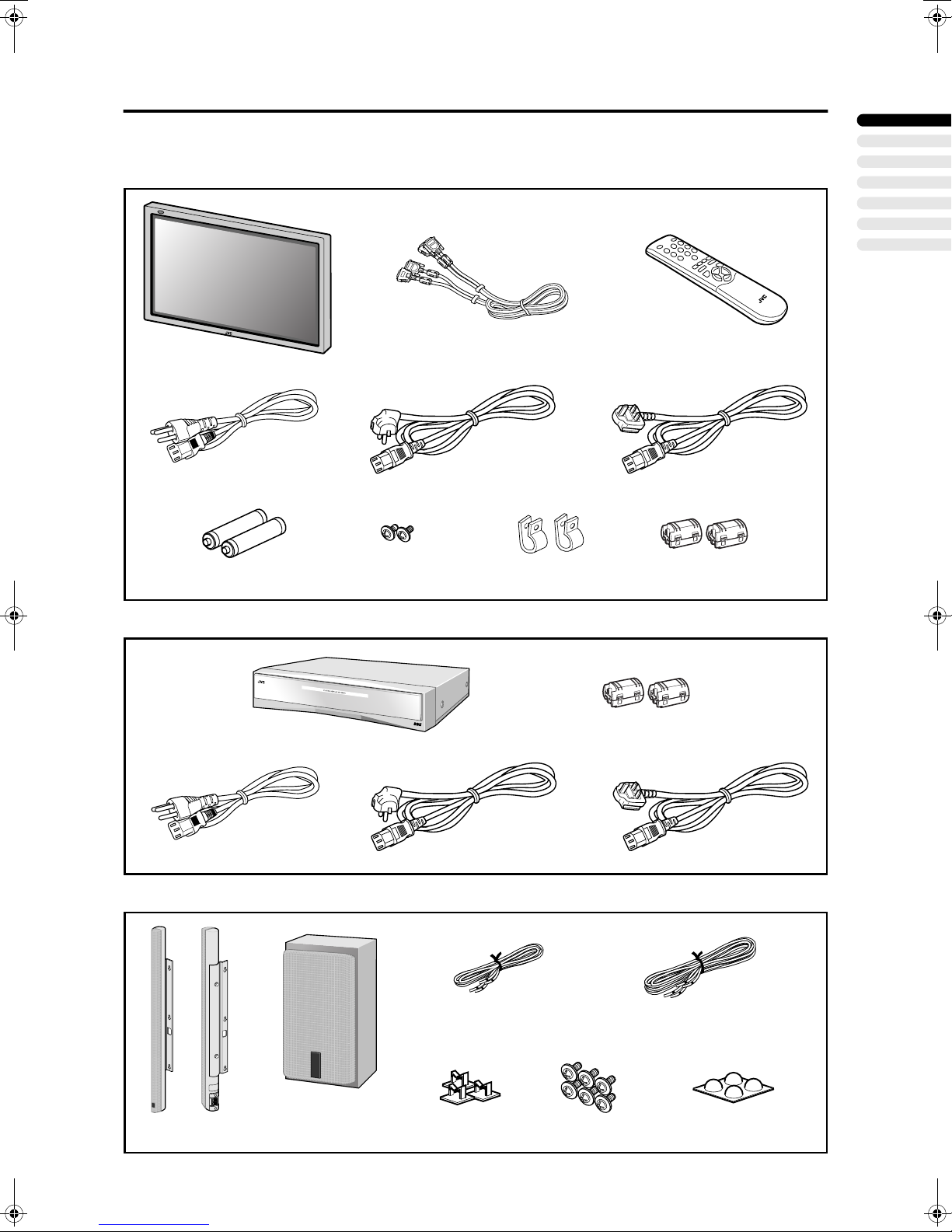
Checking contents of packages............5
Setting up your TV..................................6
Mounting the front speakers, and preparing the
subwoofer .......................................................6
Installation..........................................................7
Putting the batteries into the remote control ......7
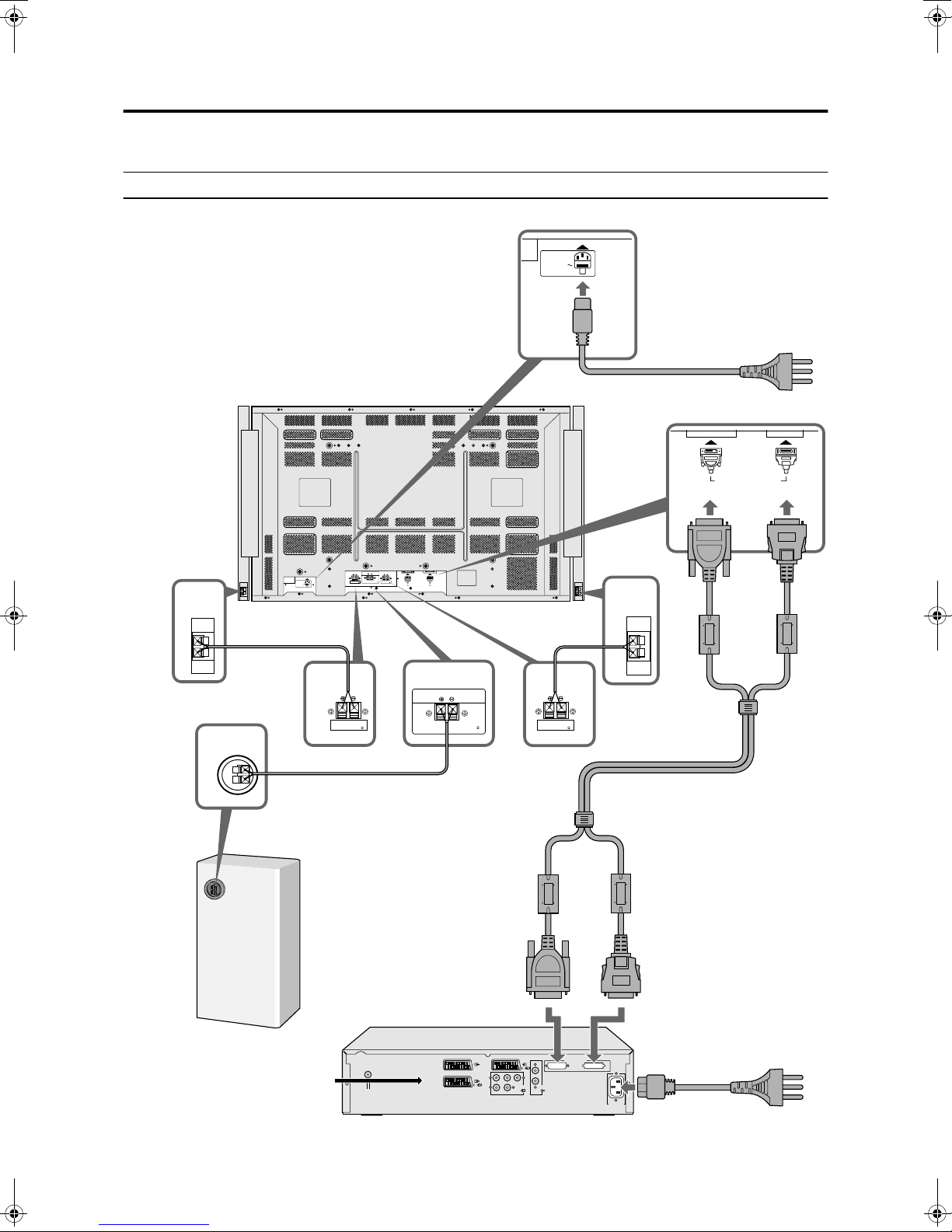
Connections............................................8
Connection diagram...........................................8
Connecting the front speakers and subwoofer
....10
Connecting the TV and receiver ......................11
Connecting the aerial and video cassette
recorder (VCR)..............................................12
Connecting the power cord to the AC outlet ....13
Initial settings .......................................14
T-V LINK functions...........................................15
TV buttons and functions ....................16
Turn the TV on from standby mode .................16
Choose a TV channel ......................................16
Watch images from external devices ...............16
Adjust the volume ............................................16
Using headphones ...........................................16
Using the Menu................................................16
Remote control buttons and
functions............................................17
Turn the TV on or off from standby mode ........17
Choose a TV channel ......................................17
Adjust the volume ............................................18
Watch images from external equipment ..........18
ZOOM function.................................................19
3D SOUND function.........................................19
Displaying the current time ..............................20
Return to TV channel instantly.........................20
Using the FREEZE function .............................20
Using the PIP function .....................................20
Using the MULTI-PICTURE function ...............21
Operating a JVC brand VCR or DVD player ....21
Teletext function...................................22
Basic operation ................................................22
Using the List Mode .........................................22
Hold..................................................................22
Sub-page .........................................................23
Reveal..............................................................23
Size ..................................................................23
Index ................................................................23
Cancel..............................................................23
Using the TV’s menu............................24
Basic operation ................................................24
PICTURE SETTING ...............................25
PICTURE MODE .............................................25
Picture Adjustment...........................................25
COLOUR TEMP...............................................25
PICTURE FEATURES........................... 26
DIGITAL VNR.................................................. 26
Super DigiPure................................................ 26
COLOUR SYSTEM ......................................... 27
MOVIE THEATRE........................................... 27
4:3 AUTO ASPECT......................................... 27
COLOUR MANAGEMENT .............................. 27
PIP (picture-in-picture) .................................... 28
SOUND SETTING ................................. 29
STEREO / I • II ................................................ 29
Sound Adjustment........................................... 29
SPEAKER ....................................................... 29
BBE ................................................................. 29
3D SOUND...................................................... 29
SUBWOOFER................................................. 29
HEADPHONE ................................................. 30
EXT SETTING ....................................... 31
S-IN (S-VIDEO input) ...................................... 31
LIST................................................................. 31
DUBBING........................................................ 31
FEATURES............................................ 33
SLEEP TIMER ................................................ 33
BLUE BACK .................................................... 33
CHILD LOCK................................................... 33
DECODER (EXT-2)......................................... 34
SNOW NOISE................................................. 34
INSTALL................................................ 35
LANGUAGE .................................................... 35
AUTO PROGRAM........................................... 35
EDIT/MANUAL ................................................ 36
Additional menu operations ............... 39
Using the ACI function .................................... 39
Downloading data to a VCR............................ 39
Changing the COUNTRY setting .................... 40
Using the DECODER (EXT-2) function........... 40
Additional preparation......................... 41
Connecting external equipment ...................... 41
CH/CC numbers ................................... 43
Troubleshooting................................... 44
Specifications....................................... 46
PD-42&35D30ES(EK)_Eng.book Page 4 Thursday, February 13, 2003 11:34 AM

5
PD-42/35D30ES / LCT1375-001A-U / English (EK)
ENGLISH
Checking contents of packages
The TV and components are supplied in three packages.
Check that all components are present. Contact your retailer immediately if any components are missing.
TV
Receiver
Speakers
TV
System cable
Hook ×2
Remote control
Power cord
Mounting screw ×2AAA/R03-size batteries
(used to check operation)
Ferrite core ×2
Receiver
Power cord
Ferrite core ×2
Left and right front speakers
(DD speakers)
Speaker cord (for front speakers) ×2
Subwoofer
Speaker cord (for subwoofer) ×1
Cord clamp ×3 Rubber foot for subwoofer ×4
Mounting screw ×6
(only for PD-35D30ES)
PD-42&35D30ES(EK)_Eng.book Page 5 Thursday, February 13, 2003 11:34 AM

6
PD-42/35D30ES / LCT1375-001A-U / English (EK)
Setting up your TV
• Use the stand designed for this TV. For details of how to attach the stand, refer to the stand user’s manual.
• Ensure that the TV is installed on the wall by a skilled installer.
Mounting the front speakers, and preparing the subwoofer
Mounting the front speakers
Mount the supplied DD speakers on the left and right of the TV.
• When using the stand designed for the TV, mount the TV on the stand beforehand.
• Place a soft cloth on the floor for protection before laying the TV down to attach the front speakers.
<PD-42D30ES>
<PD-35D30ES>
• Attach only the supplied DD speakers to the TV.
1 Loosen the speaker mounting
screws at the back of the TV
Using a Philips screwdriver, loosen
the speaker mounting screws (three
each side) until the heads project
approximately 3 mm.
2 Attach the front speakers to
the back of the TV
Place the heads of the screws in the
screw holes in the front speaker
mounting fixture, and slide the
speaker downwards.
3 Lock the front speakers in
place
Tighten the screws to lock the
mounting fixture in place using a
Philips screwdriver.
1 Attach the speaker mounting
screws to the back of the TV
Using a Philips screwdriver, tighten
the speaker mounting screws (three
each side) until approximately
3 mm is left protruding.
2 Attach the front speakers to
the back of the TV
Place the heads of the screws in the
screw holes in the front speaker
mounting fixture, and slide the
speaker downwards.
3 Lock the front speakers in
place
Tighten the screws to lock the
mounting fixture in place using a
Philips screwdriver.
DISPLA
YINPUT
CONNECTTO SYSTEMCABLE
DISPLA
YINPUT
CONNECTTOSYSTEMCABLE
DISPLAY INPUT
CONNECTTOSYSTEMCABLE
PD-42&35D30ES(EK)_Eng.book Page 6 Thursday, February 13, 2003 11:34 AM

7
Setting up your TV
ENGLISH
PD-42/35D30ES / LCT1375-001A-U / English (EK)
Preparing the subwoofer
Either stand the subwoofer vertically or lay it down on its side, peel the
paper from the supplied rubber feet, and stick the feet in the four corners on
the surface to be used as the base. The rubber feet prevent slipping and
resonance, and also protect the speaker cord.
• The subwoofer is not designed to withstand electromagnetic fields. Also, it vibrates and should therefore not be installed near
equipment such as VCR, or equipment where it will be subject to vibration or electromagnetic fields.
Installation
Cautions for installation
• Do not tilt the TV towards the left or right, or towards the back.
• Install the TV in a corner on a wall or on the floor so as to keep cords out of the way.
• Grip the TV (not the front speakers) when moving or installing it after mounting the front speakers to the TV.
• The TV will generate a slight amount of heat during operation. Ensure that sufficient space is available around the TV to allow
satisfactory cooling.
Putting the batteries into the remote control
Use two AAA/R03 dry cell batteries.
Insert the batteries from the -end, making sure the +and -polarities are correct.
• Follow the warnings printed on the batteries.
• Battery life is about six months to one year, depending on how much you use the remote control.
• The batteries we supply are only for setting up and testing your TV, please replace them as soon as you need to.
• If the remote control does not work properly, replace the batteries.
Above the TV: 200 mm or more
Left and right of the TV: 150 mm or more
Behind the TV: 50 mm or more
Above, behind, left and right of the receiver: 100 mm or more
Subwoofer
Mounting example:
Subwoofer to be used
lying down
Rubber feet
Installation example:
MENU
OK
PTV/AV
PD-42&35D30ES(EK)_Eng.book Page 7 Thursday, February 13, 2003 11:34 AM

8
PD-42/35D30ES / LCT1375-001A-U / English (EK)
Connections
Caution
• Turn off all the equipment including the TV before connecting anything.
Connection diagram
<PD-42D30ES>
DISPLAY OUT
AUDIO OUT
R
L
Pr
RL
Pb Y
EXT-3
S
EXT-1
EXT-2
S EXT-4
AC110
-
240V
MAX OUT : 15W IMPEDANCE : 4
SUBWOOFER OUT
FRONT
SPEAKER OUT
MAX OUT : 10W
IMPEDANCE : 6
L
FRONT
SPEAKER OUT
MAX OUT : 10W
IMPEDANCE : 6
R
AC INPUT
110-240V
DISPLAY INPUT
CONNECT TO SYSTEM CABLE
AC INPUT
110-240V
MAXOUT : 15W IMPEDANCE: 4
SUBWOOFEROUT
FRONT
SPEAKEROUT
MAXOUT : 10W
IMPEDANCE: 6
R
FRONT
SPEAKEROUT
MAXOUT : 10W
IMPEDANCE: 6
L
DISPLAYINPUT
CONNECTTO SYSTEM CABLE
Connecting antenna and other equipment
• Refer to page 12 for connection details.
Right front
speaker
TV (back)
Left front
speaker
Cable supplied with TV
• Refer to page 13 for connection
details.
Cable supplied with receiver
• Refer to page 13 for connection details.
Supplied speaker cord
Subwoofer
(back)
Supplied speaker cord Supplied system cable
Receiver (back)
PD-42&35D30ES(EK)_Eng.book Page 8 Thursday, February 13, 2003 11:34 AM

9
Connections
ENGLISH
PD-42/35D30ES / LCT1375-001A-U / English (EK)
<PD-35D30ES>
DISPLAY OUT
AUDIO OUT
R
L
Pr
RL
Pb Y
EXT-3
S
EXT-1
EXT-2
S EXT-4
AC110
-
240V
FRONT
SPEAKER OUT
MAX OUT : 10W
IMPEDANCE : 6
L
FRONT
SPEAKER OUT
MAX OUT : 10W
IMPEDANCE : 6
R
AC INPUT
110-240V
SUBWOOFER
OUT
MAX OUT
:15W
IMPEDANCE
:4
DISPLAY INPUT
CONNECT TO SYSTEM CABLE
AC INPUT
110-240V
SUBWOOFER
OUT
MAXOUT
:15W
IMPEDANCE
:4
DISPLAYINPUT
CONNECTTO SYSTEM CABLE
FRONT
SPEAKEROUT
MAXOUT : 10W
IMPEDANCE: 6
R
FRONT
SPEAKEROUT
MAXOUT : 10W
IMPEDANCE: 6
L
Connecting antenna and other equipment
• Refer to page 12 for connection details.
Right front
speaker
TV (back)
Left front
speaker
Cable supplied with TV
• Refer to page 13 for connection
details.
Cable supplied with receiver
• Refer to page 13 for connection
details.
Supplied speaker cord
Subwoofer
(back)
Supplied speaker cord
Supplied system cable
Receiver (back)
PD-42&35D30ES(EK)_Eng.book Page 9 Thursday, February 13, 2003 11:34 AM

Connections
10
PD-42/35D30ES / LCT1375-001A-U / English (EK)
Connecting the front speakers and subwoofer
Use the supplied speaker cords to connect the speakers to the speaker terminals at the back of the TV.
Connecting the speaker cord to the front speaker terminal
Connect using the supplied front speaker cords.
1 Press the spring-loaded speaker input terminal
lever in the direction of the arrow
2 Press the core of the cord into the terminal and
lock it in place by releasing the lever
• Connect the cord with the black stripe to the -terminal.
The stereo sensation and sound quality will be impaired if the polarity (+, -) of the speaker cords is reversed.
Connecting the speaker cord to the subwoofer terminal
Connect using the supplied subwoofer speaker cord.
1 Press the spring-loaded subwoofer speaker
input terminal lever in the direction of the arrow
2 Press the core of the cord into the terminal and
lock it in place by releasing the lever
• Connect the cord with the black stripe to the -terminal.
The stereo sensation and sound quality will be impaired if the polarity (+, -) of the speaker cords is reversed.
Connecting the speaker cord to the speaker terminal at the back of the TV
Connect the speaker cord from the right of the TV (when viewed from the front) to the speaker terminal R at the back of the TV.
Connect the speaker cord from the left of the TV (when viewed from the front) to the speaker terminal L at the back of the TV.
Connect the speaker cord from the subwoofer to the subwoofer terminal at the back of the TV.
• Connect the cord with the black stripe to the -terminal.
The stereo sensation and sound quality will be impaired if the polarity (+, -) of the speaker cords is reversed.
• The front speakers (DD speakers) and the subwoofer are for use only with this TV, and may be damaged if they are connected to
another amplifier.
1 Press the speaker terminal
lever on the TV in the direction
of the arrow
2 Press the core of the cord into
the terminal
3 Push the terminal lever
upwards
MAX OUT : 10W
IMPEDANCE : 6
FRONT
SPEAKER OUT
R
MAX OUT : 10W
IMPEDANCE : 6
FRONT
SPEAKER OUT
R
MAX OUT : 10W
IMPEDANCE : 6
FRONT
SPEAKER OUT
R
PD-42&35D30ES(EK)_Eng.book Page 10 Thursday, February 13, 2003 11:34 AM

11
Connections
ENGLISH
PD-42/35D30ES / LCT1375-001A-U / English (EK)
Bundling speaker cords
Use the supplied cord clamps to bundle the connected speaker cords together.
• Peel the paper from the back of the cord clamp and attach it at the desired location. To ensure that the cord clamp is firmly
attached, wait a few minutes before inserting the speaker cords into the clamp.
• Ensure that the cord clamp is not attached above a ventilation hole at the back of the TV.
Connecting the TV and receiver
Use the supplied system cable to connect the TV to the receiver.
The two connectors are of different shapes.
Ensure that the pins on connector 1are oriented correctly, press the connector into the socket, and tighten the screws at left and
right to lock it in place.
Press connector 2firmly into place until it is locked.
Disconnecting the system cable
Release connector 1by unscrewing the screws at left and right and removing it from the socket.
Release connector 2by removing it from the socket while pressing the release bottoms on either side.
Cord clamp
Speaker cords
2
1
<PD-42D30ES> <PD-35D30ES>
2
1
<PD-42D30ES> <PD-35D30ES>
PD-42&35D30ES(EK)_Eng.book Page 11 Thursday, January 30, 2003 10:21 AM

Connections
12
PD-42/35D30ES / LCT1375-001A-U / English (EK)
Connecting the aerial and video
cassette recorder (VCR)
• The connecting cables are not provided.
• For further details, refer to the manuals provided with
the devices to be connected.
If you are connecting a VCR, follow A
AA
A→
→→
→B
BB
B→
→→
→
C
CC
Cin the diagram opposite.
If you are not connecting a VCR, follow 1
11
1.
To use the T-V LINK functions, you must have a T-V
LINK compatible VCR connected by a SCART cable Cto
the EXT-2 terminal on the TV. For details about T-V LINK
functions, see “T-V LINK functions” on page 15.
• You can watch a video using the VCR without doing C.
For details, see your VCR instruction manual.
• To connect more equipment, please see “Connecting
external equipment” on page 41.
• To connect additional audio equipment, see “Connecting
Speakers/Amplifier” on page 42.
• If you connect a decoder to a T-V LINK compatible
VCR, set the DECODER (EXT-2) function to ON. For
details, see “Using the DECODER (EXT-2) function”
on page 40.
Otherwise, you will not be able to watch scrambled
channels.
Pr
RL
Pb Y
EXT-
3
S
EXT-1
EXT-2
S EXT-4
75-ohm
Coaxial
Cable
21-pin
SCART
Cable
Back of the receiver
75-ohm Coaxial Cable
AV IN/OUT
Terminal
To Aerial
Output
To Aerial
Input
VCR
Aerial
PD-42&35D30ES(EK)_Eng.book Page 12 Thursday, January 30, 2003 10:21 AM

13
Connections
ENGLISH
PD-42/35D30ES / LCT1375-001A-U / English (EK)
Connecting the power cord to the AC
outlet
Insert the AC plugs on the power cords from the TV and
receiver into AC outlets.
Caution
• Operate only from the power source specified (AC 110
– 240 V, 50/60 Hz) on the unit.
• Failure to use the supplied power cord or to insert it
into a correctly earthed outlet may result in electric
shocks.
Use the supplied power cord which best suits the area in
which you live.
Attaching the ferrite cores
Attach ferrite cores to the power cord.
Using the power cord without ferrite cores may lead to
noise (interference).
Open the ferrite core, insert the power cord and close the
ferrite core.
Attach a ferrite core to each end of the power cord.
Insert the AC plug into a correctly earthed outlet.
The receiver power lamp lights red, and the receiver is in
the standby mode, when the AC plug on the power cord is
connected to an AC outlet.
• Remove the AC plug from the outlet to completely
disconnect the TV from the power supply.
Receiver rear
1Aerial socket (page 12)
2EXT-1 terminal (pages 12, 31, 41)
3EXT-2 terminal (pages 12, 15, 31, 41)
4EXT-3 terminal (pages 31, 41)
5EXT-4 terminal (pages 31, 41)
6AUDIO OUT terminal (page 42)
7DISPLAY OUT terminal (page 11)
8AC INLET (page 13)
AC110
-
240V
Power cord
Back of the receiver
Back of the TV
Power cord
AC INLET
AC INLET
Ferrite core
Supplied ferrite cores
Power cord
Supplied ferrite cores
DISPLAY OUT
AUDIO OUT
R
L
Pr
RL
Pb Y
EXT-3
S
EXT-1
EXT-2
S EXT-4
AC110
-
240V
PD-42&35D30ES(EK)_Eng.book Page 13 Thursday, January 30, 2003 10:21 AM

14
PD-42/35D30ES / LCT1375-001A-U / English (EK)
Initial settings
When the TV is first turned on, it goes into the initial setting
mode, and you will see the JVC logo. Follow the
instructions on the screen display to make the initial
settings.
1 Press the #
##
#button on the remote control
The receiver power lamp changes from red to green.
After a short interval the TV power lamp lights green
and the JVC logo is displayed.
• Check that the AC plugs on the power cords from the
TV and receiver are connected to AC outlets.
• If the power lamp stays red and does not change to
green:
Your TV is in the standby mode. Press the #
(Standby) button again to turn your TV on.
• If the JVC logo does not appear this is because your
TV has already been turned on for the first time:
use the “LANGUAGE” and “AUTO PROGRAM”
functions to make the initial settings. For details, see
“INSTALL” on page 35.
2 Press the abutton
The LANGUAGE menu appears.
3Pressthe5
55
5and 6
66
6buttons to choose
ENGLISH. Then press the a
aa
abutton
The on-screen display will then be in English.
The COUNTRY menu appears as a sub-menu of the
AUTO PROGRAM function.
There are two COUNTRY menus. Pressing the yellow
button changes the COUNTRY menu as follows:
4Pressthe5
55
5and 6
66
6buttons to choose the
country where you are
•For uses in the UK:
To receive SKY 1 you need a satellite tuner. You
must have the satellite tuner set to SKY 1 before
starting the AUTO PROGRAM function which
follows.
5 Press the blue button to start the AUTO
PROGRAM function
The AUTO PROGRAM menu appears and received TV
channels are automatically stored in the programme
numbers (PR).
• To cancel the AUTO PROGRAM function:
Press the bbutton.
After the TV channels have been registered in
the programme numbers (PR), the EDIT menu
appears
• If you want to, you can now edit the programme
numbers (PR) using the EDIT/MANUAL function.
For details, see “EDIT/MANUAL” on page 36.
• If you do not want to edit programme numbers (PR),
go to the next step.
If “ACI START/ACI SKIP” appears in the AUTO
PROGRAM menu:
You can use the ACI (Automatic Channel Installation)
function to decode the ACI data and complete the
registration of all the TV channels quickly. For details of
the ACI function and how to use it, see “Using the ACI
function” on page 39.
If you don’t want to use the ACI function, press the 6
buttons to choose ACI SKIP and then press a.
6Presstheabutton to display the T-V LINK
menu
0
P
AV
TV OK
MENU
P
PIP3D
Yellow button
Blue button
Power lamp
Power lampAbutton
Remote control sensor
Remote control
sensor
Power lamp
<PD-42D30ES> <PD-35D30ES>
Display front
Receiver front
D0002(E)-EN
BACK
LANGUAGE
TV OK
BACK
MORE
START
TV OK
BACK
MORE
START
TV OK
D0003-EN
BACK
TV OK
EDIT
CH/CC
PR ID
AV
01
02
03
04
05
06
07
08
09
CH
CH
BBC1 CH
CH
CH
CH
CC
CC
CC
21
23
22
26
25
24
01
02
03
ID
INSERT
DELETE
MANUAL
CH 10
AUTO PROGRAM
20%
D0004-EN
MOVE
BACK
TV OK
D0005-EN
BACK
DOWNLOAD TV VCR
T-V LINK
TV OK
EXIT
PD-42&35D30ES(EK)_Eng.book Page 14 Thursday, January 30, 2003 10:21 AM

15
Initial settings
ENGLISH
PD-42/35D30ES / LCT1375-001A-U / English (EK)
7 If you do not have a T-V LINK compatible VCR
connected:
Press the bbutton to exit the T-V LINK menu.
The T-V LINK menu disappears.
If you have a T-V LINK compatible VCR
connected to the EXT-2 terminal:
Follow the operating procedure “Downloading data to a
VCR” on page 39 to transmit the programme number
(PR) data.
Now, the initial settings are complete, and you can
watch the TV
•When the COUNTRY setting is UNITED
KINGDOM:
BBC1, BBC2, ITV, Channel 4 and Channel 5 are
automatically set to the programme numbers PR1 to
PR5. If the TV doesn't receive one of these TV channels,
that programme number (PR) will not be set. Programme
number PR6 is not normally set.
•When the COUNTRY setting is not UNITED
KINGDOM:
If your TV can detect the TV channel name from the TV
channel broadcast signal, the TV channel name is
assigned to the programme number (PR) to which the
TV channel has been set. However, which TV channels
are set to which programme numbers (PR) will depend
on the area in which you live.
• If a TV channel you want to view is not set to a
programme number (PR), you can set it using the
MANUAL function. For details, see “EDIT/MANUAL”
on page 36.
• The AUTO PROGRAM function does not set the
programme number PR 0 (AV) for your video cassette
recorder. You will need to set this using the MANUAL
function.
• In some areas you may get TV reception from more than
one transmitter, for example different ITV regions. In
this case each TV channel could be set twice. If this
happens, the first set of channels will have the stronger
signal. If you want to delete the second set of channels,
you will have to do it manually (see page 38).
T-V LINK functions
When you have a T-V LINK compatible VCR connected to
the EXT-2 Terminal on the TV, it is easier to set up the
VCR and to view videos. T-V LINK uses the following
features:
To use T-V LINK functions:
A “T-V LINK compatible VCR” means a JVC video
cassette recorder with the T-V LINK logo, or with one of
the following logos. However, these VCRs may support
some or all of the features described earlier. For details, see
your VCR instruction manual.
“Q-LINK” (a trademark of Panasonic Corporation)
“Data Logic” (a trademark of Metz Corporation)
“Easy Link” (a trademark of Phillips Corporation)
“Megalogic” (a trademark of Grundig Corporation)
“SMARTLINK” (a trademark of Sony Corporation).
Pre-set download
The VCR will automatically download the registered data
on the TV channels from the TV. This means you do not
need to set up the program channels on your VCR
manually.
The preset download function automatically begins when
the initial setting is complete or whenever you carry out the
AUTO PROGRAM or EDIT/MANUAL functions.
You can also carry out this function using your VCR
controls.
When “FEATURE NOT AVAILABLE” is displayed:
If “FEATURE NOT AVAILABLE” is displayed, the
download was not performed correctly. Before trying to
download again, check that:
• the VCR power is turned on
• the VCR is T-V LINK compatible
• the VCR is connected to the EXT-2 terminal
• the SCART cable is fully wired.
Direct Rec
“What You See Is What You Record”
You can easily record to VCR the images that you are
watching on the TV.
For details, read the manual for your VCR.
Use your VCR controls. “VCR IS RECORDING” is
displayed.
In the following situations, the VCR will stop
recording if the TV is turned off, if the TV channel
or input is changed, or if the menu is displayed on
the TV:
• when recording images from an external device
connected to the TV (for example a camcorder)
• when recording a TV channel after it has been
unscrambled on a decoder
• when recording a TV channel by using the TV’s output
because the VCR’s own tuner cannot properly receive
that channel.
When the VCR is not ready (for example when there is no
tape inserted), “NO RECORDING” is displayed.
You cannot carry out Direct Rec using your TV’s control.
Generally, the VCR cannot record a TV channel that it
cannot receive properly on its own tuner, even if you can
view that TV channel on the TV. However, some VCRs can
record a TV channel by using the TV’s output if that
channel can be viewed on the TV. For details, see your
VCR instruction manual.
TV auto power on/VCR image view
When the VCR starts playing, the TV automatically turns
on and the images from the EXT-2 terminal appear on the
screen.
When the VCR menu is operated, the TV automatically
turns on and the images from the EXT-2 terminal appear on
the screen.
• Check that the AC plugs on the power cords from the TV
and receiver are connected to AC outlets.
For users in the UK:
If you have any problems setting up your
new TV, please call the
Helpline on
0870 330 5000
.
For users in the Republic of Ireland:
If you have any problems setting up your
new TV, please call the
Helpline on
1890-582500
.
PD-42&35D30ES(EK)_Eng.book Page 15 Thursday, January 30, 2003 10:21 AM

16
PD-42/35D30ES / LCT1375-001A-U / English (EK)
TV buttons and functions
Refer to the pages in brackets for details.
1Power lamp (page 14)
2Remote control sensor
3MENU/OK button (pages 16, 24)
4P pbuttons (page 16)
5r(Volume) qbuttons (page 16)
6TV/AV button (page 16)
7A(Stand by) button (page 16)
Refer to the pages in brackets for details.
1Headphone jack (mini jack) (page 41)
2EXT-5 terminal (pages 31, 41)
3A(Stand by) button (page 16)
4Power lamp (page 14)
Turn the TV on from standby mode
Press the A
AA
Abutton or P p
pp
pbuttons to turn the TV
on from standby mode
• Check that the AC plugs on the power cords from the TV
and receiver are connected correctly to AC outlets.
Choose a TV channel
Press the P p
pp
pbuttons to choose a programme
number (PR) or an EXT terminal
Watch images from external devices
Press the TV/AV button to choose a TV/AV
terminal
Adjust the volume
Press the q
qq
qbuttons
The volume level indicator appears.
Using headphones
• The headphone volume is adjusted with the
“HEADPHONE” menu (see page 30).
Using the Menu
Use the MENU/OK button.
Refer to “Using the TV’s menu” (see page 24) for details of
using the menu.
MENU
OK
P
TV/AV
MENU
OKTV/AV
P
Display front
<PD-42D30ES>
<PD-35D30ES>
R
IN(EXT-5)
L
S
How to open the cover
Receiver front
EXT-1
EXT-5
EXT-2
EXT-4
EXT-3
E3 S3
E5 E4S5
E2 S2
E1
TV mode EXT modes
Last
Programme
number or
or
or
PD-42&35D30ES(EK)_Eng.book Page 16 Thursday, January 30, 2003 10:21 AM

17
PD-42/35D30ES / LCT1375-001A-U / English (EK)
ENGLISH
Remote control buttons and functions
1Muting button
2Number buttons
3cbutton
43sound button
5Information button
6bbutton
75buttons
8Standby button
9Colour buttons
0abutton
-6buttons
=VCR/DVD/Teletext control button
~VCR PDVD switch
!g(Text) button
@Pbutton
#Fbutton
$Upbutton
%Ybutton
^Xbutton
Turn the TV on or off from standby
mode
Press the #
##
#(standby) button to turn the TV on or
off.
When the TV is turned on, the power lamp changes from
red to green.
• The power can be turned on by pressing the bbutton,
6buttons or number buttons.
• Check that the AC plugs on the power cords from the TV
and receiver are connected to AC outlets.
Choose a TV channel
Use the number buttons:
Enter the programme number (PR) of the
channel using the number buttons.
Example:
•PR6→press 6
• PR 12 →press 1and 2
Use the 6
66
6buttons:
Press the 6
66
6buttons to choose the
programme number (PR) you want.
1 2 3
4 5 6
7 8 9
0
P
AV
TV OK
MENU
P
FREEZE
SUB-P
F
.T/L
TV
PIP3D
PD-42&35D30ES(EK)_Eng.book Page 17 Thursday, January 30, 2003 10:21 AM

Remote control buttons and functions
18
PD-42/35D30ES / LCT1375-001A-U / English (EK)
Use the PR LIST:
1 Press the h
hh
h(information) button to display the
PR LIST
Pressing the h(information) button changes the display
as follows:
2 Press the 5
55
5and 6
66
6buttons to choose a
programme number (PR). Then press the a
aa
a
button
• For programme numbers (PR) with the CHILD
LOCK function set, the n(CHILD LOCK) mark
appears next to the programme number (PR) in the
PR LIST.
• You cannot use the 6buttons to choose a
programme number (PR) with the CHILD LOCK
function set.
• Even if you try to choose a programme number (PR)
with the CHILD LOCK function set, the n(CHILD
LOCK) mark will appear, and you cannot watch the
TV channel. To watch the TV channel, see “CHILD
LOCK” on page 33.
Adjust the volume
Press the 5
55
5buttons to adjust the volume.
The volume indicator appears and the volume changes as
you press the 5buttons.
• The headphone volume is adjusted with the
“HEADPHONE” menu (see page 30).
Muting the sound
Press the l
ll
l(muting) button to turn off the
sound.
Pressing the l(muting) button again restores the previous
volume level.
Watch images from external equipment
Use the o
oo
obutton:
Press the o
oo
obutton to choose an EXT
terminal.
Use the 6
66
6buttons:
Press the 6
66
6buttons to choose an EXT
terminal.
Use the PR LIST:
1Presstheh
hh
h(information) button to display the
PR LIST
2Pressthe5
55
5and 6
66
6buttons to choose an
EXT terminal. Then press the a
aa
abutton
• The EXT terminals are registered after the
programme number PR 99.
• You can choose a video input signal from the S-
VIDEO signal (Y/C signal) and regular video signal
(composite signal). For details, see “S-IN (S-VIDEO
input)” on page 31.
• If you do not have a clear picture or no colour
appears, change the colour system manually. See
“COLOUR SYSTEM” on page 27.
• This TV set has a function which can automatically
change over the input according to a special signal
output from an external device. (The EXT-4 and
EXT-5 terminals do not support this function.)
To return to a TV channel:
Press the bbutton, the 6buttons or the number
buttons.
To use the programme number PR 0 (AV):
When the TV and VCR are connected only by the aerial
cable, choosing the programme number PR 0 (AV) allows
you to view images from the VCR. Set the VCR RF channel
to the programme number PR 0 (AV) manually. For details,
see “EDIT/MANUAL” on page 36.
Pressing the obutton changes the choice as follows:
• The VCR sends its playback image along the aerial cable
as an RF (radio frequency) signal.
• Also see your VCR instruction manual.
PR ID
AV
01
02
03
04
05
06
07
08
09
BBC1
D0011-EN
12:00
PR LIST
TV OK
+10-10
No display
EXT-1
EXT-5
EXT-2
EXT-4
EXT-3
E3 S3
E5 E4S5
E2 S2
E1
TV mode EXT modes
Programme
numbers
PR 1 – PR 99 or
or
or
EXT-1
EXT-5
EXT-2
EXT-4
EXT-3
E3 S3
E5 E4S5
E2 S2
E1
TV mode EXT modes
Programme
numbers
PR 1 – PR 99
or
or
or
PR 0
PD-42&35D30ES(EK)_Eng.book Page 18 Thursday, January 30, 2003 10:21 AM
Other manuals for PD-42D30ES
1
This manual suits for next models
1
Table of contents
Other JVC TV manuals

JVC
JVC AV-36850 User manual

JVC
JVC InteriArt AV-28X4SU User manual

JVC
JVC AV-29WS3 User manual

JVC
JVC PD-50X575 User manual

JVC
JVC AV-28F3SJ User manual

JVC
JVC AV-1415EE User manual

JVC
JVC AV-28RH4BU User manual

JVC
JVC AV-28X4SK User manual

JVC
JVC I'Art Palette PD-42V475 User manual

JVC
JVC Roku TV LT-43EC3326 User manual