JVL MAC00-EC41 User manual

LB0056-22GB Revised 10.1.2019
JVL Industri Elektronik A/S
Industrial Ethernet
User Manual
MAC00-EC4/-EC41, MAC00-EI4/-EI41,
MAC00-EL4/-EL41, MAC00-EP4/-EP41,
MAC00-EM4/-EM41 , MAC00-ES4/-ES41
&
MIS and MILxxx (G2) motors
(Setup and functionality only. Some connector ID’s may differ)


Important
User Information
Please contact your nearest JVL representative in case of technical assi-
stance. Your nearest contact can be found on our web site www.jvl.dk
Copyright 2010-2019, JVL Industri Elektronik A/S. All rights reserved.
This user manual must not be reproduced in any form without prior written
permission of JVL Industri Elektronik A/S.
JVL Industri Elektronik A/S reserves the right to make changes to informa-
tion contained in this manual without prior notice.
Similarly JVL Industri Elektronik A/S assumes no liability for printing errors
or other omissions or discrepancies in this user manual.
MacTalk and MotoWare are registered trademarks
JVL Industri Elektronik A/S
Bregnerødvej 127
DK-3460 Birkerød
Denmark
Tlf. +45 45 82 44 40
Fax. +45 45 82 55 50
e-mail: [email protected]
Internet: http://www.jvl.dk
The MAC and MIS series of products are used to control electrical
and mechanical components of motion control systems.
You should test your motion system for safety under all potential
conditions. Failure to do so can result in damage to equipment
and/or serious injury to personnel.
!
!
Warning

CANopen® Is a registered trademark of CAN in AUTOMATION - International Users and
Manufacturers Group e. V. (CiA), Nürnberg.
DeviceNet® Is a trademark of ODVA (Open DeviceNet Vendor Association, Inc).
EtherCAT® Is registered trademark and patented technology, licensed by Beckhoff Au-
tomation GmbH, Germany.
EtherNet/IP® Is a trademark of ODVA (Open DeviceNet Vendor Association, Inc).
Modbus TCP/IP® Is a registered trademark of Schneider Electric.
PROFINET IO® Is a registered trademark of PROFIBUS International, Karlsruhe.
SERCOS® Is a registered trademark of SERCOS International e.V., Suessen, Germany.

JVL Industri Elektronik A/S - User Manual - Integrated Stepper Motors MIS23x, 34x, 43x 5
Contents
1 Introduction .................................................................................................................... 7
1.1 Introduction ........................................................................................................................................................ 8
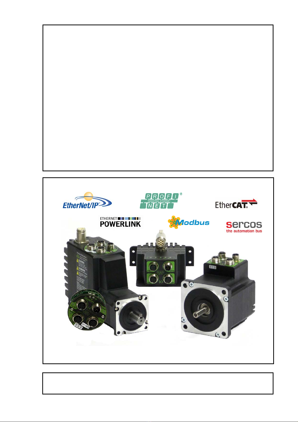
1.2 Module types .................................................................................................................................................... 10
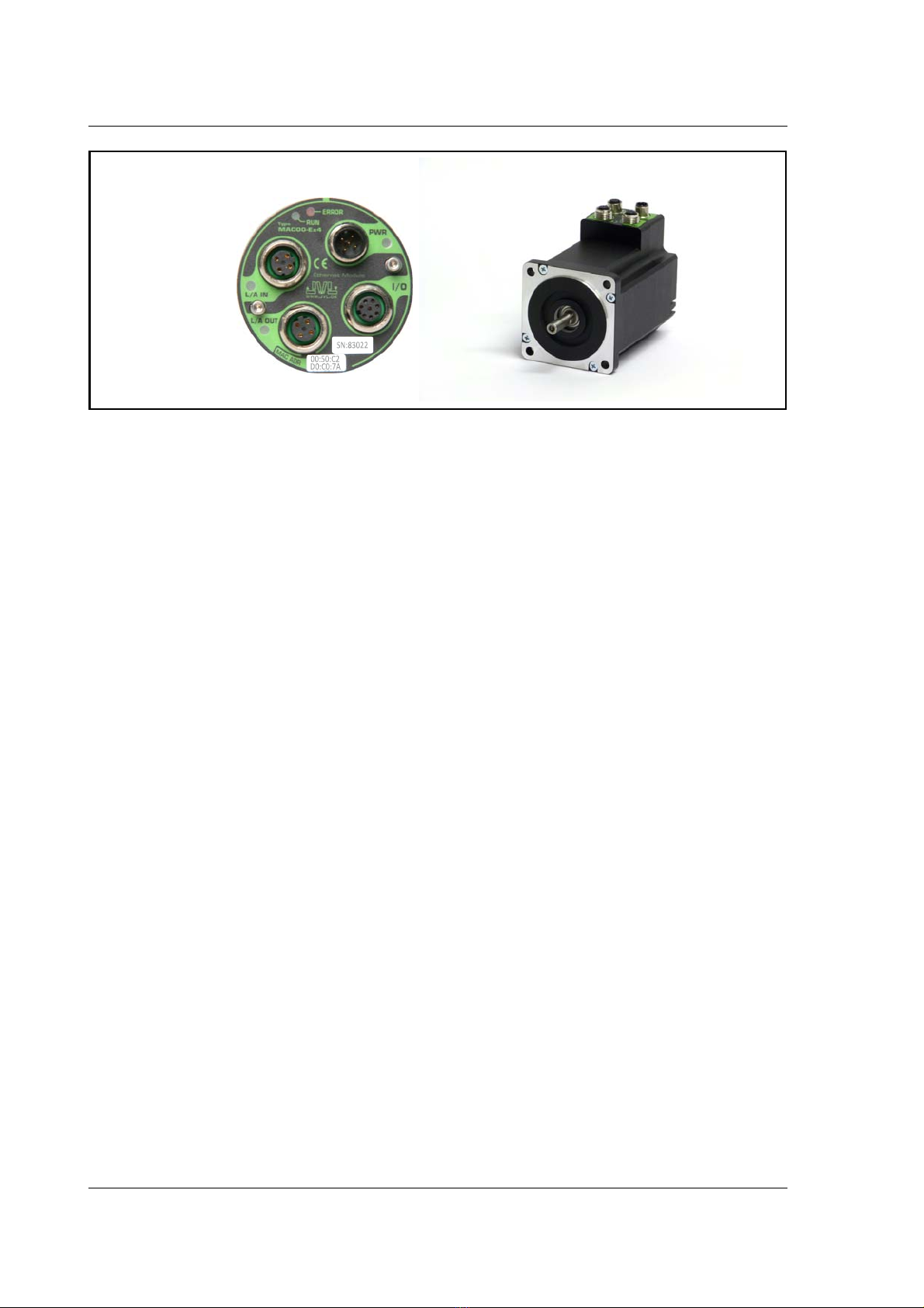
1.3 How to find FW/HW version at product .......................................................................................................... 13
2 General Hardware description ..................................................................................... 15
2.1 Hardware introduction ..................................................................................................................................... 16
2.2 I/O descriptions ................................................................................................................................................ 17
2.3 Connector description ...................................................................................................................................... 22
2.4 Cable accessories .............................................................................................................................................. 26
3 EtherCAT® Users Guide .............................................................................................. 33
3.1 Introduction to EtherCAT® ............................................................................................................................. 34
3.2 Protocol specifications ...................................................................................................................................... 36
3.3 Commisioning ................................................................................................................................................... 40
3.4 EtherCAT® objects .......................................................................................................................................... 45
3.5 CiA® DSP-402 drive profile ............................................................................................................................. 53
3.6 Examples ........................................................................................................................................................... 73
4 EthernetIP Users Guide ................................................................................................ 79
4.1 Introduction to EthernetIP ................................................................................................................................ 80
4.2 Using none cyclic messages .............................................................................................................................. 83
4.3 Using cyclic I/O-messages ................................................................................................................................. 88
4.4 Commissioning ................................................................................................................................................. 92
4.5 Implementation guidelines ................................................................................................................................ 99
4.6 Configuration with explicit messages .............................................................................................................. 102
4.7 Using and Selecting an Ethernet switch .......................................................................................................... 105
4.8 Examples ......................................................................................................................................................... 106
4.9 ODVA Conformance Certificate .................................................................................................................... 112
5 POWERLINK Users Guide .......................................................................................... 113
5.1 Introduction to POWERLINK ......................................................................................................................... 114
5.2 Protocol specifications .................................................................................................................................... 117
5.3 Commissioning ............................................................................................................................................... 121
5.4 Ethernet POWERLINK objects ....................................................................................................................... 124
5.5 Network Management Services ...................................................................................................................... 129
5.6 XML Device Description File ......................................................................................................................... 130
5.7 Examples ......................................................................................................................................................... 131
6 PROFINET Users Guide ............................................................................................. 137
6.1 Introduction to PROFINET IO ....................................................................................................................... 138
6.2 Commissioning ............................................................................................................................................... 140
6.3 PROFINET objects ......................................................................................................................................... 146
6.4 Ethernet switch ............................................................................................................................................... 153
6.5 Examples ......................................................................................................................................................... 154
7 ModbusTCP/IP® Users Guide .................................................................................... 159
7.1 Introduction to Modbus TCP/IP® .................................................................................................................. 160
7.2 Commissioning ............................................................................................................................................... 162
7.3 Register access ................................................................................................................................................ 170
7.4 Examples ......................................................................................................................................................... 171
8 Sercos® .......................................................................................................................177
8.1 Introduction to SERCOS ................................................................................................................................ 178
8.2 Commisioning ................................................................................................................................................. 180
8.3 Sercos Communication ................................................................................................................................... 196
8.4 FSP Drive profile ............................................................................................................................................. 207
8.5 FSP IO / JVL profile ......................................................................................................................................... 216
8.6 Examples ......................................................................................................................................................... 218

6 JVL Industri Elektronik A/S - User Manual - Integrated Stepper Motors MIS23x, 34x, 43x
9 Module Registers ........................................................................................................ 225
9.1 Register Overview ...........................................................................................................................................226
9.2 Register Descriptions. ......................................................................................................................................227
10 Using MacTalk over Ethernet .................................................................................... 239
10.1 Using MacTalk over Ethernet ..........................................................................................................................240
10.2 Setting up the Ethernet at the PC ...................................................................................................................243
10.3 Setting up MacTalk for Ethernet .....................................................................................................................249
11 Examples common to all protocols ............................................................................ 253
11.1 Using module I/O in embedded RxP ...............................................................................................................254
12 Appendix ..................................................................................................................... 257
12.1 Technical Data .................................................................................................................................................258
12.2 Motor registers MAC050 - 141 .......................................................................................................................264
12.3 Motor registers MAC400 - 4500 .....................................................................................................................273
12.4 Motor registers MISxxx ...................................................................................................................................292

JVL Industri Elektronik A/S - User Manual - Ethernet expansion modules for MAC motors 7
1 Introduction

8 JVL Industri Elektronik A/S - User Manual - Ethernet expansion modules for MAC motors
1.1 Introduction
Industrial Ethernet is becoming more and more
popular as it offers
• Very fast response time
• Predictable delay times (deterministic protocol)
• Safe transmission of data
Compared with most of the “classic” non Ether-
net based protocols the indstrial Ethernet offers
state of the art performance.
The MAC00-Ex4/-Ex41 (Ethernet module for
MAC motors) and MIS/MILxxxxxxExxxxxx (MIS/
MIL motors with Ethernet option) can be config-
ured by the end user to a number of different
Ethernet protocols, for instance
• EtherCAT®
• EtherNetIP®
• Ethernet POWERLINK®
• PROFINET IO®
• Modbus TCP/IP®
• Sercos®
• And more to come
Main Features:
• High speed communication - 100Mbits/sec.
• 2 individual ports on the module offers Daisy
chaining possibility.
• Standard M12 circular industrial connectors
• MAC motor module MAC00-Ex4: 1Digital
input (24V) and 1digital output (24V) for lo-
cal use around the motor
• MAC motor module MAC00-Ex41:4Digital
input (24V) and 2digital outputs (24V) for
local use around the motor
• MIS/MIL motor with Ethernet option offers 8
digital I/O’s. Each I/O terminal can also be an
analog input
• Multiple alternative I/O possibilities available
on request (OEM applications)
• LED’s for easy monitoring of operation sta-
tus
• Optional encoder I/O
• Rough design
• Access to all internal motor parameters and
registers possible. No need of pre-setup of
the motor.
• RS232 connection available for monitoring
and setup use for the MAC00-Ex4/-Ex41
modules.
• RS485 connection available for monitoring
and setup use for the MIS/MILxxxxxxExxxx
motor.
TT3001-02GB
MAC family
Ethernet for servos
MIS family
Ethernet for steppers

JVL Industri Elektronik A/S - User Manual - Ethernet expansion modules for MAC motors 9
MAC800 users important: Please notice that only MAC800 motors with a serial number newer than
85000 is compatible with the Ethernet modules MAC00-Exx.

10 JVL Industri Elektronik A/S - User Manual - Ethernet expansion modules for MAC motors
1.2 Module types
1.2.1 Module types (Only applicable for MAC00-Ex4/-Ex41)
The MacMotor Ethernet modules are available for several Ethernet protocols.
The module used for each protocol has its own unique type number, but is based on the
exactly same hardware.
A neutral module where no protocol is installed however also exist.
• Neutral module - no protocol installed.
MAC00-Ex4/-Ex41 is a neutral module not setup-up for any particular protocol. The
final user can setup it up for any of the available protocols just by using the general
MacTalk windows software.
The visible LED marking, labels etc. only states that its a neutral MAC00-Ex4/-Ex41
module.
• Pre-loaded module - a specific protocol has been installed.
The modules MAC00-EC4/-EC41 (EtherCAT), MAC00-EI4/-EI41 (EtherNetIP), and
MAC00-EL4/-EL41 (POWERLINK), MAC00-EP (Profinet), MAC00-EM (Modbus
TCP) are setup at delivery with the relevant protocol and also the right LED marking.
The final user can setup it up for any of the available protocols just by using the gen-
eral MacTalk windows software.
The visible LED marking, and type number is unique for each module type.
All modules (when not delivered mounted in a MacMotor) is followed by a little label
sheet containing labels for all the available standards and standards to come.
The overall idea is that any module can be changed to another protocol if desired, the
modules can stay neutral when it passes the distribution channel and be setup by the end-
user simplifying the logistics.
MAC800 users important:
Please notice that only MAC800 motors with a serial number newer than 85000 is com-
patible with the Ethernet modules MAC00-Exx.
1.2.2 How to change the protocol type
Only 2 steps are needed in this process.
1. Install the intended protocol firmware in the module.
2. Apply or changing the label with LED marking and type number of the module.
The firmware can be setup as follows
(see next page)

JVL Industri Elektronik A/S - User Manual - Ethernet expansion modules for MAC motors 11
1.2 Module types
TT3039-02GB
Step 1
Determine which Ethernet protocol you want to use.
Have in mind that your Ethernet module may
already be setup for a protocol.
How to setup the module for a different/new protocol
Step 2
As shown the module is setup as a module with
the Ethernet Powerlink protocol.
Choose the in the U
menu to setup the module with another protocol.
Update Firmware pdates
Step 3
Make sure that the checkbox
is checked.
Select the desired firmware such as EtherNet-IP.
Note that there may exist more than one
version. Choose the newest version.
Press S to download the selected firmware.
The status counter will now rise from 0
to 100%.
“Show all files”
tart
Step 4
When the download process is finished, the status
shows “ .
Also “ has changed to the actual
downloaded version meaning that the firmware in
the module is now changed permanently.
Done”
Current version”
Step 5
The module tab has now changed from
Powerlink (EL) to EthernetIP (EI).
Step 6
The firmware version, MAC address etc.
can be monitored on the module tab.
! When changing protocol the module
factory defaults are restored.

12 JVL Industri Elektronik A/S - User Manual - Ethernet expansion modules for MAC motors
1.2 Module types
Changing the label and typenumber (only MAC products)
This illustration show how to apply the appropriate label in order to change the LED
texts and also give the module its unique typenumber after the protocol firmware is load-
ed.
Changing the label and typenumber (only MIS/MIL products)
No changes need to be done at the MIS/MIL motors. The LED at the rear is universal.
Typenumber overview for MAC and MIS/MIL:
MAC Type MIS Type Ethernet Protocol
MAC00-EC4/-EC41 MIS/MILxxxxxxECxxxxx EtherCAT
MAC00-EI4/-EI41 MIS/MILxxxxxxEIxxxxx EtherNET / IP
MAC00-EL4/-EL41 MIS/MILxxxxxxELxxxxx EtherNet POWERLINK
MAC00-EM4/-EM41 MIS/MILxxxxxxEMxxxxx Modbus TCP
MAC00-EP4/-EP41 MIS/MILxxxxxxEPxxxxx Profinet IO
MAC00-ES4/-ES41 MIS/MILxxxxxxESxxxxx Sercos III
Only MAC
Sheet with type labels
for each Ethernet protocol
Peel off the relevant label from the sheet.
and place it in this area.
The existing typenumber and LED texts
will thereby be overwritten/replaced.
TT3040GB

JVL Industri Elektronik A/S - User Manual - Ethernet expansion modules for MAC motors 13
1.3 How to find FW/HW version at product
1.3.1 Check Ethernet module version.
The firmware and hardware version of the Ethernet MAC module or the integrated
Ethernet module in the MIS/MIL motor can be checked from the MacTalk software when
connected to the motor. Select the tab for the Ethernet protocol in use, and check the
“Module info” frame. For some protocols and some motors is also the minimum capable
cycle time when using a drive profile (CiA402, FSP Drive etc.) listed.
1.3.2 Check motor version.
The hardware version of the motor can be found using MacTalk. Move the mouse curser
to the lower left corner and a pop-up box will show with all the relevant info.
The firmware version in the motor can be seen at the green text in the bottom of the
picture.
TT3113-01GB
TT3114-01GB
HW version
FW version

14 JVL Industri Elektronik A/S - User Manual - Ethernet expansion modules for MAC motors

JVL Industri Elektronik A/S - User Manual - Ethernet for MAC and MIS motors 15
2 General Hardware description Only MAC

16 JVL Industri Elektronik A/S - User Manual - Ethernet for MAC and MIS motors
2.1 Hardware introduction
2.1.1 Overall hardware description
All internal and external main connections can be seen in the illustration below.
P+
CVI
P+
P-
P-
5V
O+
IN1
IO
-
O1
Rx1P
Rx0P
Rx1N
Rx0N
Tx1P
Tx0P
Tx1N
Tx0N
Tx
Rx
O1
Fx4
IO1 4-
Fx1 3-
RX
O2
A1/B1
A2/B2
TX
GND
GND
4 Inputs
4
3
4
2 Outputs
RS232
serial interface
Control
core
incl
8Mb RAM
4Mb Flash
Power supply for the module
“PWR”
Power supply
MAC400/800: +24V
“I/O”
Digital inputs and outputs
Voltage range 5-28 (32)V
“L/A IN”
Primary
EtherNet
Interface
M12 female
connector
“L/A OUT”
Secondary
EtherNet
Interface
M12 female
connector
TT3003GB
MAC00-Ex4 expansion module Basic MAC motor
(MAC400 or 800)
Power supply
Internal power supply
(processor and encoder)
Multifunction I/O1
(setup as “serial data”)
Multifunction I/O2
High speed sync. 0/1
Optional I/O use
Internal COM
Status outputs
Asynchronous
interface (5V)
AIN1
AIN2
Analogue inputs
AIN1=Zero search input
±10V nom. or up to 32V
8
2
2
2
2
3
3
3
3
4
4
4
4
6
5
5
7
1
1
1
1
See note1
See note1
See note1
See note1
Note1: These signals are internally avilable. Custom hardware can be made
for OEM appl. with other connectors in order to make the signals available.
Contact your JVL representative for more information.
Optocoupler
Isolation zone 2
Each isolation zone do not have galvanic contact with any other circuitry.
Isolation zone 3
Isolation zone 4
Only MAC

JVL Industri Elektronik A/S - User Manual - Ethernet for MAC and MIS motors 17
2.2 I/O descriptions
2.2.1 Hardware overview
2.2.2 External signals available at the MAC00-Ex4 and Ex41.
Following signals are available.
• “L/A IN” and L/A OUT” connector.
- The Ethernet connection. L/A IN is connected to the upstream master and L/A
OUT can be used downstream for the next motors/units in the chain.
• “I/O” connector.
- AIN1 - analogue input +/-10V.
Can be used as input for the zero search sensor or as general analog input for
speed or torque control depending on the what the actual operation mode in the
motor has been setup for.
MAC00-Ex41 offers a second analogue input AIN2. Function similar to AIN1.
Please notice that AIN2 is not available if mounted in a MAC050-MAC141.
-O1-useroutput1
Can be used as or as general output control able over the Ethernet interface.
MAC00-Ex41 offers a second digital output (O2). Function similar to O2.
-RS232Interface.
Serial unbalanced interface for connection to a PC or a controller. The protocol
is similar to the USB or RS485 interface, which means that all registers/parame-
ters in the motor can be monitored or changed. RS232 is not recommended for
long distances (>10m).
-IN1-Userinput1.
Can be used as general input which can be read over the Ethernet interface.
MAC00-Ex41 offers in total 4 digital inputs (IN1, IN2, IN3 and IN4).
Only MAC
Expansion module MAC00-Ex4 and Ex41 front plate
Neutral module for all the Ethernet protocols
L/AIN
PrimaryEthernet
channelM12‐4pin
female(D‐coded)
andLEDforshowing
activity.
L/AOUT
SecondaryEthernet
channelM12‐4pin
femaleEthernetcoded
(Dcoded)Usedwhen
moduleisdaisychained
MACAddress
Eachmoduleishavingitsown
uniqueMACaddressused
toidentifyitontheEthernet
network.TheMACaddresscanalsobereadelectronically
TT3038-02GB
PWR
Powersupplyconnector
M12‐5pinmaleand
GreenLEDforindicating
powerapplied
Modulestatusindicators.
(MAC00‐Ex4shown)
I/O
I/O’sandRS232interface
(basicversion)
M12‐8pinfemale
1
(ext.verison)
M12‐17pinfemale
4digitalinputsand2digital
outputs,2analogueinput
2RS422/RS485channels
MAC00‐Ex4
MAC00‐Ex41
digitalinputand1digital
output,1analogueinput
Serialnumber
Eeachmodulehaveitsown
uniqueserialnumberwhich
canbeusedfordetermine
hardwareversionetc.

18 JVL Industri Elektronik A/S - User Manual - Ethernet for MAC and MIS motors
2.2 I/O descriptions
- I/O supply and gnd (IO- and O+).
Used as ground and supply for the user in/output (O1 and IN1).
- 2 RS422/RS485 Multifunction I/O channels
Only available at the MAC00-Ex41. Can be used for encoder input, full duplex
serial communication, encoder output etc.
Please notice that no multifunction I/O’s are available if mounted in a MAC050-
MAC141.
• “PWR” connector.
- 24V supply for the internal control circuitry in the motor.
Only MAC

JVL Industri Elektronik A/S - User Manual - Ethernet for MAC and MIS motors 19
2.2 I/O descriptions
2.2.3 General power supply description
The Ethernet modules can be used in the allmost all the MAC motors but please be
aware that to use the MAC50 to 141 they will need the special option : “A009” for ex-
ample “MAC140-A1-AAAA-A009”
. The diagram below shows how to connect power to a MAC400 motor mounted with
a MAC00-Ex4/-Ex41 module. Please notice that the voltage connected to P+ and/or CVI
must stay in the range +12-26VDC. When using a MAC50 to 141 up to 48VDC is al-
lowed.
See also the general power supply description in the MAC motor main manual LB0047.
For further information concerning physical connections, see the Expansion module
MAC00-Ex4 (basic version) connector description, page 22.
Only MAC
TT3011GB
MAC400 Motor
with MAC00-Ex4
MAC400 Motor
with MAC00-Ex4
P+
P+
P-
P-
CVI
CVI
Power
Supply
Power
Supply
Control Volt.
Control Volt.
Mains 115 or 230VAC
Mains 115 or 230VAC
Main supply
Main supply
Max. 26VDC !
Max. 26VDC !
It is recommended
that a separate supply
line is used for each motor.
Power supply
Make sure that all
involved units are
connected to the same
potential
GND
+12-26VDC
(control voltage)
Power supply connections to a MAC400
mounted with a MAC00-Ex4 module.

20 JVL Industri Elektronik A/S - User Manual - Ethernet for MAC and MIS motors
2.2 I/O descriptions
2.2.4 Using the analogue input 1 and 2 (AIN1 and AIN2).
When a MAC00-Ex4 or MAC00-Ex41 module is mounted in the MAC motor, the ana-
logue input(s) is available in the same manner as in the basic motor itself.
The analogue input(s) can be used for several applications and the function of the ana-
logue input is determined by the mode in which the motor is set to operate.
Typically the input(s) is used for controlling the velocity, torque or position of the motor
but the input is also used as digital input for zero search or in “Air Cylinder Mode” where
it is used as trigger input for the movement done by the motor.
For further information concerning physical connections, see the Expansion module
MAC00-Ex4 (basic version) connector description, page 22.
Please notice that analogue input 2 (AIN2) is only available at MAC00-Ex41. Please no-
tice that AIN2 is not available if mounted in a MAC050-MAC141.
Only MAC
TT3012-02GB
MAC motor
+MAC00-Ex4
or MAC00-Ex41
MAC motor
+MAC00-Ex4
or MAC00-Ex41
MAC motor
+MAC00-Ex4
or MAC00-Ex41
Make sure that all
involved units are
connected to the same
potential
Make sure that all
involved units are
connected to the same
potential
Make sure that all
involved units are
connected to the same
potential
Analogue input connection at the MAC motor
mounted with a MAC00-Ex4 or Ex41 module.
Note ! : screen only
connected to signal source.
Note ! : screen only
connected to signal source.
±10V out AIN1
(analogue input)
AIN1
(analogue input)
AIN1
(analogue input)
GND
(ground)
GND
(ground)
GND
(ground)
Position or
velocity
controller
Power supply
10-32VDC
Power supply
10VDC
Ground
Screen
Screen
Connected to a external controller
Connected to a potentiometer
Connected to a zero search switch
Zero search switch
Note: Do not apply voltages higher than 32V to the analogue input (AIN)
If only 24V supply is available
insert a 2.7k resistor here.
This example only covers 0-10V but other configurations do of course also exist, such as 0-5V or +/-10V.
2kOhm potentiometer
(JVL typeno. “POT2K”)
AIN2
(only MAC00-Ex41)
AIN2
(only MAC00-Ex41)
AIN2
(only MAC00-Ex41)
This manual suits for next models
11
Table of contents
Popular Industrial Equipment manuals by other brands

SMC Networks
SMC Networks EX260-SCA1-X176 Installation and maintenance manual

TEDA
TEDA XQ140 Parts and operation manual

GE
GE MicroVersaTrip Plus installation instructions

Eaton
Eaton DILP-XHB Series Instruction leaflet

ekwb
ekwb EK-FC295 GTX INSTALLATION AND MOUNTING MANUAL

Ocean
Ocean VH200 operating manual

PCB Piezotronics
PCB Piezotronics 1203-11A Installation and operating manual

Jäger
Jäger Z80-K450.16 S4 manual

ixtur
ixtur MAP-6 Product instructions

api technologies corp.
api technologies corp. 4205A Series Operation and installation manual

ABB
ABB HT576073 Operation manual

CAB
CAB 4214 Series Service manual