JYC Power Group MeriTech Meritsun LFP50-48 User manual

Lithium-ion Battery Pack
Model: LFP50-48 & LFP100-48
User manual
Lithium Energy Solution
1/23

Please comply with all warnings and operating
instructions in this manual strictly. Save this manual
properly and read carefully the following instructions
before installing the unit. Do not operate this unit before
reading through all safety information and operating
instructions carefully.
2/23

Safety Precaution
1. When Using battery
Danger of High Voltage:
The high voltage power supply offer the equipment power, wet object contact high voltage power
supply directly or indirectly, can cause fatal danger.
Static‐free:
Static electricity would damage veneer on the electrostatic sensitive components, before touching the
plug‐in, circuit board or chips, be sure to use correct electrostatic prevention measures.
Dc short circuit dangerous:
Power system provides dc regulated power supply. Dc short circuit could cause fatal damage to the e
quipment.
Using a special tool :
Working in high voltage and ac power, be sure to use a special tool instead of individual tools.
Disconnect the power supply in operation:
When operate the power supply, you must first cut off power supply, power operation is prohibited.
3/23

2. While Charging
CAUTION
The temperature range over which the battery can be charged is 0°C to 45°C. Charging the battery
at temperatures outside of this range may cause the battery to become hot or to break. Charging the
battery outside of this temperature range may also harm the performance of the battery or reduce
the battery’s life expectancy.
3. When Discharging the Battery
DANGER
Do not discharge the battery using any device except for the specified device. When the battery is
used in devices aside from the specified device it may damage the performance of the battery or
reduce its life expectancy, and if the device causes an abnormal current to flow, it may cause the
battery to become hot and cause serious injury.
CAUTION
The temperature range over which the battery can be discharged is -20°C to 60°C. Use of the battery
outside of this temperature range may damage the performance of the battery or may reduce its life
expectancy.
4/23

1. Basic Block Diagram
•There are Battery cells and BMS board inside, before connecting the terminal, please read the diagram, and
make sure the output is no short or other abnormal connection.
Fig1 Battery Block Diagram
2. Installation and Operation
2-1. Unpacking and Inspection
Unpack the package and check the package contents. The shipping package contains:
●One Battery
●Two mounting bracket
●A small bag of screws and nuts
NOTE: Before installation, please inspect the unit. Be sure that nothing inside the package is damaged
during transportation. Do not turn on the unit and notify the carrier and dealer immediately if there is any
damage or lacking of some parts. Please keep the original package in a safe place for future use.
5/23

2-2. Panel View
No. Description Functional Description
1 Output MCB Positive terminal
2 Output terminal +/-
3 Reset key On/OFF button
4 RS-485connection port-B RS485 RS485 communication interface
5 RS-485connection port-A RS485 RS485 communication interface
6 RS-232 connection port RS232 RS232 communication interface
7 Display connection address ADS Dialer
8 Red- trouble-light on Run indicator light OFF
9 Display the battery's capacity Electricity volume indicator
10 Display state information ALM alarm indicator light blinking
2-3. Single battery Installation
Installation and wiring must be performed in accordance with the local electric laws/regulations and
execute the following instructions by professional personnel.
1) Make sure the mains wire and breakers in the building are in compliance with the standard of rated
capacity of battery to avoid the hazards of electric shock or fire.
NOTE: Do not use the wall receptacle as the input power source for the battery, as its rated current is
less than the battery’s maximum input current. Otherwise the receptacle may be burned and destroyed.
2) Switch off the mains switch in the building before installation.
3) Turn off all the connected devices before connecting to the battery.
4) Prepare wires based on the following table:
6/23

Model Cables(AWG) Cables(mm2)
<50Ah 8 6
50Ah 6 16
100Ah 4 25
Table 1 Output Cables
NOTE 1: It is recommended to use suitable wire in above table or thicker for safety and efficiency.
5) Put the terminal block cover back to the front panel of the battery.
NOTE: Set the battery pack breaker in “OFF” position and then install the battery pack.
2-4. Software Installation
For optional computer system protection, install battery monitoring software to fully configure battery
shutdown and other setting value.
2-5. Installation of Battery in Parallel
2-6 Installation Precautions
(1) Prior to installation, unpacking to check the quantity of the parts and battery appearance;
(2) Install the hanger and handle and measure the battery voltage with a multimeter. The general factory voltage of the
battery is 51.5V-53.5V;
(3) Prior to wiring, check the anode and cathode of the battery and the anode and cathode terminals shall not be
connected reversely;
7/23

(4) During battery connection, please wear the protective gloves. When using such metal tools as torque wrench, please
perform insulating packaging for them and two end of the metal tools such as torque wrench shall not contact the positive
and negative terminals of the battery at the same time to avoid battery short-circuit;
(5) Before the battery is connected with the externally connected equipment, make the equipment in a disconnected state,
check whether the connecting polarity of the battery and total voltage are correct, connect the battery anode with the
equipment anode and battery cathode with the equipment cathode and fix the connecting line;
(6) During handling and placement, the battery must be handled gently. No dropping or impacting. The battery shall not be
thrown or beaten to avoid damaging the battery or resulting in potential safety hazard;
(7) Do not touch the surface of the battery box with the sharp part of the tool to scratch or damage the battery box;
(8) Do not disassemble the battery box without authorization;
(9) Do not put any article made of the metal conductive material together with the battery or assemble it into the battery
box;
(10) Install it according to the selected installation mode:
Installation of standard cabinet (rack): Install the matching hanger for the battery pack and fix them in the standard
cabinet and the tray protection is added for the battery box.
Installation of wall-mounted box: Prior to installation, please ensure that the wall complies with the wall-mounted
requirements; according to the location in the design plan, install the special wall-mounted box of the lithium battery;
the battery pack is fixed in the wall-mounted box in a hanger manner;
Installation of integrated indoor and outdoor cabinets (boxes): Install them according to the installation specification
for the customized integrated cabinet (box).
8/23

2-7 Operation Instruction for Installation
1) Prior to installation, please check whether the battery is normal.
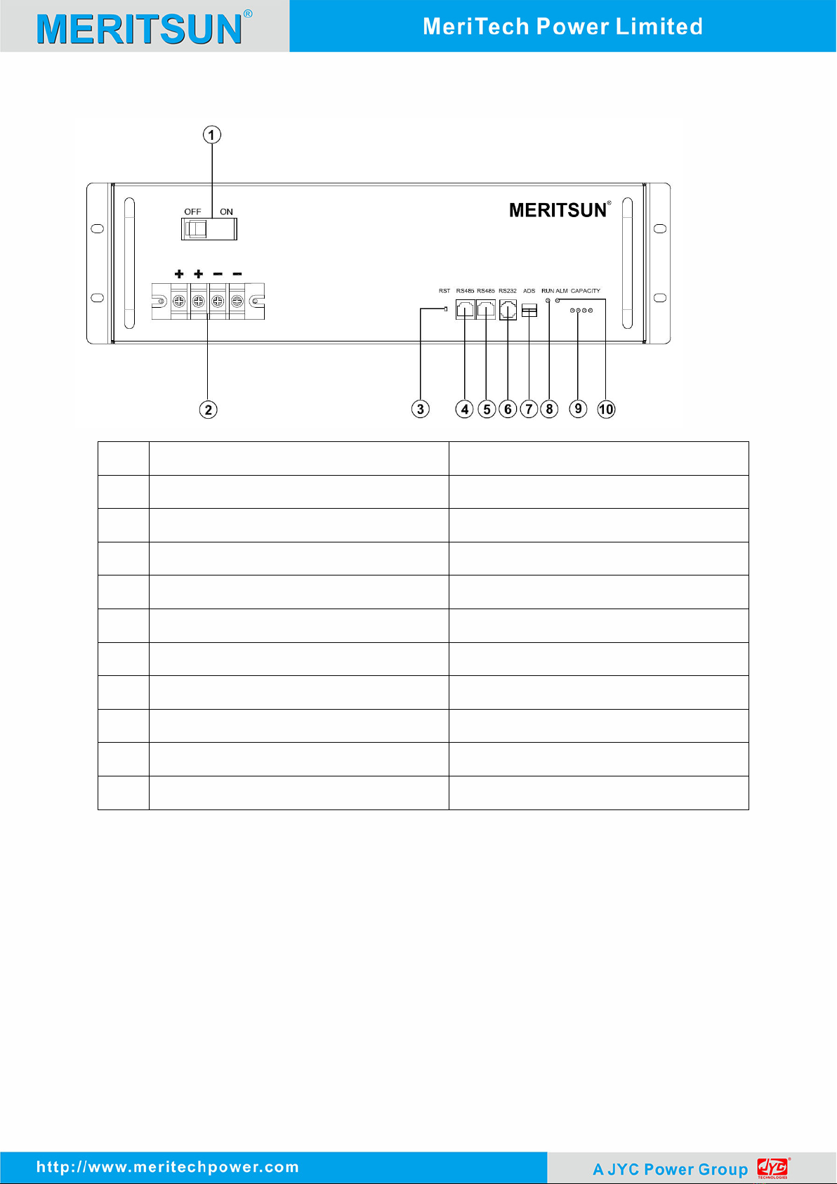
Press the reset key RST on the front panel for 3S for startup. During startup, 4 capacity indicator lights on the
front panel, ALM alarm indicator light (red) and RUN running indicator light lights up. Check whether all indicator
lights light up normally; then the ALM alarm indicator light goes out, the RUN running indicator light lights up and
the capacity indicator light lights up according to the capacity.
If the ALM alarm indicator light flashes after startup, it means that the battery has an alarm. The newly installed
battery seldom has alarm. The common alarm is the battery undervoltage alarm (which is resulted from non-use of
the battery for a long time). Such case may be removed after the battery is charged for 30min; if the alarm may not be
removed, please press the reset key RST for 10S, until all LEDs light up for reset, execute the battery reset operation
and confirm whether the alarm is removed. If the alarm is removed, the battery may be used normally. Otherwise the
battery shall be reworked.
2) For the battery which is normal after detection, please press the reset key RST for 3S to execute the battery
ON/OFF operation.
Instructions of
manual
operation of
the reset key
RST
Startup In the OFF state of BMS, press the key for 3S for
startup;
Shutdow
n
In the non-standby state of BMS, press the key for
3S for shutdown;
Reset In the non-standby state of BMS, press the key for
10S, until all LEDs light up for reset.
Instructions: “Shutdown” and “standby” and “startup” and “activation” in Chinese have the same meaning;
3) Installation of the lithium battery, wiring and startup.
Make the battery pack in a standby state, install it in the battery cabinet one by one, the anode and cathode of the
battery pack are connected respectively, which are connected to the switching mode power supply or UPS (Please
note that the switching mode power supply and UPS shall be disconnected from the AC). Press the reset key RST of
one of battery packs for 3S for startup. Such startup battery may activate other batteries which are connected in
parallel (or press the reset key RST of each battery pack for 3S successively) and the whole battery pack with high
capacity enters the working state. Later, apply AC to the power supply equipment such as switching mode power
supply and UPS to make the whole standby system run.
The specification of the connecting line is selected according to the load current, with the common
specifications of the connecting line as follows:
9/23

1) When the battery pack with the capacity of 200Ah or below is connected in parallel, it is
suggested to select 16mm2 copper wire.
2) When the battery pack with the capacity of 200Ah~300Ah is connected in parallel, it is
suggested to select 16mm2 or 25mm2 copper wire.
3) When the battery pack with the capacity of 300Ah or above is connected in parallel, it is
suggested to select 25mm2 copper wire.
Note: We do not equip with the battery connecting line by default, which shall be selected according
to the total capacity of the battery pack.
Lithium
battery
Copper core
cable Copper pigtail Remarks
48V50Ah 16mm2/25mm216-8/25-8
M8 copper pigtail is
used for 48V50Ah sing
pack of battery binding
post
48V100Ah 16mm2/25mm216-10/25-10
48V100Ah M10 copper
pigtail is used for
48V100Ah sing pack of
battery binding post
Introduction to operation steps in detail according to the capacity required:
•Battery pack in parallel with the capacity of 200Ah or below (the wiring diagram is
shown in Figure 1):
Step 1: Make the battery pack in the standby state and install it in the battery cabinet
successively;
Step 2: Disassemble the anode insulating cap of the neighboring batteries one by one, connect
the anodes of up and own neighboring battery packs with the installation connecting line and screw
on the anode insulating cap;
Step 3: According to step 2, connect the cathode of the battery pack;
Step 4: Set the dial-up addresses of all battery modules from top to bottom one by one, which
are 1000, 0100, 1100 and 0010 (the dial-up addresses are set according to the number of battery
modules actually used) respectively; (this step may be skipped if there is no need to access to the
remote monitoring platform);
Step 5: Perform the cascade connection to RS485 communication interface of the battery
module with the RS485 connecting line; lead to the collector of the monitoring platform from the
RS232 interface of the battery module with the address of 1000 with the RS232 connecting line; (this
step may be skipped if there is no need to access to the remote monitoring platform);
10/23

Step 6: Draw out two wires from the anode and cathode of a battery pack at the top or in the
middle respectively as the main connecting line of the battery pack in parallel, which are connected
with the switching mode power supply or UPS.
Step 7: Press the RST key of each battery pack for Reset and the whole battery pack with high
capacity enters the working state.
Wiring Diagram of Battery Pack in Parallel with Capacity of 200Ah or Below
•Battery pack with the capacity of 200Ah~300Ah in parallel:
Step 1: Make the battery pack in the standby state and install it in the battery cabinet
successively;
Step 2: Disassemble the anode insulating cap of the battery pack one by one, connect the anode
of each battery pack to the anode busbar at the battery cabinet side with the installation connecting
line with the same length and screw on the anode insulating cap;
Step 3: According to step 2, connect the cathode of the battery pack;
11/23

Step 4: Set the dial-up addresses of all battery modules from top to bottom one by one, which
are 1000, 0100, 1100 and 0010 (the dial-up addresses are set according to the number of battery
modules actually used) respectively; (this step may be skipped if there is no need to access to the
remote monitoring platform);
Step 5: Perform the cascade connection to RS485 communication interface of the battery
module with the RS485 connecting line; lead to the collector of the monitoring platform from the
RS232 interface of the battery module with the address of 1000 with the RS232 connecting line; (this
step may be skipped if there is no need to access to the remote monitoring platform).
Step 6: Draw out two wires from the anode and cathode of a battery pack at the top or in the
middle respectively as the main connecting line of the battery pack in parallel, which are connected
with the switching mode power supply or UPS.
Step 7: Press the RST key of each battery pack for Reset and the whole battery pack with high
capacity enters the working state.
Wiring Diagram of Battery Pack in Parallel with Capacity of 200Ah~300Ah
12/23

2-8. Circuit breaker of battery circuit is set to OFF, connect it to switch power supply, and output voltage
of switch power supply is set to 52.5-54V/56-57.6V, current set to 0.2C; after all settings done, switch the
circuit breaker ON.
2-9. Communication of battery
6-9-1 Single battery communication
6-9-2 Connection mode for parallel communication
While in parallel communication, dial-up addresses of battery module are 1,2,3,4……14,15,of which
1 stands for host computer, to which other batteries’data is uploaded; host computer conducts
unified uploading, and host computer with dial-up code of 1 is required to connect with upper
computer; FF polling mode used as consulting mode.
RS232 Parallel Communication
13/23

RS485 Parallel Communication
2-10. Monitor Software interface
14/23

6-11 Upper machine instructions
A、Software source file:
Name of software source file:BmsTools.exe、BmsTools.exe.config、Language.xml、
LogParams.xml、MultiLanguage.dll、ParamSetting.xml six documents in total。
B、Software running environment:
The software running on the PC and its compatible computer, using WINDOWS operation system.
C、Software using steps:
(1)Double click BmsTools.exe icon can show the main interface of the software(As shown in
figure A).
15/23

Figure A:Real-time Monitoring
(2)Open the main interface(As shown in figure A),the software automatically search serial
port,and automatically open,real-time read battery voltage, power, temperature, and protection of
the state of battery parameters.
Operating authority is divided into general rights and administrator privileges。
(3)In the display record TAB(As shown in figure B),there are two checkboxs, display and automatic
storage.
Check the display option, can real-time display the various parameters of the battery.
16/23

Check the automatic storage option, can automatically storage the parameters of the battery in the
excel table. The file in the software under the current file path of the data folder, storage file name
named after pack number and time.比For example packNo1_20150306145010.xls。
Figure B:Display record
(4)In storage record TAB(As shown in figure C),can read the battery protective plate storage of
records, the records content including record the protection and alarm and restore the category and
time of occurrence,records includes fault categories and fault occurs cell voltage, total voltage,
charge/discharge capacity, charge/discharge current, temperature, etc. In addition to normal record
protection and alarm and recovery information, but by setting, record battery parameters within a
certain period of time.:Cell voltage, total voltage, charge/discharge capacity, charge/discharge
current, temperature, etc.
17/23

Figure C: Storage record
(5)In the parameter settings TAB(As shown figure D),the TAB for the battery parameters.
Read the parameter I:Read all the parameters of the battery
Write in parameter: Write all the parameters of the battery
Restore default:Restore the default parameters for battery
Import parameters: Export the current battery parameters, for the XML file format.
Expo parameters:The parameters of the import file format for the XML to the current TAB
18/23

Figure D: Parameter Settings
(6)In the system configuration TAB(As shown in figure E),the TAB for battery calibration,
parameters setting, the battery calibration and setting up the battery system parameters
need administrator privileges.
Figure E: System Configuration
19/23

2-12Address Switch function(Only in Parallel)
When battery work in parallel, main pack and slave packs need address as follows:
6-13 Communication Function
Fig8 Communication Port Interface
RS485 Terminal Port Definition
Pin1,8 RS485_B
Pin2,7 RS485_A
Pin3,6 GND
Pin4,5 NC
RS485 Communication Port Definition
20/23
This manual suits for next models
1
Table of contents