Superb SB BIB LV12V350A User manual

Manual
BATTERY
INTERFACE BOX
12V/350A-600A
24V/350A-600A
48V/350A-600A
Version
February 2019

2
User Manual Battery interface box
Dear customer,
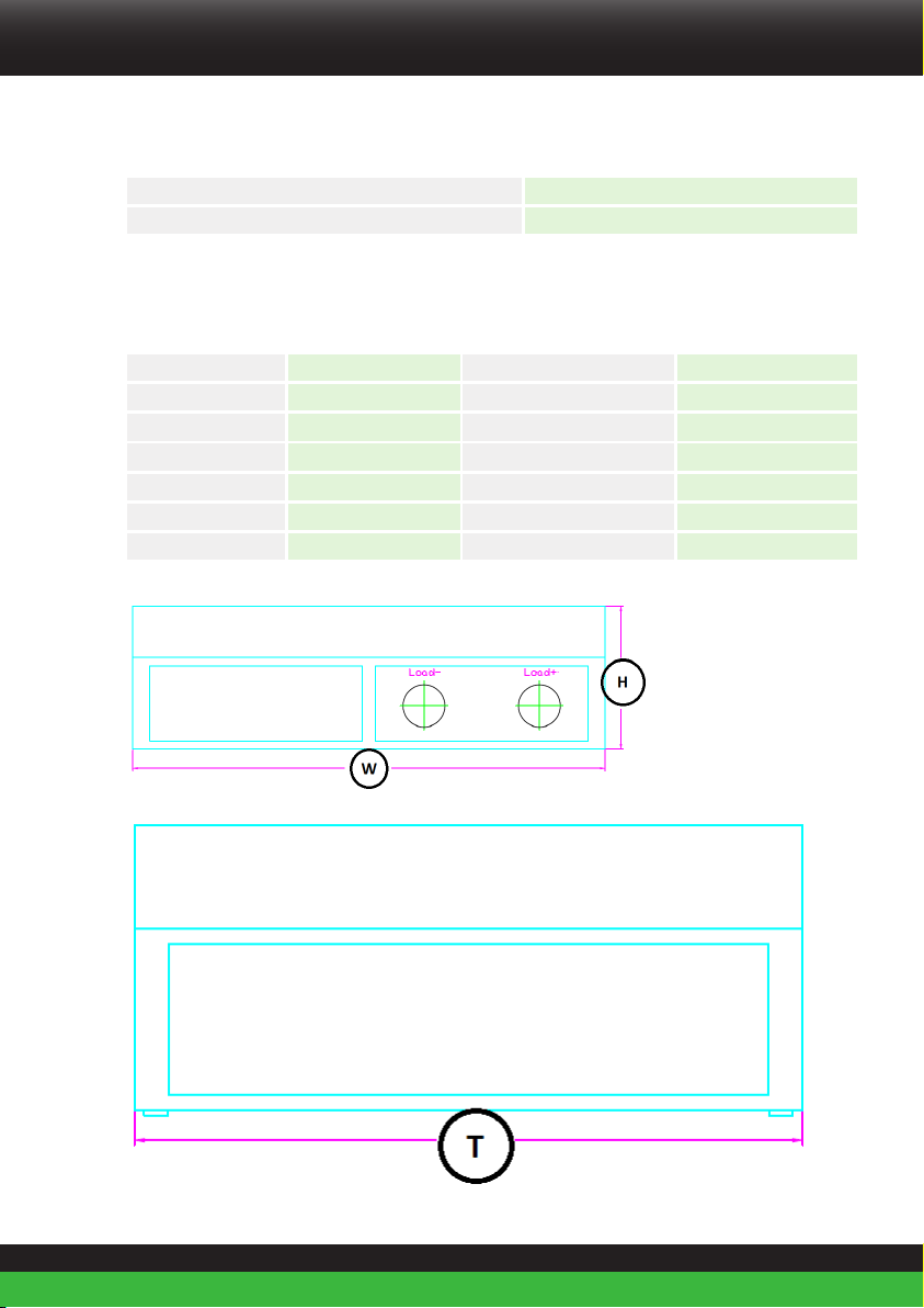
The Battery Interface Box (BIB) is a communication and control interface for Super B Lithium
Batteries.
The Battery Interface Box (BIB) is a device that gathers data from multiple
batteries and treats them as one single battery system. The BIB gathers data from all
connected batteries and can cut-off the system when errors are detected. It also manages
pre-charge and protocol conversions.
This manual contains all the information necessary to install, use and maintain the BIB. We
kindly ask you to read this manual carefully before using the product. This manual is meant
for the installer and the user of the BIB. Only qualied, certied personnel may install and
perform maintenance on the BIB. Please consult the index at the start of this manual to
locate information relevant to you.
The boundaries of its use, as described in this manual should always be upheld. The BIB may
not be used in medical or in aviation related applications. The BIB may not be used for any
purposes other than described in this manual. Using the BIB for any other purpose will be
considered improper use and will void the warranty of the product. Super B cannot be held
responsible for any damage caused by improper, incorrect or unwise use of the product.
Read and understand this manual completely before using the product.
During the use of the product, user safety should always be ensured, so installers, users,
service personnel and third parties can safely use the BIB. This is the original manual, keep it
in a safe location! Please consult www.super-b.com for the latest version of all manuals.
Copyright© Super B All rights reserved. Licensed software products are owned by Super B
or its subsidiaries or suppliers, and are protected by national copyright laws and international
treaty provisions. Super B products are covered by Dutch and foreign patents, issued and
pending. Information in this publication supersedes that in all previously published material.
Specications and price change privileges reserved. Super B is a registered trademark of
Super B

3
Be in charge Super B
For more information, or to order documents, contact:
Super B
Demmersweg 3
7556 BN Hengelo (Ov)
The Netherlands
Tel: +31(0)88 00 76 000 (support)
E-mail: support@super-b.com
www: www.super-b.com
Be in charge Super B

4
Table of content
1. Introduction 6
1.1. Product description 6
1.2. Glossary of Terminology 6
1.3. Used symbols 6
2. Product specifications 7
2.1. Product features 7
2.2. General product specications 7
2.3. Technical specications 7
2.3.1. Battery designation 8
2.3.2. Electrical properties (23°C) 8
2.3.3. Dimensions (±1mm) 8
2.4. Environmental conditions 9
2.4.1. Marine use 10
2.5. Required tools 10
2.6. Components 11
2.6.1. List of components 11
2.7. Connections, indicators and battery controls 11
2.7.1. Con1 (Output for BI-Stable Relay) 12
2.7.2. Con2 (I/O connection 7) 12
2.7.3. Con 3 (CANopen; 5-pin “micro” style connector) 13
2.8. Peripheral equipment 13
2.8.1. Obligatory 13
2.8.2. Optional Components 14
3. Safety guidelines and measures 15
3.1. General 15
3.2. Disposal 15
3.3. Safety symbols and markings on product 16
4. Installation 17
4.1. General information 17
4.2. Unpacking 17
4.3. Preparing the battery for use 17
4.3.1. Placement of the battery 17
4.3.2. Placement and removal of a fuse 18
4.4. Connection wires 19
4.5. Installing the mandatory Battery Disconnect device 19
4.5.1. Connecting a bi-stable relay to the Li-ion battery 19
4.5.2. Connecting a normal relay as Battery Disconnect device 20
4.5.3. Using the SB BIB (Battery Interface Box)
21

5
Be in charge Super B
4.5.4. Using the SB BCI-C1 (Battery Communication Interface) with a normal relay 21
4.6. Connecting the Li-ion battery to the load/charger 22
4.6.1. Connecting a single Li-ion battery to the load/charger with a bi-stable relay 22
4.6.2. Connecting a single Li-ion battery to the load/charger with a normal relay 23
4.6.3. Connecting Li-ion batteries in series. 25
4.6.4. Connecting Li-ion batteries in parallel 25
4.6.5. Connecting Li-ion batteries in series and parallel 26
4.7. CANopen interface 27
4.7.1. CAN Bus network topology 28
4.7.2. Termination Resistors 28
4.7.3. CAN balancing 29
5. Battery use 30
5.1. General information 30
5.2. Charging 30
5.2.1. Charging rate 30
5.2.2. Charging method 31
5.2.3. Battery balancing 33
5.2.4. Reading out the battery’s State of Charge (SoC) 33
5.3. Battery Monitoring Software 34
5.3.1. Battery History Recording 34
6. Inspection, cleaning and maintenance 35
6.1. General information 35
6.2. Inspection 35
6.3. Cleaning 35
7. Storage 36
8. Transportation 36
8.1. General 36
9. Disposal and recycling 37
9.1. General information 37
10. Troubleshooting 38
11. Warranty and liability 39
Appendix I. Declaration of Conformity 41
Appendix II. Performance Graphs 42
Appendix III. Conductor requirements 43

6
1. Introduction
1.1. Product description
The Battery Interface Box (BIB) is a communication and control interface for Super B traction
Li-ion batteries.
The BIB is monitoring the batteries for proper operation.
The BIB is not a BMS (Battery Management System). In a Super B system every single
battery has its own BMS and therefore makes its own decisions.
• The BIB collects the information of all individual batteries in the system, and presents it as
one battery bank.
• The BIB collects the status and error messages of all the individual batteries in the system.
In case of a battery or communication error, the BIB will disconnect the battery bank from the
load and/or charger by opening the safety relay.
The BIB is equipped with 2 communication ports, one dedicated CAN port for the batteries
and a second CAN port for communicating with an external network.
All system and individual battery parameters are available on the Slave communication port.
Including Commands to control the battery string.
In Appendix I, the Declaration of Conformity for the BIB is given. ???
1.2. Glossary of Terminology
BMS Battery Managent System
BIB Battery Interface Box
BIB Battery Communication Interface
LiFeP04 Lithium Iron Phosphate
SoC State of charge
CCCV Constant Current - Constant Voltage
DoD Depth of Discharge
Table 1. Glossary of terminology
1.3. Used symbols
The following icons will be used throughout the manual:
!
Warning! A warning indicates severe damage to the user and/or product may occur when a
procedure is not carried out as described.

7
Be in charge Super B
!
Caution! A caution sign indicates problems may occur if a procedure is not carried out as
described. It may also serve as a reminder to the user.
2. Product specications
2.1. Product features
• Communication interface (CANOpen)
• Protocol conversion (e.g. NMEA2000)
• Main protection relay
• Pre-charge relay for preventing inrush currents
• Power the CAN bus (For 24 and 48 V systems, only the Master side)
• Programmable power down on user specied battery SoC level, to prevent deep discharge
• Programmable Auto-On function
• LED indication for device status
• Battery banks with 16 batteries maximum
Stand alone device
The BIB is a stand alone device, meaning that no PC or other device other then batteries are
required for proper operation.
The BIB monitors all connected batteries through the CAN bus. Whenever one or more
batteries report an error, for example excessive temperatures or high charge currents, the
BIB will switch off the main relay to avoid any unsafe situation.
When the error is recovered, the BIB can enable the main relay(s) again.
This can be done in 3 ways:
• manually (S1,S2)
• through the battery monitor application
• automatically
Depending on preference, the auto-recover (Auto-On) function can be enabled or disabled
through the battery monitor application.

8
2.2. General product specications
Product name
Producer Super B
EAN number
Product lifespan >10 years
Table 2. General product specications
2.3. Technical specications
Product name Mass Ingress
protection rating EAN
SB BIB LV12V350A 8718531360891
SB BIB LV24V350A 8718531360907
SB BIB LV48V350A 8718531360914
SB BIB LV12V600A 8718531361072
SB BIB LV24V600A 8718531361218
SB BIB LV48V600A 8718531360921
Table 3. Technical specications
2.3.1. Product designation
Table 4. Product designation
2.3.2. Electrical properties (23°C)
Power supply 13.2V dc
Current consumption with Relay ON 250mA
Current consumption during stand-by 1 Watt ?
Precharge resistor value 1 Ohm ?
Rated current 350A...600A

9
Be in charge Super B
Table 5. Electrical properties (23 °C)
*In Appendix II, the main contactor’s current capabilities are given
2.3.3. Dimensions (±1mm)
Product name Height (H) Width (W) Thickness (T)
SB BIB LV12V350A 90 mm 255 mm 180 mm
SB BIB LV24V350A 90 mm 255 mm 180 mm
SB BIB LV48V350A 90 mm 255 mm 180 mm
SB BIB LV12V600A 108 mm 360 mm 254 mm
SB BIB LV24V600A 108 mm 360 mm 254 mm
SB BIB LV48V600A 108 mm 360 mm 254 mm
Table 6. Dimensions

10
2.4. Environmental conditions
!
Warning! The BIB may only be used in conditions specied in this manual. Exposing the BIB
to conditions outside the specied boundaries may lead to serious damage to the product
and/or the user.
Recommended operating temperature range 0°C to +45°C
Recommended storage temperature range* -10°C to +20°C
Relative humidity 10-90%
Vibrations and shocks
Table 7. Environmental conditions
2.5. Required tools
• 13mm Hexagon socket wrench
• Torque wrench
• Screwdriver straight 5mm

11
Be in charge Super B
2.6. Components
Figure 1. Components
2.6.1. List of components
1. (1x) Battery Interface Box
2. (1x) Male to male CAN cable 0.6m
3. (1x) USB stick (manual)
2.7. Connections, and indicators
Figure 2. Connections, indicators and battery controls

12
2. S1 (Reset button)
3. S2 (On/Off push switch)
4. J1 Master connector (CANopen; 5-pin “micro” style connector)
5. J2 Slave connector (CANopen; 5-pin “micro” style connector)
6. J3 (Not used)
7. BT- (Terminal)
8. BT+ (Terminal)
9. Vent
10. LED 1 Indicator (Orange)
11. LED 2 Indicator (Green)
12. LED 3 Indicator (Red)
2.7.1. J1 / J2 (CANopen; 5-pin “micro” style connector)
PIN # Signal Description
1 CAN_SHLD Optional CAN Shield
2 CAN_V+
Optional CAN external positive supply
(dedicated for supply of transceiver and
optocouplers. if galvanic isolation of the bus
node applies)
3 CAN_GND Ground / 0V
4 CAN_H CAN_H bus line (dominant high)
5 CAN_L CAN_L bus line ( dominant low)
Table 11. J1 / J2 (CANopen; 5-pin “micro” style connector)
2.7.2. LED indicators
LED 1 (Yellow) LED 2 (Green) LED 3 (Red) Mode
1 Flashing Off Off Precharge
2 Off On Off Main relay On
3 On On Off Main relay Off
4 On On On Battery in error
mode
5 Off Flashing Off CAN network
scanning

13
Be in charge Super B
2.8. Peripheral equipment
2.8.1. Obligatory
In order for the BIB to be safely, the CAN network cables should be installed.
2.8.2. Compatible Components
The BIB can be used in combination with a number of (Super B) products:
Description Article name EAN code
SB12V160E-ZC Traction battery SB12V160E-ZC 8718531360570
SB12V100E-ZC Traction battery SB12V100E-ZC 8718531360198
Terminator Resistor Female SB CAN Terminator Resistor Female 8718531360808
Terminator Resistor Male SB CAN Terminator Resistor Male 8718531360815
CAN Male-female Cable 0.6m SB CAN Male-female Cable 0.6m 8718531360716
CAN Male-female Cable 1m SB CAN Male-female Cable 1m 8718531360723
CAN Male-female Cable 2m SB CAN Male-female Cable 2m 8718531360730
CAN Male-female Cable 5m SB CAN Male-female Cable 5m 8718531360747
CAN Male-female Cable 10m SB CAN Male-female Cable 10m 8718531360754
T-splitter SB CAN T-splitter 8718531360761
USB to CAN CAN Compact to USB 8718531361201
Table 12. Optional components that can be used with the BIB

14
3. Safety guidelines and measures
3.1. General
• Do not short-circuit the BIB.
• Treat the BIB as described in this manual.
• Do not disassemble, crush, or puncture the BIB.
• Do not expose the BIB to heat or re. Avoid exporusre to direct sunlight.
• Do not remove the BIB from its original packaging until required for use.
• Observe the plus (+) and minus (–) marks on the BIB and equipment and ensure correct use.
• Do not use any battery which is not designed for use with this BIB.
• Do not mix Li-ion batteries of different manufacture, capacity, size or type within a device.
• Keep the BIB clean and dry.
• Retain the original product documentation for future reference.
• Remove the BIB from the equipment when not in use.
!
Warning! Keep the BIB away from water, dust and contamination.
!
Warning! Always take safety precautions when working on battery systems.
3.2. Disposal
Dispose of the BIB in accordance with local, state and federal laws and regulations.
BIBs may be returned to the manufacturer.
Do not mix with other (industrial) waste.

15
Be in charge Super B
3.3. Safety symbols and markings on product
Several safety symbols and markings can be found on the product. These markings are
displayed below. Never remove these markings!
The meanings of the symbols:
Shield eyes
Note operating instructions
Battery acid
Explosive gas
No smoking, no naked ames, no sparks
Keep away from children
Dispose of the BIB in accordance with local, state and federal laws and
regulations. BIBs may be returned to the manufacturer. Do not mix with other
(industrial waste)
This product, or sections of this product can be recycled
Table 13. Safety symbols
14340_067_id_SUPB_Labels_Safety_30x70.indd 126-04-17 09:27

16
4. Installation
4.1. General information
!
Warning! Never install or use a damaged BIB.
!
Caution! Do not reverse connect the BIB(polarity)
4.2. Unpacking
Check the BIB for damage after unpacking. If the BIB is damaged, contact your reseller or
Super B. Do not install or use the BIB if it is damaged!
4.3. Preparing the battery for use
!
Caution! Do not operate the BIB beyond published maximum specications.
!
Caution! In case of an under-voltage shutdown, charge immediately.
4.3.1. Placement of the BIB
Before it is used, the BIB must be positioned in such a way that it will not move around in its
compartment during use. The BIB battery may be xed in place by the mounting holes. The
BIB can be secured in place by means of bolts or screws (See Table 6 mounting holes ).
Product name Height (H) Lenght (L)
SB BIB LV12V350A 165 mm 239 mm
SB BIB LV24V350A 165 mm 239 mm
SB BIB LV48V350A 165 mm 239 mm
SB BIB LV12V600A 239 mm 346 mm
SB BIB LV24V600A 239 mm 346 mm
SB BIB LV48V600A 239 mm 346 mm
Table 6. Mounting holes

17
Be in charge Super B
Figure 3. Installing the BIB by the mounting holes
4.4. Connection wires
Use appropriate wire for the connection wires to ensure no overheating or unnecessary
losses occur. Use appropriate fuses matching the wires and load. See appendix III for more
details.
4.5. Connecting the power cables of the battery bank to the BIB
Use the following steps to connect the BIB with the battery bank (Figure ):
1. Unscrew the protection cover.
2. Connect the + terminal of the battery bank to he relay terminal at the BT+ side.
3. Connect the + terminal of the load to the relay terminal at the LOAD + side.
4. Ensure both contacts are tightened to 20Nm.
5. Connect the BT- terminal of the BIB to the - terminal of the battery bank
!
Caution! The BT- terminal cable should be connected in the same spot as the - power
cable. To the battery closest to the BIB.
6. Secure the protection cover
Figure 4. Connecting the power cables of the battery bak to the BIB

18

19
Be in charge Super B

20
4.5.1. Connecting the CAN network cables
The CANopen interface of the Li-ion batteries must be used (Figure ):
The CAN male to male cable should be connected rst to the J1 terminal of the BIB
4.6. Powering the BIB
The BIB can be powered On/Off from the S2 push button.
4.7.
4.7.1. CAN Bus network topology
The CAN Bus must be used in a bus network topology. Do not use a ring- or a star topology.
The maximum CAN bus legnth is limitted because the Li-ion battery has a xed bitrate of
250kbps.
In Table 6 is an overview of these restrictions.
Bitrate Buslength (L) Max. stublength (S) Accumulated stub length
250 kbps 250 m 11 m 55 m
Table 6. CAN bus speed
4.7.2. Termination Resistors
The CAN bus requires termination at the two ends of the bus. The USB-to-CAN interface may
be connected in anywhere to the CAN bus.
Use termination resistors at the end nodes to prevent reections on the line. The value of this
resistor should be +/- 120 ohms.
4.8. Disconnecting the BIB
1. Turn off the BIB from the S2 push button.
1. Disconnect the positive wire from the BT+ terminal of the BIB.
2. Disconnect the BT- wire from the - terminal of the battery bank.
This manual suits for next models
10
Table of contents
Other Superb Batteries Pack manuals
Popular Batteries Pack manuals by other brands

EnerSys
EnerSys datasafe HX Installation, operation and maintenance instructions

Deka
Deka HRC800 Installation and operating instructions

Ryobi
Ryobi FVB03 Operator's manual

Ryobi
Ryobi OP40201 Operator's manual

Dometic
Dometic Go Power! GP-ADV-LiFePO4-100 quick start guide

Victron energy
Victron energy BSLBATT 15KW Slimline installation manual