FuturaSun UZ ENERGY L051100-A User manual

- 1 -
INSTALLATION MANUAL
UZ ENERGY L051100-A / L051100-A1 BATTERIES
AND COMBINATION WITH OPTOR SINGLE / TRI
V 2023.06-MM

- 2 -
CONTENTS
PRELIMINARY INFORMATION ................................................................................................................................................. 3
GENERAL INFORMATION ......................................................................................................................................................... 4
ENVIRONMENTAL INSTALLATION CONDITIONS ..................................................................................................................... 4
INTRODUCTION ........................................................................................................................................................................ 5
PRODUCT SPECIFICATIONS ...................................................................................................................................................... 7
INSTALLATION ........................................................................................................................................................................ 10
HORIZONTAL INSTALLATION - H100 .................................................................................................................................. 10
FLOOR INSTALLATION - C100 ............................................................................................................................................. 11
FLOOR INSTALLATION - C300 ............................................................................................................................................. 13
WIRING ................................................................................................................................................................................... 14
WIRING POWER LITE L051100-A ........................................................................................................................................ 16
DIP SWITCH SETTINGS POWER LITE L051100-A ................................................................................................................. 18
WIRING POWER LITE L051100-A1 ...................................................................................................................................... 19
DIP SWITCH SETTINGS POWER LITE L051100-A1 ............................................................................................................... 21
WIRING OPTOR SINGLE-PHASE .......................................................................................................................................... 22
WIRING OPTOR THREE-PHASE ........................................................................................................................................... 22
PARAMETER SETTINGS FOR OPTOR INVERTERS ................................................................................................................... 23
SWITCHING ON AND OFF ....................................................................................................................................................... 23
NOTIFICATIONS FROM THE BATTERIES ................................................................................................................................. 23
SOUND NOTIFICATIONS ......................................................................................................................................................... 23
LED SIGNALLING ..................................................................................................................................................................... 24
TRANSPORT AND STORAGE ................................................................................................................................................... 25
MAINTENANCE ....................................................................................................................................................................... 25

- 3 -
PRELIMINARY INFORMATION
The manufacturer of POWER LITE batteries is:
Shenzhen UZ Energy Limited
15/F Tower 3, Excellence City No.128
Zhongkang Rd Shenzhen – China
www.uzenergy.com
To obtain the latest version of the installation manual in the translated languages, visit www.uzenergy.com/
ATTENTION: Read the entire manual carefully before installing or using Power Lite batteries. Failure to do so or to comply
with the instructions and warnings in this document may result in electric shock, serious injury and/or death, or may
result in damage to the Power Lite batteries, making them unusable.
All specifications and information in this manual have been verified by the manufacturer prior to publication. However,
always striving to improve the product, the manufacturer reserves the right to make changes to the batteries at any time.
The images in this document are for demonstration purposes only. The actual products might be slightly different,
depending on their version.
For the disposal of the product refer to the national regulations on the disposal of waste.
IMPORTANT SAFETY INSTRUCTIONS
This manual contains important instructions for Power Lite batteries which must be strictly and scrupulously followed and
adhered to both during installation and when maintaining the product and system.
The installation may only be carried out by authorised and legally qualified personnel. The manufacturer cannot be held
liable for any damage to property, persons or animals caused by non-compliance with this manual, or operations not carried
out by trained and qualified personnel.
SYMBOLS USED:
WARNING: Indicates a hazardous situation which, if not avoided, could result in serious injury or death.
ATTENTION: indicates a hazardous situation which, if not avoided, could result in injury and/or damage to the
product
NOTE: an important suggestion or step that helps to achieve a better result, but is not related to safety or possible damage.
REFER TO THE OPERATING INSTRUCTIONS: It means that the user and/or installer must refer to the installation
or operating instructions before proceeding.
ELECTRIC SHOCK HAZARD: Indicates components that can generate electric shocks
ELECTROSTATIC SHOCK HAZARD FOR COMPONENTS DISCHARGED OVER TIME: Wait 5 minutes before
operating as components with discharge over time can cause electric shocks until they are completely
discharged.
BIDIRECTIONAL CONNECTOR: Indicates the presence of an input and output connector in the product.
EARTHING CONNECTOR: indicates the presence of an earthing connector.

- 4 -
GENERAL INFORMATION
WARNING: Read the entire manual carefully before installing or using Power Lite batteries. Failure to do so or to
comply with the instructions and warnings in this document may result in electric shock, serious injury and/or death,
or may result in damage to the Power Lite batteries, making them unusable.
WARNING: A battery can be a source of electric shock, fire or explosion caused by the gases emitted. Observe the
appropriate precautions indicated.
WARNING: Power Lite batteries may only be installed by qualified and properly trained personnel.
WARNING: Power Lite batteries are heavy. Use lifting equipment.
WARNING: Use the batteries only as specified in this manual
WARNING: Do not use the batteries if they show defects, external cracks, damage, or if they are not functioning
correctly
WARNING: Before starting the installation and wiring activities, check that the batteries are switched off and open
any isolating switches present.
WARNING: Do not attempt to open, disassemble, repair, modify or tamper with batteries. The batteries and their
components cannot be repaired by the installer/user, but can be replaced.
WARNING: Take great care to protect the batteries and their components from damage during transport and
handling. Keep the batteries in their packaging until installation and do not subject them to shocks or external
mechanical forces.
WARNING: Do not insert foreign objects into any parts of the batteries.
WARNING: Do not expose the batteries and/or their components to direct flame.
WARNING: Do not install the batteries near heating appliances
WARNING: Do not immerse the batteries or their components in water or other fluids.
ATTENTION: Do not use solvents to clean the batteries and do not expose them to flammable substances, chemicals
substances or aggressive vapours
ATTENTION: Do not use fluids, parts or accessories not permitted by the manufacturer
ATTENTION: Do not paint or stain any part of the batteries.
ATTENTION: Do not connect the batteries directly to the cables of the photovoltaic modules.
ATTENTION: If the batteries are installed in a garage, make sure that they do not impede the movement of vehicles
ENVIRONMENTAL INSTALLATION CONDITIONS
WARNING: Do not install the batteries in places that may be subject to flooding
WARNING: Using or storing batteries at temperatures outside the permitted temperature range may result in
damage to the batteries.
WARNING: Do not install the batteries in ambient temperatures below -20 °C or above 40 °C
ATTENTION: Make sure that there are no possible water supply sources near the batteries, such as taps, downpipes
or sprinklers
ATTENTION: Make sure that snow cannot build up near the batteries

- 5 -
INTRODUCTION
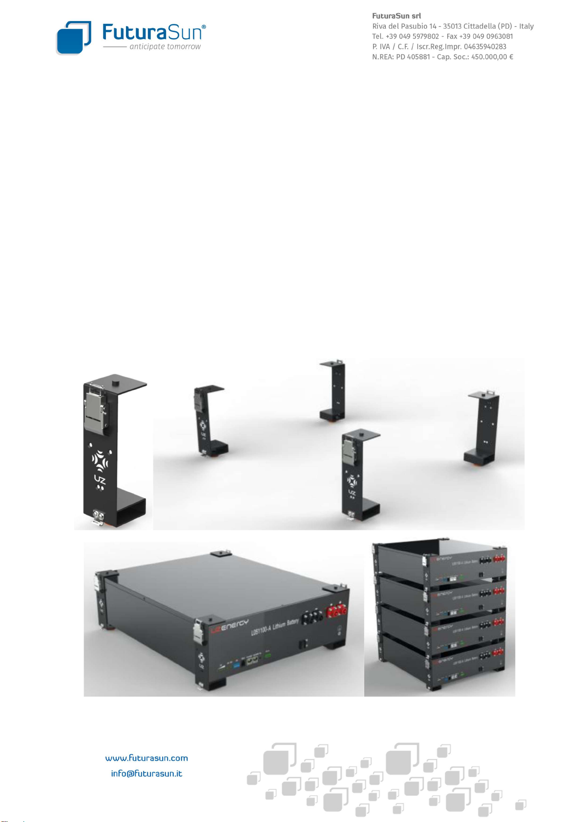
UZ PowerLite L051100-A and L051100-A1 batteries are modules with a capacity of 5.12 kWh and the integrated controller
allows the management of several modules connected in parallel. This manual provides information on how to use the
batteries and on the safety precautions to prevent possible accidents. Therefore, please read this manual carefully and
keep it handy in case of need.
SAFETY PRECAUTIONS
The batteries are designed with extremely high safety standards. Nevertheless, any electrical equipment can be dangerous
if used improperly and, therefore, be the source of possible electric shocks and fires that can cause serious injury, and/or
even death. The following precautions should be followed to the letter.
Failure to comply with the following instructions can result in electric shocks and fires that can cause serious injury,
and/or even death
To connect the batteries, only use the cables supplied.
Do not tamper with the cables. Any damage to the cables may result in electric shock or fire.
Therefore:
1. Do not modify or damage cables
2. Do not place heavy objects on top of the cables and do not subject the cables to traction
3. Do not place the cables near heat sources that can overheat them
5. To disconnect a power or communication cable, pull the plug rather than the cable.
Be very careful when connecting the power and communication cables:
1. If a power cable is connected incorrectly, the contact resistance can cause damage to the batteries and/or lead to
overheating and even fire.
2. Fully insert the cable connectors.
It is forbidden to install the batteries in poorly ventilated rooms, where heat can build up inside the modules and cause a
fire
It is forbidden to install the batteries exposed to sunlight or near heat sources, to avoid thermal deformation, failure or
fire. Take care when installing near windows.
It is forbidden to install the batteries in environments where smoke, steam, high humidity or excessive dust may be
present.
All personal protective equipment (insulating gloves, goggles, etc.) must be worn during installation
It is also mandatory:
1. To prevent water and/or foreign bodies to enter the batteries
2. Water and/or foreign bodies inside the modules can result in electric shock and/or cause fires
3. Should the above two situations occur, immediately switch off the batteries and disconnect all cables.
It is forbidden to open, dismantle or modify the batteries, as this could cause electric shock or fire.
It is forbidden to cover the ventilation openings of the battery modules, to avoid internal overheating or possible fires.
Therefore:
1. Do not install the batteries in poorly ventilated rooms.
2. Remove any dust build-ups from the ventilation openings.
3. Do not install the batteries upside down or on their sides.
4. Do not place the batteries on top of carpets or beds.
5. Do not obstruct the ventilation openings.
Install the batteries in a stable position
1. An unstable installation can cause the batteries to fall, which could result in damage to the batteries and injury to the
users

- 6 -
2. Do not install the batteries upside down or on their side as they could fall, which could result in damage to the batteries
and injury to the users
To avoid damage to the batteries during transport and/or handling, leave them in their original packaging until installation.
Make sure that the mechanical installation follows the instructions in this manual in order to avoid damage or injury. In
case of rack installation, securely fasten the rack to the floor. An entire rack falling could be a dangerous cause of property
damage, personal injury and/or even death.
Do not touch the batteries with wet hands to avoid possible electric shocks.
All wiring must be protected and must not cause mechanical obstacles to people/animals that may transit nearby, becoming
a source of possible fall and/or injury.
If a battery is faulty, switch it off immediately and disconnect all its wiring.
Leaning on, sitting on or stepping on batteries is prohibited, as it could cause personal injury and damage the batteries. It
is also forbidden to place any object on top of the batteries.
When disposing of the batteries and the end of their life, make sure to comply with the regulations of the country of
installation. The product cannot be disposed of as household waste.
In the event of liquid leaking from the batteries, observe the following safety measures:
Do not allow the liquid to come into contact with skin or clothing.
In case of contact with skin or clothing, rinse immediately with plenty of water.
If the liquid comes into contact with the eyes or enters the mouth, rinse immediately with plenty of water and
immediately seek medical attention.
Lastly, contact the support service
PRECAUTIONS FOR USE
Should one of the following situations occur, switch off the batteries and contact customer service.
1. Presence of smoke, strange smell or noise from the batteries
2. Presence of water or foreign objects inside the batteries.
3. Battery falling or damaged casing.
The following is forbidden:
- Removing the batteries.
- Making changes to the product.
- Abnormal charge / discharge, heat generation, gas eruption, or fire.
- Touching the terminals when the batteries are in operation.
- Throwing the product into the fire or expose it to heat and open flames.
- Wetting or immersing the product in any liquid.
- Subjecting the batteries to mechanical stress, shocks and falls.
- Using the batteries for medical purposes.
- Connecting any device that exceeds the operating voltage and current of the batteries
- Disconnecting the cables during battery operation.
- Drilling into the batteries in any way.

- 7 -
PRODUCT SPECIFICATIONS
Battery model L051100-A L051100-A1
Technology Lithium Iron Phosphate - LiFePO4 (LFP)
Capacity 100 Ah
Rated voltage 51.2 V (3.2 V single cell)
Operating voltage range 44.8 V-57.6 V
Rated energy 5,12 kWh
Discharge depth 100 %
Maximum charge/discharge power 2,56 kW / 5,12 kW
Short circuit current 210 A
Operating SOC interval 0 % – 100 %
SOC being transported 50 %
Operating temperature range Charge: 0 °C to 50 °C | Discharge: -20 °C to 55 °C
Temperature range for storage -20 °C to 50 °C
Relative humidity range (RH) 20 % - 80 %
Rated charging current 50 A (0,5 C)
Maximum charge current 50 A (0,5 C)
Rated discharge current 50 A (0,5 C)
Maximum discharge current 50 A (0,5 C)
Rated DC power 2.56 kW
Insulation resistance >100 M
Self-discharge ≤5% (25 °C, 50% SOC) per month
Voltage difference among cells V ≤20 mV
IP degree of protection IP20
Recommended use Internal installation
Weight 45 kg
Dimensions L x W x H - 440 mm x 530 mm x 132 mm
Communication CAN / RS845 / Dry contact
Expected life 10 years

- 8 -
L051100-A - FRONT VIEW
REF. NAME MODEL NOTES
1 4 SOC LED
2 ALARM LED
3 OPERATION LED
4 DIALER
5 COMMUNICATION PORT RJ11 RS 232 for communication with PC
6 COMMUNICATION PORT x 2 RJ45 CAN for inverter, RS485 for internal communication
1 RESET
2 DRY CONTACT
3 ON/OFF SWITCH
4 NEGATIVE INPUTS PSR6XAB Black 25 mm2
5 POSITIVE INPUTS PSR6XBB Orange 25 mm2
6 EARTH M6 Yellow Green
L051100-A
CONNECTOR BATTERY SOCKET BATTERY PLUG SPECIFICATION NOTES
POSITIVE 1 PSR6XBB PSR6XB25 ORANGE 5.7 mm 25mm2 IP67
POSITIVE 2 PSR6XBB PSR6XB25 ORANGE 5.7 mm 25mm2 IP67
NEGATIVE 1 PSR6XAB PSR6XA25 ORANGE 5.7 mm 25mm2 IP67
NEGATIVE 2 PSR6XAB PSR6XA25 ORANGE 5.7 mm 25mm
2
IP67
X2 COMMUNICATION
PORT
RJ 45
PIN 1: CAN-H
PIN 2: RS485-A
PIN 3: RS485-B
PIN 4: NC
PIN 5: CAN-L
PIN 6: RS485-B
PIN 7: RS485-A
PIN 8: GND
CAN / RS845
PC COMMUNICATION
PORT
RJ 11
PIN 1: NC
PIN 2: NC
PIN 3: BMS TX –
PC RX
PIN 4: BMS RX –
PC TX
PIN 5: GND
PIN 6: NC

- 9 -
L051100-A1 - FRONT VIEW
REF. NAME MODEL NOTES
1 4 SOC LED
2 ALARM LED
3 OPERATION LED
4 DIALER
5 COMMUNICATION PORT RJ45 CAN for inverter, RS485 for internal communication
6 COMMUNICATION PORT x 2 RJ45 RS485 for internal communication
7 RESET
8 DRY CONTACT
9 ON/OFF SWITCH
10 NEGATIVE INPUTS PSR6XAB Black 25 mm2
11 POSITIVE INPUTS PSR6XBB Orange 25 mm2
12 WI-FI
13 EARTH M6 Yellow Green
L051100-A1
CONNECTOR BATTERY SOCKET BATTERY PLUG SPECIFICATION NOTES
POSITIVE 1 PSR6XBB PSR6XB25 ORANGE 5.7 mm 25mm2 IP67
POSITIVE 2 PSR6XBB PSR6XB25 ORANGE 5.7 mm 25mm
2
IP67
NEGATIVE 1 PSR6XAB PSR6XA25 ORANGE 5.7 mm 25mm
2
IP67
NEGATIVE 2 PSR6XAB PSR6XA25 ORANGE 5.7 mm 25mm
2
IP67
X1 COMMUNICATION
PORT
RJ 45
PIN 1: CAN-H
PIN 2: RS485-A
PIN 3: RS485-B
PIN 4: NC
PIN 5: CAN-L
PIN 6: RS485-B
PIN 7: RS485-A
PIN 8: GND
CAN / RS845
X2 COMMUNICATION
PORT
RJ 45
PIN 1: NC
PIN 2: RS485-A
PIN 3: RS485-B
PIN 4: NC
PIN 5: NC
PIN 6: RS485-B
PIN 7: RS485-A
PIN 8: GND
RS485
WI-FI SOCKET MAGPIE WI-FI STICK V190603-T ON REQUEST

- 10 -
INSTALLATION
Power Lite batteries can be installed horizontally or fixed to the wall using the appropriate mounting accessories. In both
cases, the floor or wall must be able to support the full weight of all batteries and other equipment present. For fixing, only
use the original accessories supplied. For the installation instructions for these systems, please refer to the relevant
installation manuals.
The batteries are capable of charging and discharging within the temperature ranges indicated in this manual. When
approaching the limits of the above-mentioned ranges, the batteries can limit the charging or discharging power to
safeguard battery life. Therefore, the batteries should not be operated at temperatures that are too low or too high, such
as in poorly ventilated rooms or exposed to the sun.
The average room temperature should always be between 0 °C and 30 °C
Coils require adequate installation space for wiring and to ensure proper air supply for cooling ventilation. Do not place any
objects in the required free space around the batteries. Do not install any objects on top of the batteries that could restrict
access to the batteries or that could fall on them and damage them. Do not install the batteries upside down
HORIZONTAL INSTALLATION - H100
This type of installation is the most common and requires the H100 accessory. With this system, it is strongly recommended
not to install more than 4 batteries stacked.

- 11 -
The batteries require the following free space for ventilation and maintenance
The maximum permissible inclination is as follows:
- +/- 2 degrees from right to left side
- +/- 5 degrees from front to rear
FLOOR INSTALLATION - C100

- 12 -
The batteries require the following free space for ventilation and maintenance
The maximum permissible inclination is as follows:
- +/- 2 degrees from right to left side
- +/- 5 degrees from front to rear

- 13 -
FLOOR INSTALLATION - C300
The batteries require the following free space for ventilation and maintenance
The maximum permissible inclination is as follows:
- +/- 2 degrees from right to left side
- +/- 5 degrees from front to rear

- 14 -
WIRING
Depending on the type of installation selected, it will be necessary to use the appropriate connection cables, which are not
supplied with the individual battery module package
ARTICLE SPECIFICATIONS QUANTITY IMAGE NOTES
CA 01
CABLE KIT
PARALLEL
Negative and
positive power
cables
Length: 18.5 cm
Cross-section 25
mm2
2
For rack
mounting or
with H100
Black
communication
cable between the
batteries
Length: 18.5 cm
RJ45 double plug
1

- 15 -
ARTICLE SPECIFICATIONS QUANTITY IMAGE NOTES
CA 05
CABLE KIT
PARALLEL
Negative and
positive power
cables
Length: 60 cm
Cross-section 25
mm2
2
For installation
with
C100
and
C300
Black
communication
cable between the
batteries
Length: 80 cm
RJ45 double plug
1
CA 03
CABLE KIT
FOR
CONNECTION
TO THE
INVERTER
Negative and
positive power
cables
Length: 150 cm
Cross-section 25
mm2
2
Black
communication
cable between the
batteries
Length: 150 cm
RJ45 double plug
1
Yellow-green earth
cable with double
M6 eyelet
1

- 16 -
WIRING POWER LITE L051100-A
SINGLE BATTERY WIRING
MULTI-BATTERY WIRING FOR INVERTERS UP TO 100 A

- 17 -
MULTI-BATTERY WIRING FOR INVERTERS ABOVE 100 A
MULTI-BATTERY WIRING - COMMUNICATION CABLES (PCS = OPTOR HYBRID INVERTER)

- 18 -
DIP SWITCH SETTINGS POWER LITE L051100-A

- 19 -
WIRING POWER LITE L051100-A1
MULTI-BATTERY WIRING FOR INVERTERS UP TO 100 A

- 20 -
MULTI-BATTERY WIRING FOR INVERTERS ABOVE 100 A
MULTI-BATTERY WIRING - COMMUNICATION CABLES (PCS = OPTOR HYBRID INVERTER)
This manual suits for next models
1
Table of contents
Popular Batteries Pack manuals by other brands

Inventus Power
Inventus Power PROTRXion S-48V60-TRX-HD quick start guide

Rebelcell
Rebelcell Start user manual

PORODO
PORODO PD-PBFCH027 user manual

Black & Decker
Black & Decker LBX36 instruction manual

UPOWER Ecoline
UPOWER Ecoline UE48LI100-3U user manual

Parkside
Parkside 326390-1904 operating instructions