K-9 K9-5 Classic User manual

COPYRIGHT:OMEGARESEARCH&DEVELOPMENT,INC.2000
MODEL: K9-5
Classic
Page - 36
Programming Transmitters
Each system includes two pre-programmed transmitters. To program transmitters, such
as when adding a transmitter or changing the button assignment, follow this process:
Step 1- Turn "on" the ignition.
Step 2- Within 5 seconds of turning "on" the ignition, press the Valet Switch 5 times. The
sirenwill chirp,confirming thatfor thenext 10seconds thesystem isready tolearn
a transmitter code. When the first transmitter code is learned all existing stored
codes will be erased. To enter a transmitter code, simply press and release the
transmitter button which is desired to arm and disarm the system*.
Step 3- Repeat this procedure for each transmitter desired to operate the security system.
The system will chirp the siren once to confirm that each transmitter code was
learned. Bothoftheothertwo transmitter button's functions will automaticallybe
learned when the arm / disarm button is learned. If a code is not received within
a 10 second period, the learning process will automatically terminate.
* Other button operations may be used, as shown in this chart:
Arm / Disarm Trunk Release 3rd Channel
Large Center Button Small Right Button Small Left Button
Small Right Button Large Center Button Small Left Button
Small Left Button Large Center Button Small Right Button
Feature#22configuresarmand disarm to separate buttons;pleaseseetheOwner's Manual.
MI_K9-5CLASSIC_REV1
INSTALLATION MANUAL

Page - 2
Contents
Wiring Overview ....................................................................................................................... 18-19
Black Wire (Negative Ground) ..................................................................................................... 3-4
Red Wire (Constant Power) .......................................................................................................... 4-5
Yellow Wire (Ignition Power) ......................................................................................................... 5
Orange Wire (Starter Interrupt Output)........................................................................................ 5-7
Gray Wire (2nd Channel/Trunk Release Output) ............................................................................ 8
Brown Wire (Positive Siren Output) ........................................................................................... 9-10
White Wire (Positive Flashing Parking Light Output)............................................................. 11-13
Green Wire (Negative Door Trigger)........................................................................................ 13-15
Violet Wire (Positive Door Trigger).............................................................................................. 16
Blue Wire (Negative Instant Trigger) ................................................................................... 17 & 20
Pink Wire (3rd Channel Output) ............................................................................................. 20-21
White/Black Wire (Domelight Supervision Output) ...................................................................... 21
LED/Valet Switch Combination Assembly ................................................................................... 22
Optional Customized LED & Valet Switch Mounting ............................................................. 22-23
Dual Zone Port For Optional Sensor........................................................................................ 23-24
Optional Backup Battery Port ....................................................................................................... 24
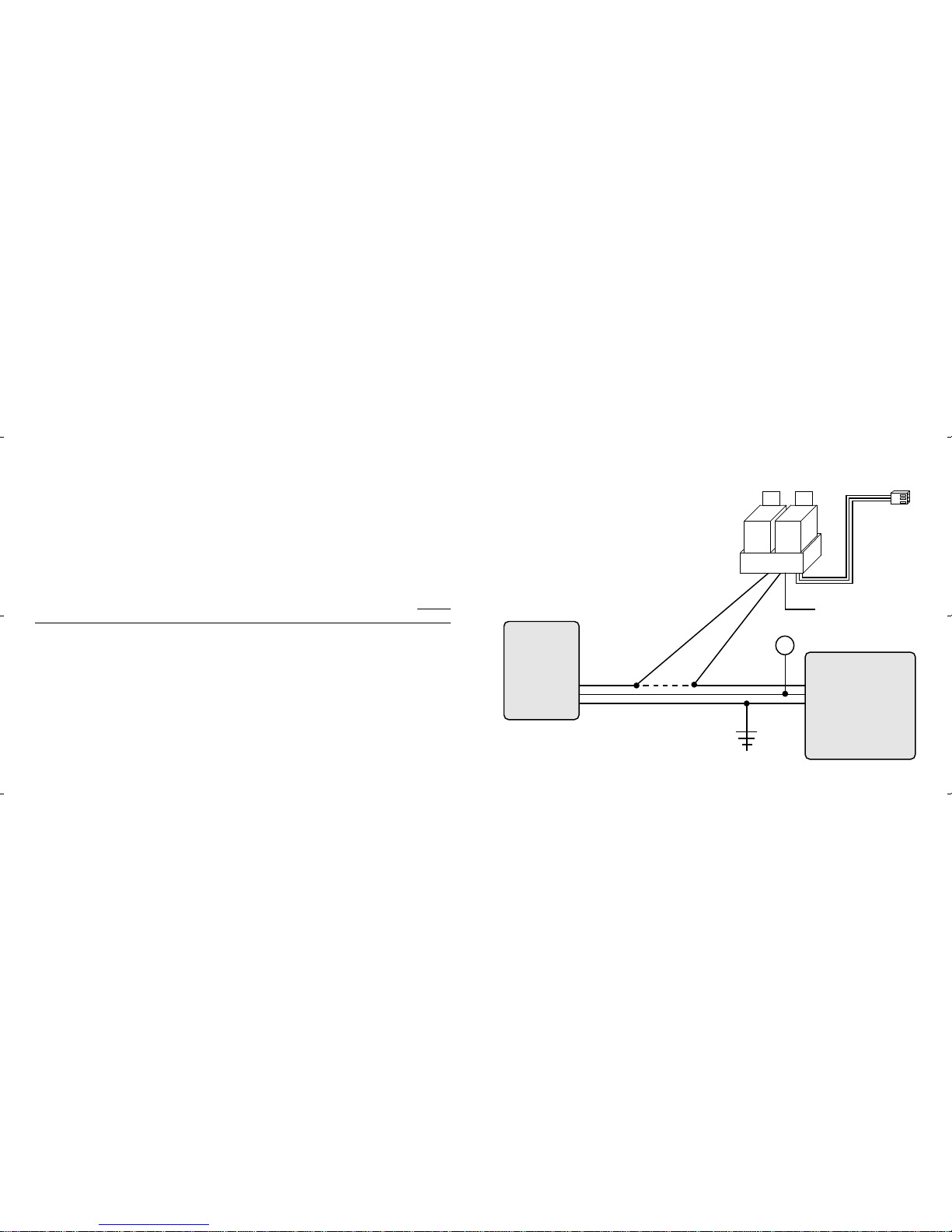
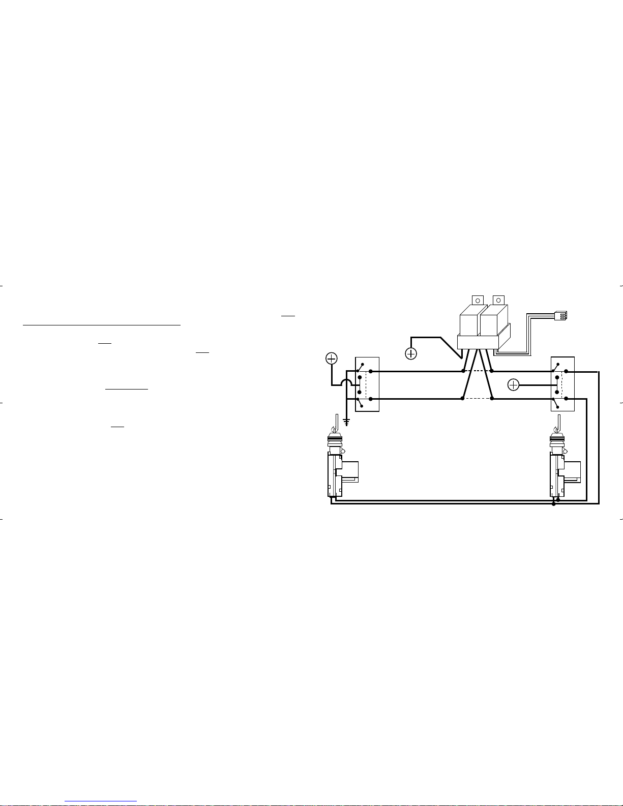
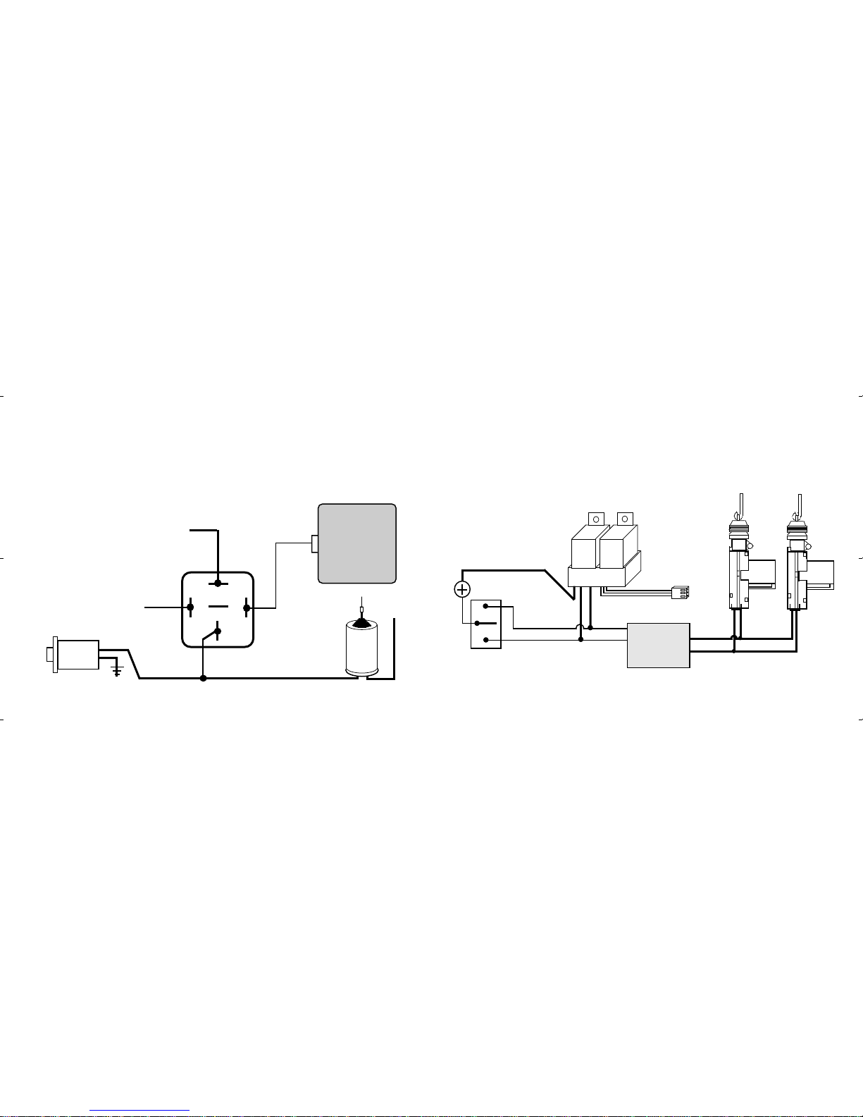
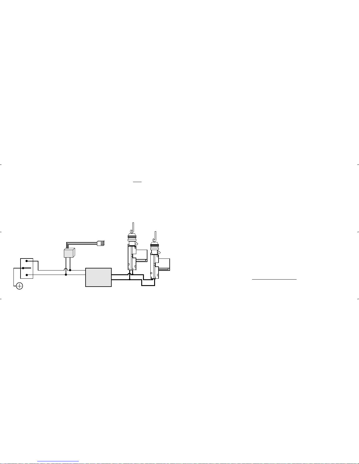
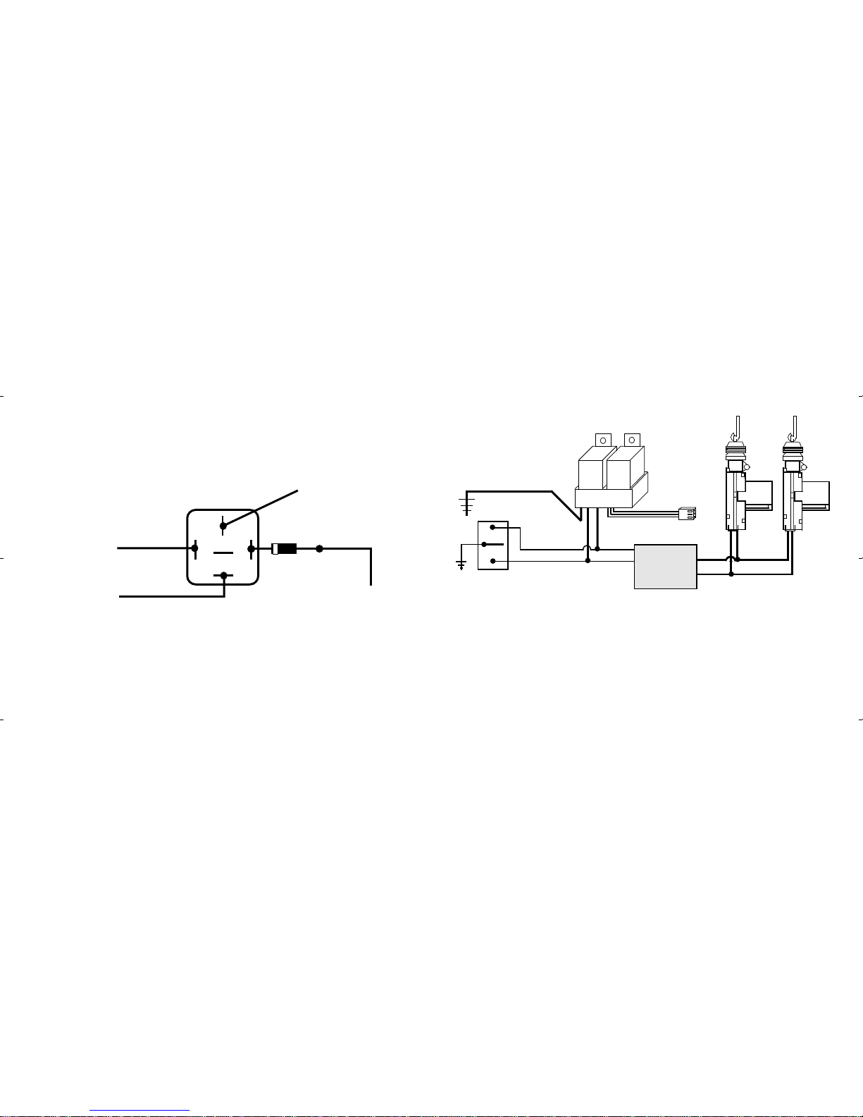
Power Doorlock Interface Port.................................................................................................. 25-33
Programmable Features ............................................................................................................. 34-35
Programming Transmitters ............................................................................................................. 36
Page - 35
1) Ignition-Activated Anti-Carjacking Protection: Default OFF.
2) Door-Activated Anti-Carjacking: Default OFF.
3) Last Door Arming: Default ON.
4) Doors Lock With Last Door Arming: Default ON.
5) Current Sensing: Default ON.
6) Doors Lock At Ignition "On": Default ON.
7) Unlock Output #1 At Ignition "Off": Default ON.
8) Not used in this model
9) Open Door Bypass To Features #6, #7: Default ON.
10) Lights On 5 / 30 Seconds Upon Disarm: Default 30 Seconds (= center button).
11) Automatic Rearming: Default ON.
12) 2nd Channel Output Disarms System: Default ON.
13) .8 / 3 Second Doorlock Pulse: Default .8 Second (= center button).
14) Double Unlock Pulse: Default OFF.
15) 3 / 45 Second Arming Delay: Default 3 Seconds (= center button).
16) Confirmation Chirp: Default ON.
17) 30 / 60 Second Activated Alarm Cycle: Default 60 Seconds (= center button).
18) Pulsed Horn / Steady Siren Output: Default Steady Siren (= center button).
19) Loud / Soft Pulsed Horn Chirps: Default Loud.
20) Total Closure Lock Output: Default OFF.
21) Remote-Activated Anti-Carjacking Protection: Default OFF.
22) One / Two Button Arming / Disarming: Default One Button (= center button).

Installation Considerations
Mounting The Main Control Module: The Main Control Module contains the elec-
tronics necessary for the security system's operation. Always mount this module in the
vehicle's interior compartment, in a secure location that is not easily accessible. Ensure
that moisture, vibration and temperature extremes are minimized. Acceptable locations
may include mounting behind the dash, behind the glovebox or other interior panels.
Mounting The Siren: Find a location in the engine compartment away from the ex-
treme heat of the engine and manifold. A suitable location will offer a firm mounting
surface, will also allow sound dispersion out of the engine compartment, and not be acces-
sible to a thief. The siren must be pointed downward to avoid moisture collecting inside it
and to enhance sound dispersal.
Wiring Connections: The security system's wires should be securely connected to the
appropriate vehicle wires with the proper terminals, connectors, or by soldering and
insulating with quality vinyl electrical tape or heat shrink tubing. All wiring should be
carefully routed to avoid the possibility of chaffing or otherwise being damaged. Make all
required connections, then plug the harnesses into the control module.
Page - 3
Negative
Ground
Black Wire
The Black wire is the source of Negative ground which is necessary for the security
system to operate. The proper connection of the Black grounding wire is vital.
Page - 34
Programming Features
Thissystemhas22programmablefeaturesthatcanbeprogrammedusingthevaletswitch
and transmitter. See the Owner's Manual for further Programmable Features information;
brief manual programming instructions are:
Step 1- Turn "off" the ignition.
Step 2- Within 5 seconds of turning "off" the ignition, press the Valet Switch 5 times. The
siren will chirp, followed by a short siren burst, confirming that for the next 10
seconds the system is ready to receive a feature number.
Step 3- Press the Valet Switch the number of times that is equal to the feature number.
Example: Press the Valet Switch six times if Feature #6 is to be changed.
Step 4- The siren will respond by chirping the same amount as the feature number.
Example: The siren responds with six chirps.
Step 5- Press the largetransmitterbuttontoturn the feature "on". Whendone,thesirenwill
respond with one chirp.
Step 6- Pressthesmall lefttransmitter buttontoturnthefeature"off".Whendone,the siren
will respond with two chirps.
Step 7- For each additional feature to be programmed, repeat steps 3-6.
If the Valet Switch is not pressed, or if a transmitter signal is not received within a 10
second period, the Programmable Features learning process will automatically terminate.

CONNECTION:Usingthecorrectsized crimp-on ringterminal,connectthe Black wire
to the metal frame of the vehicle, preferably using an existing machine-threaded fastener.
Make sure that the ring terminal attached to the Black wire has contact with bright, clean
metal. If necessary, scrape any paint, rust or grease away from the connection point until
the metal is bright and clean. If the control module has an insufficient ground connection,
the security system can find partial ground through the wires that are connected to other
circuits, but the alarm will not function correctly, giving the impression of a defective
control module. The alarm can partially work, so a bad ground wire connection would
be suspected. In some cases the alarm could arm and disarm properly but not function
correctly otherwise. When power and ground are first applied the alarm will trigger
instantly. The Black wire attached to the control module is the antenna wire. Do not
connectthiswiretoanything or thetransmitter'srangewillbereducedor eliminated.
Stretch the Black antenna wire out and as high as possible for the best operating range.
Page - 4
The Red wire's function is to supply Constant Positive 12 Volts for security system's
operation. When 12 Volts is first applied to the Red wire, the system will revert to state in
which it was in when power was taken away. If the vehicle to be serviced, especially if it
involves the battery, the system should be placed in Valet Mode. This will prevent the
system from being activated if the battery is disconnected and reconnected. The Red wire
also supplies 12 Volt Positive to the module's internal relay for flashing the parking lights.
Constant Power
Red Wire Cut
+
12
Volts
Green
wire
White
wire
Pneumatic
Actuator
with built-in
electrical
switch
Black Wire (if present)
to Ground
Relay Relay
DLS-V
pump. The switches are operated when the doors are
locked or unlocked by the inside doorlock knob or
the key in the exterior doorlock cylinders. The
polarity supplied by the switch determines if
the pump sends vacuum or pressure through
hoses to the actuator. Since the pump must
operate for about 3 seconds, the doorlock
pulse must be changed (Programmable
Feature #13).
Theconnectionpointmaybe in either kickpanel
or at the supply pump itself, which is located in
the trunk or under the rear seat.
DLS-V connector
plugs into
Control Unit
Page - 33
To
Ground
Pneumatic Pump-
supplies vacuum
or pressure which
operate Actuators
to lock & unlock
doors & trunk

CONNECTION: Connect the Red wire to a Constant Positive 12 Volt source. This
source should have Positive 12 Volts with at least a 15 Amp capacity at all times and in all
ignitionkey positions. Connectionlocationscanbeatthesupplywireattheignitionswitch,
the supply wire behind the fuse block or the fuse/junction block. Never just insert the Red
wire or any other security system wire behind a fuse. Also, please note that connecting
directly to the battery's Positive terminal will expose this connection to failure due to a
corrosive environment unless the connection has a protective coating.
Page - 5
The Orange wire is for an optional starter disable socket and relay. The function of this
wire is to provide a Constant 500ma Ground Output whenever the security system is in an
Starter Interrupt Output
Orange Wire
TheYellowwireisanignition"on"inputtothesecuritysystem. Thisconnectioniscritical
to the proper operation of many of the security system's features.
CONNECTION: This wire supplies Positive 12 Volts to the control module whenever
the ignition switch is "on". This connection should be made at the ignition switch harness,
to the primary ignition circuit. Primary ignition has 0 Volts when the ignition key is in the
"Lock", "Off" and "Accessory" positions; and Positive 12 Volts in the "Run" and "Start"
positions. Locate the correct wire at the ignition switch harness and securely splice the
Yellow wire to it.
Ignition Power
Yellow Wire
Some vehicles have a type of power doorlock system in which mechanically locking and
unlocking the driver's door will operate an electrical switch in the door which supplies
voltagetoactuatorsintheotherdoors.Thereisnoactuatorinthedriver'sdoor,onlyaswitch.
An indication of this type
of power doorlock system
is when the driver door
key will operate the pass-
enger door, but the pass-
enger side will not oper-
ate the driver door.
Adding the optional DS-2 Actuator and the DLS and 2 Relays
DLS
Relay Relay +
DLS Blue wire to DS-2 Red wire
DLS Green wire to DS-2 Blue wire
Note: Use this
diagram when
adding actuators
to a vehicle not
equipped with
factory power
door locks.
DLS Brown and
White wires
connect to
Ground
DLS Violet
wire to
12 Volt
DLS connector
plugs into
Control Unit
Vacuum Doorlocks and the optional DLS-V and 2 Relays
This doorlock system is used on older Mercedes Benz vehicles and consists of electrical
switches (built into pneumatic actuators) which supply 12 volts or ground to a pneumatic
Page - 32

Page - 6
armedstate. Thisoutputsupplies Negative Groundtooneside of therelay'scoil. Theother
sideoftherelaycoilwillbesuppliedwithPositiveVoltagefromtheignitionswitch,butonly
if the ignition switch is turned to the "start" position. If this occurs, the coil will energize,
activatingtherelay,whichin turnwillopenthestarter circuit. Thestarterinterruptprevents
the vehicle from starting only if the alarm is armed (including while the alarm is activated),
and will draw current from the vehicle's electrical system only if an attempt is made to start
the vehicle.
CONNECTION:Tointerruptthevehicle'sstartercircuit,thestarter wiremustbelocated
and cut. It is recommended that this connection be done as close to the ignition switch as
possible. Use a voltmeter, not a test light, to find the correct wire, which is the wire from
theignitionswitchtothestarter solenoid. CAUTION! Avoid theairbagcircuit! Improper
useofatestlightcancausedeploymentoftheairbag,whichmayresultinbodilyinjury! Test
lights can also damage on-board computers and associated sensors. The starter wire
will read Positive 12 Volts only when ignition key is in "start" position (cranking the
engine). Cut this wire at a suitable location. Confirm that this is the correct wire by
turning the ignition switch to the "start" position. The starter should not engage.
Connect the optional starter disable socket's Red wire to the ignition switch side, and its
White wire to the starter solenoid side. Be sure that good, solid electrical connections are
made as this generally is a high amperage circuit. Connect the security system's Orange
wire to the Orange wire of the starter disable socket. Note: If the Orange wire touches 12
volts positive directly or has more than a 500ma ground load, the circuit will be damaged.
Lock
Unlock Unlock
DLS
Lock
Driver
Doorlock
Actuator
Relay Relay
++
Passenger
Doorlock
Actuator
Ground
DLS Violet
Wire to
12 Volt
Constant
DLS connector
plugs into Control
Unit
Driver
Doorlock
Switch
("Primary")
Passenger
Doorlock
Switch
("Secondary")
When testing the wires for the "switch" and the
"motor" sides, both should be cut. Otherwise, false
voltage reading can occur. Verification of "Primary"
and "Secondary" status must be made; in some cases
the"Primary"switchisthePassengerDoorlockSwitch.
5 Wire Reversal Rest At Ground doorlocks
with the optional DLS and 2 SPDT Relays
wire, motor" side
DLS Blue wire to "unlock
wire, motor" side
DLS White wire to
"lock wire, switch" side DLS Green wire to "lock
Cut both
"lock" and
"unlock"
wires
in car
12 Volt
Constant
DLS Brown wire to
"unlock wire, switch" side
Page - 31

Configuring a Starter Disable using the AU-SOCKET and one SPDT Relay.
Page - 7
Ignition
Switch
Control
Unit
Starter
Solenoid
30
86 87a 85
87
Control
Module
Orange wire
Socket
Orange wire
Starter disable socket's
Red wire to the ignition
switch side of the cut.
Starter disable socket
White wire to the starter
solenoid side of the cut.
Cutting the vehicle's
starter wire will leave
two sides- the "ignition
switch side" and the
"starter solenoid side".
5 Wire Reversal Rest At Ground Systems: Thispowerdoorlocksystem
differs from the negative and positive pulse systems in the fact that there are no relays or
doorlock control unit. In this type of system, the switches themselves supply the positive
voltagedirectlyto thedoorlockactuators,and, moreimportantly,provide thereturnground
path. Thecorrect doorlockinterfaceforthistypeofsystemistheoptionalDLSand2 relays.
Theimportantthingtorememberisthewiresinthissystemrestatground,whichmeansthat
the wires must be "opened", or cut, to make the connections.
Examinethewires ontheback oftheswitch. Normallyfive wireswillbe found. Ofthese
wires, one will be constant 12 volts positive, regardless of the switch's position. Two wires
will be grounded regardless of the switch's position. Of the two remaining wires, one will
show12voltspositive when the switchispushedto "lock", and theotherwillshow12 volts
positive when the switch is pushed to "unlock".
Thesetwowiresarebothroutedto the doorlock actuators and are connected toeitherend
of the actuator's motor winding. When the switch is pushed to one position, one of these
two wires will have 12 volts. This voltage flows through the wire to the actuator's motor
winding,andsincetheother wire is stillresting at ground anelectricalcircuitis completed.
When the switch is pushed to the opposite position the electrical flow is reversed. When
the correct wires are found, they must be cut. Notice in the diagram (following page) that
thedriver's switchis theprimary switchand referredto asthe "switch"wires. The wiresthat
gotothe secondaryswitchare referredtoas the"motor"wires. Even thoughthecutis made
between the switches, the two sides are still correctly called the "switch" and the "motor"
sides, with consideration of "Primary" and "Secondary" switch; please see the diagram.
Page - 30

Wiring an optional Relay for Trunk Release.
2nd Channel / Trunk Release Output
Gray Wire
The function of the Gray wire is to provide an optional output, the primary use being
trunk release. Press and hold the transmitter's small right button for two seconds to acti-
vate this output. When activated the Gray wire will provide a 250mA Negative Ground
pulse for 1 second; or, stay grounded for as long as the small right transmitter button is
depressed, for up to 15 seconds. The siren will chirp twice for a confirmation and the
doors will also unlock.
Page - 8
Release
Switch
Release
Solenoid
To 12 Volt
Positive
Optional
Relay
87
30
86 87a 85
Control
Unit
Gray wire
To 12 Volt
Positive
ToPositiveorNegativeasneeded.Inthis
case,Negativeisrequired; inothercases,
Positive. In some applications the wire
willrestatGround.Cutthewire;"switch"
side to Pin 87a, "solenoid" side to Pin 30
and 12 Volts to Pin 87.
ModelDLS-TheDLSisadualrelaysocketwitha harness and connector to plug into the
alarmcontrolmoduleandnon-terminatedwirestospliceintothevehicle's wiring.TheDLS
and two relays are the most universal doorlock interface available. The relays used with it
are standard 30 amp single pole, double throw (SPDT) automotive relays.
-29
Relay
DLS
Relay +
DLS Violet wire to 12 Volt
Lock
Unlock
DLS Green wire
to "Lock" wire DLS Blue wire to
"Unlock" wire
+
Doorlock
Switch Vehicle's Doorlock
Relay Control Unit
To Constant
12 Volts
DLS Brown & White wires
are not used in this application
DLP-P3
connector
plugs into
Control Unit
3 Wire Positive doorlocks with the optional DLS
and 2 SPDT Relays
Page - 29

Page - 9
Positive Siren Output
Brown Wire
HORN CONNECTION: The Brown wire may be connected to the vehicle's existing
horn wire, but a relay and diode must be used to switch the polarity to Negative. The horn
switch wire is typically found at the steering column. Use a digital multimeter (DMM) to
identifythehornwire. CAUTION! Avoidthe Airbagcircuit! Thecorrect wirewillshow
Positive 12 Volts normally, and no voltage when the horn is honked. Direct connection of
the Brown wire to the horn itself is not recommended because the average horn requires
The Brown wire is a 1 Amp Positive output designed to operate the electronic siren for
audible confirmations, and also to sound if the alarm is triggered. An alternative to the
siren is to program the alarm to pulse this output to sound the vehicle's horn by adding a
relay and diode. This would require changing Programmable Feature #18 from the preset
steady output to a pulsed output.
SIREN CONNECTION: The Brown wire may be connected directly to the siren's Red
wire, and the siren's Black wire is connected to (-) Ground.
Mounting The Siren: Find a location in the engine compartment away from the extreme
heatofthe engineandmanifold. Asuitable locationwilloffer afirmmountingsurface, will
alsoallowsounddispersionoutoftheenginecompartment,andnot be accessible to a thief.
The siren must be pointed downward to avoid moisture collecting inside it and to enhance
sound dispersal.
pushed to "unlock". Since the security system's output polarity must be reversed from
negative ground to 12 volts positive, an optional doorlock interface must be used. Three
interfaces are available - the models DLP-P3, or the DLS with optional SPDT relays.
Model DLP-P3 - Three pin connector with a transistor converter network which changes
the security system's negative pulse doorlock outputs to positive pulses. Allows direct
connection of the security system's outputs directly to a vehicle with positive pulse
doorlocks. Overall length 20". Easier and more efficient than using relays for vehicles that
have positive pulse doorlock systems.
+
+
Doorlock
Actuators
DLP-P3 Blue wire
to "Unlock wire
DLP-P3 Green wire
to "Lock" wire
DLP-P3
connector
plugs into
Control Unit
Lock
Unlock
Vehicle's Doorlock
Relay Control Unit
Doorlock
Switch
3 Wire Positive doorlocks with the
optional DLP-P3
To Constant
12 Volt Page - 28

more than the 1 amp output that the Brown wire supplies. One alternative is to disconnect
the horns, then operate the horn switch. A clicking sound from the vehicle will confirm the
presence of a horn relay. Another alternative is to check a wiring schematic of the vehicle
in question.
Configuring An Optional Relay: The Brown Siren / Horn output wire has a 1 Amp
capacity, which, if exceeded, can damage the security system control module. In certain
situations, among them multiple optional sirens or utilizing the vehicle's horn, an optional
SPDT relay is required. When adding a relay, a protection circuit in the form of a 1 Amp
diode on the Brown Siren / Horn output wire is recommended.
Page - 10
Optional Relay Wiring Diagram
30
86 87a 85
87
(-) Ground
(+) or (-) as
needed to operate
the horn / sirens
To vehicle's
horn wire.
Brown wire
from module
1 Amp
diode
Relay
DLS
Ground
Relay
DLS Violet wire to Ground
Lock
Unlock
DLS Green wire
to "Lock" wire DLS Blue wire to
"Unlock" wire
++
Doorlock
Actuators
Vehicle's Doorlock
Relay Control Unit
Doorlock
Switch
3 Wire Negative doorlocks using the optional
DLS and 2 SPDT Relays
3 Wire Positive Pulse Systems:This power doorlock system is very similar
to the three wire negative pulse system except the vehicle's doorlock switches use 12 volt
positive pulses to operate the vehicle's doorlock relays or control unit. Examine the wires
onthebackoftheswitch.Ofthethreewires,onewillbeconstant12 voltpositive,regardless
of the switch's position. Of the two remaining wires, one will show 12 volt positive when
the switch is pushed to "lock", and the other will show 12 volt positive when the switch is
DLS connector
plugs into Control
Module
Page - 27

Page - 11
123456
123456
123456
123456
123456
123456
123456
123456
123456
123456
12345
12345
12345
12345
12345
12345
12345
12345
12345
12345
123456
123456
123456
123456
123456
123456
123456
123456
123456
123456
123456
123456
123456
123456
123456
123456
123456
123456
123456
123456
123456
123456
123456
123456
123456
123456
1234
1
23
4
1
23
4
1
23
4
1
23
4
1
23
4
1
23
4
1
23
4
1
23
4
1
23
4
1234
12345678
1
234567
8
1
234567
8
1
234567
8
1
234567
8
1
234567
8
1
234567
8
1
234567
8
1
234567
8
1
234567
8
1
234567
8
1
234567
8
1
234567
8
12345678
12
12
12
12
10 Amp
White
wire
Rear Body Harness
Head
Light
Switch
Junction
Block
Dash Lights
Dimmer
Caution:
Do not connect to
thedimmer circuit!
Damageto thecon-
trol unit or vehicle
can occur!
Parking Lights
Parking
Lights
Positive Flashing Parking Light Output
White Wire
This is a Positive 12 Volt output for flashing parking light confirmation and to attract
attention to the vehicle if the security system is activated. Also, upon disarming, the lights
will stay on for 30 seconds to confirm disarming and to illuminate the way to the vehicle.
This feature gives added security when approaching the vehicle at night.
CONNECTION: Connectthiswiretothevehicle'sPositive12Voltparkinglightcircuit.
Thiswirecanusuallybefoundatthefollowinglocations:attheheadlightswitch,atthefuse/
junction block, or in the rear body harness in the driver kick panel. Note: Some vehicles,
notably Toyota, have a parking light relay which is triggered by a Negative Ground circuit
Continued Next Page
3 suggested Parking Light connection points
Control
Unit
3 Wire Negative Pulse Systems: This power doorlock system is indicated
by the presence of three wires at the switch. Of these, one will show constant ground,
regardless of whether the switch is being operated or not (at rest). Of the remaining two
wires, one will show ground when the switch is pushed to the "lock" position, and the other
wire will show ground when the switch is pushed to the "unlock" position. With the switch
atrest,thesetwowireswillreadvoltage,usually12volt positivebutin somecasesless. The
wires from the switches operate doorlock relays or a doorlock control unit with built-in
relays. The correct connection point is between the switches and the relays.
The included harness can allow direct connection between the security system and the
"lock" and "unlock" wires of the 3-Wire Negative Pulse system. Some doorlock systems,
however, require more than the 500ma ground output that the security system's control
module can accommodate. In these cases the optional model DLS and two relays must be
used. When driver's door unlock priority is desired, the correct interface is the optional
DLS-3 and three relays.
Blue wire to vehicle's unlock wire
Green wire to vehicle's lock wire
Pink wire (Unlock #2) is not used
DLP-N4 -Four-pin connector with three wires.
Allows direct connection of the security system's
negative pulse outputs directly to a vehicle's nega-
tive pulse doorlocks, or to facilitate custom hard-
wiring of optional relays.
Page - 26

Page - 12
Connecting Left and Right Parking Lights using two diodes.
from the headlight switch. These cars can still be connected directly to the White wire by
finding the parking light circuit after the relay, usually at the Fuse/Junction Block.
Thecorrectwire will showPositive12 Volts whentheheadlight switch isinthe "Parking
Light" and "Head Light" positions. When such a wire is located, be sure to also test that it
is non-rheostated: while metering the wire, operate the dash light dimmer control. The
correct wire will show no change in voltage when the dimmer is operated. Note: Do not
attempt to flash the parking lights by connecting the White wire to a rheostated (dimmer)
circuit! This will backfeed the parking lights through the rheostat or illumination control
module, and possibly cause damage to the vehicle or alarm control unit. Also, if the White
123456
123456
123456
123456
123456
123456
123456
123456
123456
123456
123456
123456
123456
12345
12345
12345
12345
12345
12345
12345
12345
12345
12345
12345
12345
12345
123
1
2
3
1
2
3
1
2
3
1
2
3
1
2
3
1
2
3
1
2
3
1
2
3
1
2
3
123
123
123
123
123
123
123
123
123
123
123
123456789
1
2345678
9
1
2345678
9
1
2345678
9
1
2345678
9
1
2345678
9
1
2345678
9
1
2345678
9
1
2345678
9
1
2345678
9
123456789
123
123
123
123
123
123
123
123
123
123
Left Parking Lights
Head
Light
Switch
Right Parking Lights
10 Amp
Note: Use two
IN4006 diodes.
Control
Unit
White
wire
Power Doorlock Section
Page - 25
Power Doorlock Interface Port: The control module has a plug-in port for
anoptionaldoorlockinterface,allowingittooperatethevehicle'sexistingpowerdoorlocks.
The 3 pin port on the system's control module produces a negative pulse for locking the
doors (inside pin), a constant 12 volt pin for the optional relay coils only (center pin), and
a negative pulse for unlock (outside pin). The doorlock interface needed will depend upon
the type of power doorlocks the vehicle has.
CONNECTION: Quick Interconnect Harnesses are available for power doorlock
applications, and provide the necessary wiring connections; each has its own detailed,
illustrated instructions. If using a universal interface, of which several models are offered,
identify the type of doorlock system and obtain the correct interface. Connections, which
are shown in the following pages, should be with proper terminals, connectors, or by
soldering and insulating with quality vinyl electrical tape or heat shrink tubing. All wiring
should be carefully routed to avoid the possibility of chaffing or otherwise being damaged.
The vast majority of power doorlocks are found as three system types: 3 wire negative
pulse, 3 wire positive pulse and 5 wire reversal, rest at ground. Other power doorlock
systems which may be encountered are the vacuum pump types found in older Mercedes
vehicles and the single wire, dual-voltage which has appeared in some late model vehicles.
The best way to identify a doorlock system is to examine the doorlock switch's wiring.

Page - 13
wiretoucheschassisground,thePrintedCircuitBoardandon-boardrelaymaybedamaged.
ManyEuropeanimportshaveseparateleftandrightsideparkinglights. Whenleft&right
parking lights are on separate circuits, a pair of 6 to 10 amp diodes must be used to connect
the White wire to each parking light side. Note: Flashing the headlights is not recom-
mended. The halogen headlights found in modern vehicles are not designed to be rapidly
turned on and off. If connected to the security system, a reduction of their useful life may
be noticed. If flashing the headlights is still desired, a relay must be used, since the
headlight'scurrentdrawexceedsthe7ampratingofthebuilt-inrelay. Ifflashingheadlights
and parking lights are desired, use two relays - one relay will supply the parking lights and
the other relay will supply the headlights.
TheGreenwire'sfunction is anopendoorinput to thecontrolmodulefor vehicles having
Negative switching door pin switches. This circuit has effects on many security system
operations, the primary being the activation of the system (sounding the siren and flashing
the parking lights) if in an armed state. If the Last Door Arming and Automatic Rearming
features are utilized, after turning "off" the ignition switch and closing the door, the Last
Door Arming sequence will begin, and be suspended if a door is reopened. Opening a door
during Automatic Rearming will also suspend that feature. If the system has been
programmed to lock and unlock the doors with the ignition switch being turned "on" and
Negative Door Trigger Input
Green Wire
it should be noted that when arming the system with the transmitter, the user has the ability
to bypass the sensor, if desired. When bypassed, the system will not respond to either a
prewarnnor anactivationtriggerfromthesensor. Morethanonesensor canbeeasilyadded
with the use of the optional Omega AU-EXP ExpandaSensTM module.
Optional Backup Battery Port: This port allows the plug-in addition of an optional
9 volt alkaline battery to provide alternative power source to operate the system if power to
the control module is disconnected (the battery, wiring harness and clip-on holder is
available separately). A built-in protection circuit will not allow the 9 volt battery to back
feedvoltageintothevehicle'selectricalsystem.Whileonbackupbatterypower,toconserve
thebackup battery,the systemwillnothavesomefunctions-the ParkingLight output,LED
Status Light output, the Doorlock outputs, Auxiliary Sensor output and Current Sensing
input. The Starter Interrupt will operate, when the system is armed, from battery backup,
along with the following: Aux. output and Aux. Trigger input, Negative Instant Trigger
Input, Negative and Positive Door Trigger input, and the Remote Panic feature. Due to the
exact configuration of the security system in a particular vehicle, the operating parameters
of the system while on backup battery power will vary.
Page - 24

Page - 14
"off", An open door bypass of this feature may also be programmed. If a door is opened
while the ignition switch is "on", the trunk release via the transmitter will operate.
CONNECTION: Connect the Green wire to a wire in the vehicle which is common to
all the door pin switches. The correct wire in this type of dome light/door jamb pin switch
system will have no voltage present and will also show chassis ground when the doors are
Page - 23
Dual Zone Port For Optional Sensor: This system has a plug-in Auxiliary port for
an electronic sensor device, which enhances the effectiveness of the system. This port is
dual-zoned: the first zone will respond by chirping the siren only; and the second zone will
respondbytriggeringthesystem.Theportsuppliesconstant12voltpower,groundedoutput
when the system is armed, a negative instant trigger, and a negative prewarn trigger. When
adding a sensor, follow the installation instructions included with the sensor. After
installing, route the harness and connector from the sensor to the security system control
module and plug the sensor's connector into the module's White port marked "AUX".
1
1
1
1
1
1
1
1
1
1
1
1
1
1
1
1
1
1
1
1
1
1
1
1
1
1
1
1
12
12
12
12
12
To 12 Volt
Constant
123456789012
123456789012
123456789012
123456789012
123456789012
123456789012
123456789012
123456789012
123456789012
123456789012
123456789012
123456789012
123456789012
Driver
Pin
Switch
Passenger
Pin
Switch
This is the correct Activation
Wire. Connection may be
made at any point.
Note: The Driver Pin Switch often will have an
extra wire that goes to the Ignition Key Warn-
ing. This circuit will trigger the security sys-
tem, but only from the driver's door; this is the
incorrect activation wire.
Dome
Light
Typical Negative Switching Dome Light system
LED/ValetSwitch/DataPortCombinationAssembly: Thisassemblycontainsthe
LED Status Light and Valet Switch. Mount the assembly in a location where it can easily
be seen by the driver, and preferably where it can be seen from outside, as the LED Status
Light provides a level of visual deterrence. Two mounting methods are provided: double-
sided adhesive tape, and two screws. If using the adhesive tape, properly prepare the
mounting surfaces to ensure good adhesion. If using the screws for a more permanent
mounting, carefully separate the housing halves, install the screws (avoid overtightening),
then snap the assembly halves back together. Carefully route the wiring harness to the
controlmodule(bothendsarethe same) to avoid any chances ofitbeingchafedorpinched.

Page - 15
opened,andupto 12 voltswhenthedoors are closed. Note:Thecorrectwire will showthis
change when any of the doors are opened. If the vehicle has delay dome lights, remember
to take this into account when testing the wire. Note: If the car has a delay dome light the
Circuit Bypass feature will allow the system to be armed from the transmitter instantly and
will start protecting the Green wire circuit when the dome light turns off. In Last Door
Arming mode, the system arms 30 seconds after the delay dome light turns off. The
accompanying diagram illustrates a basic negative courtesy light system.
If the pin switch is mounted in the metal structure of the vehicle, and the dome light goes
out when the switch is removed, suspect a grounding-type dome light system. If the switch
is mounted in plastic, a constant ground wire will also be present. While the traditional pin
switchismounted inthefront doorjambarea, alsobeaware thatmanyvehicles utilizeother
types of switch devices to operate the interior lights. Some imports have a sliding type of
switch and many have the pin or sliding switches in the rear door jamb area. In addition,
some vehicles utilize switches in the doors, either connected to the exterior door handles or
tothelatchingmechanism.Acarthatfeaturesthedomelightsilluminatingwhentheexterior
door handle is lifted is an example of this type of switching system.
Also be aware of vehicles which diode-isolate each door. Typically, this is usually
encountered with dash displays that indicate individual doors being ajar. The proper wire
to connect to in this type of system is the common wire which is routed to the dome light
itself.
Page - 22
Plug-In Accessories And Options
Plug-In Red LED Status Light: The Red LED Status Light may be mounted in
theincludedcombination LEDStatusLight andValetSwitchholder. Or,ifdesired, theLED
Status Light may mounted in a hole (9/32") drilled into one of the vehicle's existing interior
panels.Mounttheholderor LED Status Light in alocationwhereitcan easily be seen by the
driver, and preferably where it can be seen from outside, as the LED Status Light provides
alevelof visualdeterrence.After mountingthecombination holder,routethe Redconnector
to the security system control module and insert it into the small White port on the control
module. ThesmallWhite2-pinportfortheStatusLightislocated nexttothe Blue2-pinport
fortheValet Switch. For acompletedescriptionof theLEDStatusLight's operation, please
see the Owner's Manual.
Plug-In Easy ValetTM Switch: The Valet Switch may also be mounted in the
included combination LED Status Light and Valet Switch holder, or it can be mounted to an
existingsurfaceinthevehicleusingdouble-sidedadhesivetape.TheValetSwitchallowsthe
operator access to Easy ValetTM and Valet Override modes. The Valet Switch is also part of
the programming operations for learning transmitters and changing the 21 Programmable
Features. All of these operations are explained in detail in the Owner's Manual. After
mounting the combination holder, route the Blue connector to the security system control
module and insert it into the Blue port on the side of the control module.

Positive Door Trigger Input
Violet Wire
The Violet wire's functions are identical to the Green Door Trigger wire, with the sole
exception that it is an open door input to the control module for vehicles having Positive 12
volt door pin switches.
CONNECTION:ConnecttheVioletwire to awireinthe vehicle whichiscommonto all
the door pin switches. The correct wire for this type of dome light/door jamb pin switch
system will have 12 volts present when the doors are opened, and chassis ground when the
doors are closed. The correct wire will show this change when any of the doors are opened.
Note: If the car has a delay dome light the Circuit Bypass feature will allow the system to
be armed from the transmitter instantly and will start protecting the Violet wire circuit
when the dome light turns off. InLastDoor Armingmode,thesys-
tem arms 30 seconds after
the dome light turns off.
Page - 16
1
1
12
12
12
12
Driver
Pin
Switch
123456789012
123456789012
123456789012
123456789012
123456789012
123456789012
123456789012
123456789012
123456789012
123456789012
123456789012
123456789012
123456789012
123456789012
To Chassis
Ground
Dome
Light
To Constant
12 Volt
Note: The Driver Pin Switch will often have an extra
wire; this circuit will activate the security system, but only
from the driver's door. This is the incorrect activation wire.
Passenger
Pin
Switch
Typical Positive Switching
Dome Light system This is
the correct
Activation
Wire.
Page - 21
Please note that a Programmable Feature, the 3rd Channel Carjacking Feature (#21),
when turned ON, will add activation of the Anti-Carjacking Feature to the operation of the
3rd Channel Output, but only when the ignition switch is "on". The 3rd Channel Output
will operate regardless of whether the ignition switch is "on", or "off". This output will not
disarm the security system when activated.
CONNECTION: For most applications an optional relay will be required; if so use the
diagram found on Page 8, and substitute "Pink wire" for "Gray wire".
Domelight Supervision Output
WHITE/BLACK WIRE
The White/Black wire illuminates the interior lights by use of an optional SPDT relay.
This feature will illuminate the interior
lights of the vehicle upon disarm
(and also duplicate the
confirmation flashes).
1234567890123
1234567890123
1234567890123
1234567890123
1234567890123
1234567890123
1234567890123
1234567890123
1234567890123
1234567890123
1234567890123
1234567890123
1234567890123
(-) or (+) Factory Domelight Wire
To (-) or (+)
as
configured
This connection may made at
the same point that Green
or Violet wire is made
87
30
To 12 Volt
Positive
White/Black
wire 85 87a 86
To (-) or (+)
as needed Dome
Light
Control
Unit

Page - 17
Negative Instant Trigger Input
Blue Wire
The Blue wire is a Negative instant trigger used primarily to detect entry into the hood or
trunk area of a vehicle. The function of this circuit is to activate the security system
(sounding the siren and flashing the exterior lights) if in an armed state. If the Last Door
ArmingandAutomaticRearmingfeaturesareutilized,afterturning"off"theignitionswitch
and closing the door, the Last Door Arming sequence will begin, provided the Blue wire is
notgrounded. IftheBlue wire becomesgroundedduringAutomatic Rearming, theprocess
will be interrupted. When the Last Door Arming feature is utilized, if the Blue wire is
grounded when the last door is closed, the Last Door Arming process will not start until the
Blue wire is ungrounded.
Optional
Electronic
Sensor
Blue (-) Instant Trigger wire.
Note: Use IN4002 Diodes,
which are available at most
electronics stores.
Trunk
Pin
Switch
Hood
Pin
Switch
Trunk
Light
Control
Unit
Diode-Isolating multiple negative instant triggers
CONNECTION: The included pin switches may be installed to provide this trigger
circuit Or, if there are existing switches (example: a light in the luggage compartment or a
"Trunk Ajar" light in the dash), the Blue wire may be connected directly, provided this is
a negative ground switching circuit. An indication of such a circuit is the wire having no
voltage present when the hood or trunk is open, and up to 12 volts when the hood or trunk
is closed. This circuit cannot be used with mercury switch types of hood or trunk lights. If
thevehicleisequippedwith a usable trunk or hoodcircuit,locatetheproper wire and splice
the Blue wire directly to the vehicle's wire.
Whenwiringmorethanone ofthevehicle's circuitsand/oradditional circuitstothiswire,
diode-isolation may be required to maintain each circuit's proper operation. An example
would be wiring a hood pin switch and trunk light switch together. Without isolating, the
trunk light will turn illuminate whenever the hood is raised. Also, diode-isolation is
necessary when combining electronic sensors together, or, in the same circuit with pin
switches.
Page - 20
The function of the Pink wire is to provide an optional output similar to the Gray trunk
releasewire. Pressthesmallleft transmitter buttons for twosecondstoactivatethis output.
Once activated, this output will last for one second, or, for as long as the transmitter button
ishelddown,untilthetransmitterbattery-saverfeatureturnsthetransmitteroff. Thisfeature
can be used to activate other optional equipment (example: remote car starting or power
window roll up units).
3rd Channel Output
Pink Wire

Page - 18 Page - 19
Violet: (+) Door
Blue: (-) Instant
Green: (-) Door
Siren
Red
Wire
Siren
Siren
Black
Wire
Brown:
(+) Siren Output
Ignition
Switch
✄
White:
To Starter Red: To
Ignition
Switch
Relay
Yellow: Ignition (+) 12 Volts
Starter
Black: (-) Ground
Red: (+) 12 Volts
Battery+
(+) Door
Pin Switch Hood /
Trunk
Switch
Or
Pin
Pink: (-) 3rd Channel Output
Optional Relay May Be Needed
White: (+) Parking Light Output
Orange: Armed
(-) Output Gray: (-) 2nd Channel Output
Optional Relay May Be Needed
Relay
Optional Relay
For Dome Light
Supervision Needed
(-) Door
Pin Switch
To Ground
Optional
AU-SOCKET &
Relay for
starter interrupt
1234
1234
1234
1234
1234
1234
1234
1234
1234
1234
1234
1234
1234
1234
1234
1234
1234
1234
1234
1234
Red Port - Doorlock Output
White Port - Auxiliary Sensor
White Port - optional Backup Battery
10 Amp
15 Amp
White/ Black:
Dome Light (-) Output
K9-5Classic Wiring Overview
LED/Valet Switch
Combination Assembly White & Blue Plugs
This manual suits for next models
1
Table of contents
Other K-9 Car Alarm manuals