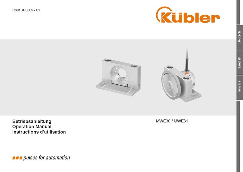
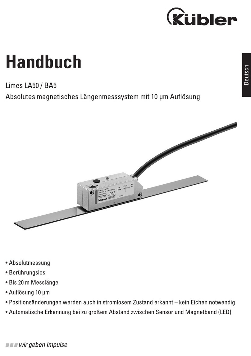
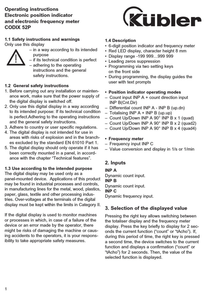
Kübler IN81 User manual

Manual
Inclinometer IN81
Inclinometer 1-dimensional
Inclinometer 2-dimensional
R67029.0002 Index 1

R67029.0002 EN
Publisher Kübler Group, Fritz Kübler GmbH
Schubertstr. 47
78054 Villingen-Schwenningen
Germany
www.kuebler.com
Application support Phone+49 7720 3903-952
Fax +49 7720 21564
Document no. R67029.0002
Document title Manual
Language version EN - German is the original version
Issue date 17.03.2017, Index 1
Copyright ©2016, Kübler Group, Fritz Kübler GmbH
Legal information All of the contents of this device description are subject to the
rights of use and copyrights of Fritz Kübler GmbH. Any
duplication, modification, further use or publication in other
electronic or printed media, as well as their publication in the
Internet, is subject to the previous written authorization of Fritz
Kübler GmbH.

1
Technical details
and characteristics
R67029.0002 EN - 2
Table of contents
Table of contents
1. Technical details and characteristics ...............................................................................4
1.1 Working temperature range..................................................................................................4
1.2 Supply voltage and current consumption..............................................................................4
1.3 Load at the output / max. output current...............................................................................4
1.4 Hardware characteristics......................................................................................................5
1.5 Function/status and diagnosis display ..................................................................................5
1.6 Supported standard measuring ranges.................................................................................5
1.7 Supported standard functions...............................................................................................5
1.8 Optional functions.................................................................................................................5
1.9 Orientation............................................................................................................................6
2. Electrical installation – Supply voltage.............................................................................7
2.1 Electrical installation.............................................................................................................7
2.2 Terminal assignment ............................................................................................................8
3. Function and status LED .................................................................................................10
3.1 LED display in normal operation.........................................................................................10
3.2 LED display during preset...................................................................................................10
3.3 LED display in programming mode.....................................................................................11
3.4 LED display in scaling mode: Analog measuring range......................................................11
3.5 LED display in scaling mode: Switching outputs (OPTIONAL!)...........................................12
3.6 LED display in sensor filter setting mode............................................................................12
4. Standard function.............................................................................................................13
4.1 1-dimensional inclinometer.................................................................................................13
4.2 2-dimensional inclinometer.................................................................................................14
5. User settings overview.....................................................................................................15
6. User settings.....................................................................................................................16
6.1 Preset function ...................................................................................................................16
6.2 Scaling the analog measuring range...................................................................................17
6.3 Setting the switching outputs..............................................................................................21
6.4 Setting of the sensor filter...................................................................................................23
6.5 Resetting to factory settings ...............................................................................................24
7. Sensor filter ......................................................................................................................25
8. Preset function restriction for the 2-dimensional inclinometer ....................................27
9. Timeout in programming mode.......................................................................................28

1
Technical details
and characteristics
R67029.0002 EN - 4
1. Technical details and characteristics
1.1 Working temperature range
-40 … +85°C
1.2 Supply voltage and current consumption
Output:
4 … 20 mA: 10 … 30 VDC max. 30,0 mA
0 … 10 V: 15 … 30 VDC max. 30,0 mA
0 … 5 V/
0.1 … 4.9 V/
0.5 … 4.5 V : 10 … 30 VDC max. 30,0 mA
1.3 Load at the output / max. output current
Output:
4 … 20 mA: at 10 VDC max. 200 Ohm
at 24 VDC max. 900 Ohm
0 … 10 V/
0 … 5 V/
0.1 … 4.9 V/
0.5 … 4.5 V: 1 kOhm load resistance / max. output current: 10 mA

1
Technical details
and characteristics
R67029.0002 EN - 5
1.4 Hardware characteristics
2-dimensional sensor: Measuring range per axis max. ± 85°
1-dimensional sensor: Measuring range per axis max. ± 180° (0 … 360°)
Analog output resolution (D/A) 4096 steps (12 bits)
Internal cycle 20 ms
Settling time 1 ms
Table 1
1.5 Function/status and diagnosis display
By RGB LED (red/green/blue + mixed colors: violet / orange)
1.6 Supported standard measuring ranges
• 0 … 10 V
• 0 … 5 V
• 0.1 … 4.9 V
• 0.5 … 4.5 V
• 4 … 20 mA
1.7 Supported standard functions
• Scaling of the analog measuring range per measuring axis
• Sensor filter adjustable in 7 steps
• Preset function (excepted for the measuring range: 2-dimensional ± 85°)
• Resetting to factory settings
1.8 Optional functions
• 2 adjustable switching outputs

1
Technical details
and characteristics
R67029.0002 EN - 6
1.9 Orientation
1-dimensional 0 … 360°
Figure 1
2-dimensional ±85°
Figure 2

2
Electrical installation
– Supply voltage
R67029.0002 EN - 7
2. Electrical installation – Supply voltage
This chapter contains information about the electrical installation, configuration and commissioning of
the inclinometer IN81 analog U/I.
Figure 3
2.1 Electrical installation
Switch off the plant!
Make sure that the whole plant remains switched off during the electrical
installation.
Electrical installation requires connectors or connection cables (see data
sheet).
NOTICE

2
Electrical installation
– Supply voltage
R67029.0002 EN - 8
2.2 Terminal assignment
1-dimensional
Table 2
2-dimensional
Table 3

2
Electrical installation
– Supply voltage
R67029.0002 EN - 9
+V: Supply voltage +V DC
0V Supply voltage GND (0V)
Uout+ X X-axis voltage output
Uout- X GND for X-axis voltage output
Uout+ Y Y-axis voltage output
Uout- Y GND for Y-axis voltage output
Uout+ Voltage output, 1-axis version
Uout- GND for voltage output, 1-axis version
Uout + Inverted voltage output, 1-axis version
Uout - GND for inverted voltage output, 1-axis version
Iout+ X X-axis current output
Iout- X GND for X-axis current output
Iout+ Y Y-axis current output
Iout- Y GND for Y-axis current output
Iout+ Current output, 1-axis version
Iout- GND for current output, 1-axis version
Iout+ Inverted current output, 1-axis version
Iout - GND for inverted current output, 1-axis version
Teach 1 Input 1 for various teaching functions
Teach 2 Input 2 for various teaching functions
DO1 Digital output 1
DO2 Digital output 2
Connect the shield to the inclinometer housing.
If possible, mount all cables with traction relief.
Check the maximum supply voltage on the device.
NOTICE

3
Function and
status LED
R67029.0002 EN - 10
3. Function and status LED
The device is equipped with a RGB LED for displaying status and error messages
3.1 LED display in normal operation
Display RGB LED Meaning Addition
LED off
Device is not powered
Green constantly
on
Normal operation
Red constantly
flashing
System error Contact the service
Table 4
3.2 LED display during preset
Display
RGB LED
Meaning
Addition
Green
6 x flashing
6 x
Preset completed successfully
for measuring axis 1
Orange
6 x flashing
6 x
Preset completed successfully
for measuring axis 2 Only available for
inclinometers with 2
measuring axes!
Red
6 x flashing
6 x
Preset FAILED Preset outside of the allowable
measuring range
Table 5

3
Function and
status LED
R67029.0002 EN - 11
3.3 LED display in programming mode
Display RGB LED Meaning Addition
Orange » Violet » Blue
in repeating sequences
You are in the programming
mode
Red » Green » Blue in a
single sequence
The device is reset to factory
setting
Orange » Violet in
repeating sequences
You are in the scaling mode of
the analog measuring range or
of the switching outputs
Orange constantly
flashing
You are in the scaling mode of
the analog measuring range
Violet constantly
flashing
You are in the scaling mode of
the switching outputs
Green
6 x flashing
6 x
User input detected on the
Teach input and performed
successfully
Red
6 x flashing
6 x
User input on the Teach input
rejected! E.g. selected measuring range
too small
Table 6
3.4 LED display in scaling mode: Analog measuring range
Display RGB LED Meaning Addition
Green » Orange in
repeating
sequences
You selected measuring axis 1
in order to scale its analog
measuring range
Red » Orange in
repeating
sequences
You selected measuring axis 2
in order to scale its analog
measuring range
Only available for
inclinometers with 2
measuring axes!
Table 7

3
Function and
status LED
R67029.0002 EN - 12
3.5 LED display in scaling mode: Switching outputs
(OPTIONAL!)
Display
RGB LED
Meaning
Addition
Green » Violet in
repeating
sequences
You selected measuring axis 1 in
order to set its switching output
Red » Violet in
repeating
sequences
You selected measuring axis 2 in
order to set its switching output Only available for
inclinometers with 2
measuring axes!
Table 8
3.6 LED display in sensor filter setting mode
Display RGB LED Meaning Addition
Blue constantly on
Sensor filter = OFF
Blue flashing 1 x
1 x
Sensor filter = 0.1 Hz
Blue flashing 2 x
2 x
Sensor filter = 0.3 Hz
Blue flashing 3 x
3 x
Sensor filter = 0.5 Hz
Blue flashing 4 x
4 x
Sensor filter = 1.0 Hz
Blue flashing 5 x
5 x
Sensor filter = 2.0 Hz
Blue flashing 6 x
6 x
Sensor filter = 5.0 Hz
Blue flashing 7 x
7 x
Sensor filter = 10.0 Hz
Table 9

4
Standard function
R67029.0002 EN - 13
4. Standard function
4.1 1-dimensional inclinometer
The single-axis inclinometer is factory-equipped with a measuring range of 0 … 360°.
According to the selected output type, a linear output signal is emitted by the analog outputs.
•Analog output 1:
oincreasing measurement signal for positive direction of movement.
•Analog output 2:
omeasurement signal inverted with respect to analog output 1.
odecreasing measurement signal for positive direction of movement.
After 360° the system continues from 0°.
Figure 4
For the measuring range of 0 … 360° the switching outputs switch at 10° / 350°!
If a new measuring range is taught or factory-set to < 360°, the switching outputs switch at the
beginning and at the end of the measuring range.
OPTION : Limit switch

4
Standard function
R67029.0002 EN - 14
Example for a measuring range of 0 … 180°:
Figure 5
4.2 2-dimensional inclinometer
The 2-dimensional inclinometer is factory-set with a measuring range of +/-85°. Depending on the
analog output type (4 … 20mA / 0 … 10V/…), a linearly increasing measurement signal is emitted for
every measuring axis.
Analog output X: Measurement signal – X-axis movement
Analog output Y: Measurement signal – Y-axis movement
Figure 6
If the inclinometer is equipped with the limit switch function, the switching outputs switch when the
analog measuring range limits are reached.
OPTION : Limit switch

5
User settings
overview
R67029.0002 EN - 15
5. User settings overview
Normal operation
T1 + T2 >10 sek.
RESET
PRESET
AX IS 1AX IS 2
T1 >1 sek. T2 >1 sek .
Normal operation
OK OK
P ROG -Mode
T1 + T2 > 2 sek.
Teach switch outputs
Teach an alog limits
T1 > 2 sek.T2 > 2 sek.
AX IS 1AX IS 2
NULL
Postion
T1 >1 sek. T2 >1 sek .
NULL
P osi ti on
En d po st io n En d po st io n
T1 >1 sek. T2 >1 sek .
Normal operation
T1 >2 sek. T2 >2 sek .
OK
Error
2-dim ens io nal
AX IS 1AX IS 2
Sta rt p o sti on
T1 >1 sek.T2 >1 sek .
Sta rt p o sti on
En d po st io n En d po st io n
T1 >1 sek. T2 >1 sek .
Normal operation
T1 >2 sek. T2 >2 sek .
DO1DO2DO1
DO2
1-dim ens io nal
T1 >2 sek.
AX IS 1
Sta rt p o sti on
T1 >1 sek.
En d po st io n
T1 >1 sek.
Normal operation
Normal operation
Or de r
2-dim ens io nal1-dim ens io nal
AX IS 1
Sta rt p o sti on
T1 >1 sek.
En d po st io n
T1 >1 sek.
T1 >2 sek.
Normal operation
2-dim ens io nal
1-dim ens io nal
AX IS 1
T1 >1 sek.
OK
Normal operation
6x100ms
50/50
6x100ms
50/50
6x100ms
50/50
500ms
50/50
1000ms
50/50
500ms
50/50
500ms
50/50
500ms
50/50
500ms
50/50
500ms
50/50
6x100ms
50/50
6x100ms
50/50
OK
Error
6x100ms
50/50
6x100ms
50/50
OK
Error
6x100ms
50/50
6x100ms
50/50
OK
Error
6x100ms
50/50
6x100ms
50/50
OK
Error
6x100ms
50/50
6x100ms
50/50
OK
Error
6x100ms
50/50
6x100ms
50/50
500ms
50/50
500ms
50/50
500ms
50/50
OK
Error
6x100ms
50/50
6x100ms
50/50
OK
Error
6x100ms
50/50
6x100ms
50/50
OK
Error
6x100ms
50/50
6x100ms
50/50
OK
Error
6x100ms
50/50
6x100ms
50/50
OK
Error
6x100ms
50/50
6x100ms
50/50
OK
Error
6x100ms
50/50
6x100ms
50/50
TE A CH - O UT P UT
T1 > 2 sek.
P ROG - FI LTER
T2 > 2 sek.
D ispla y fil te r sta ge
Filter OFF
F il te r 1
F il te r 2
F il te r 3
F il te r 4
F il te r 5
F il te r 6
F il te r 7
T1 >2 sek. T2 >2 sek .
UP DOWN
T1 + T2 >2 sek.
STORE
EX IT ?
NO
YES
Normal operation
OK
6x100ms
50/50
Error
OK
6x100ms
50/50
C han ge fi l te r?
NO
YES
500ms
50/50
Figure 7

6
User settings
R67029.0002 EN - 16
6. User settings
The inclinometer can be adapted to the customer application by means of two teach inputs. The
following functions are available to the user. They can be operated through the two teach inputs:
• Preset function (set a new reference point)
• Scaling of the analog measuring range
• Setting of the switching points of the optional limit switches.
• Setting of the sensor filter
• Resetting to factory setting
6.1 Preset function
1-dimensional inclinometer
Preset
Action
RGB LED
Description
Initial state:
Device in normal
operation
constantly on
The device is in normal operation
6 x Apply +V at teach input 1 for > 1 second.
The LED flashes 6 x green after preset completion.
constantly on The output signal of analog outputs 1 & 2 is set to 50% of the
measuring range.
Example: Measuring range = 0 … 10V -> Output after
preset = 5V
The device is in normal operation again.
Table 10

6
User settings
R67029.0002 EN - 17
2-dimensional inclinometer
Preset axis X (not available for measuring range +/- 85º!)
Action RGB LED Description
Initial state: Device
in normal operation,
axis X <= +/-15°
constantly on The device is in normal operation and in factory setting.
The X-axis is located in the measuring range of +/- 15°.
No preset is possible outside of the range +/-15°!
= > 1 Sec.
6 x Apply +V at teach input 1 for > 1 second.
The LED flashes 6 x green after preset
completion.
constantly on The output signal of analog output 1 is set to 50% of the
measuring range.
Example: Measuring range = 0 … 10V -> Output after
preset = 5V
The device is in normal operation again.
Table 11
Preset axis Y(not available for measuring range +/- 85º!)
Action
RGB LED
Description
Initial state: Device
in normal operation,
axis Y <= +/-15°
constantly on The device is in normal operation and in factory setting.
The Y-axis is located in the measuring range of +/- 15°.
No preset is possible outside of the range +/-15°!
= > 1 Sec.
6 x
Apply +V at teach input 2 for > 1 second.
The LED flashes 6 x orange after preset
completion.
constantly on The output signal of analog output 2 is set to 50% of the
measuring range.
Example: Measuring range = 0 … 10V -> Output after
preset = 5V
The device is in normal operation again.
Table 12
6.2 Scaling the analog measuring range
** The switching points of the optional switching outputs are adapted to the new scaled analog
measuring range if they have not been already taught by the user!

6
User settings
R67029.0002 EN - 18
1-dimensional inclinometer
Scale the measuring range within 0 … 360º
Action RGB LED Description
Initial state:
Device in normal
operation
constantly on The device is in normal operation and in factory setting.
= > 1 Sec.
> > > Apply +V at teach inputs 1 & 2 for > 1sec.
The device is switched to programming mode. This is
indicated by the repeated LED flashing sequence Orange »
Violet » Blue.
= > 1 Sec.
> >
Apply +V at teach input 1 for > 1sec.
The device is switched to scaling mode. This is indicated by
the repeated LED flashing sequence Orange » Violet.
= > 1 Sec.
> > Apply +V at teach input 1 for > 1sec.
The device is switched to the scaling mode.of the analog
measuring range. The LED flashes orange.
= > 1 Sec.
> > Apply +V at teach input 1 for > 1sec.
The measuring axis to be scaled is selected.
This is indicated by the repeated LED flashing sequence
Green » Orange.
Position the inclinometer at the starting position of the required
measuring range.
= > 1 Sec.
6 x Apply +V at teach input 1 for > 1sec.
The starting position of the required measuring range is saved.
The LED flashes 6 x green after successful saving of the
starting position.
Move the inclinometer in the positive direction to the end
position of the required measuring range.
= > 1 Sec.
6 x Apply +V at teach input 1 for > 1sec.
The end position of the required measuring range is
saved. The new measuring range is calculated and
set.
The LED flashes 6 x green after successful saving of the
end position.
6 x In case of an error, the LED flashes 6 x red. The desired
measuring range cannot be saved.
The device returns to the normal mode with the factory settings.
Initial state:
Device in normal
operation
constantly
on
The device is in normal operation again.
The new measuring range is set and permanently stored in the
device.
Table 13

6
User settings
R67029.0002 EN - 19
2-dimensional inclinometer
Measuring range X axis within +/- 85º
Action RGB LED Description
Initial state:
Device in normal
operation
constantly on The device is in normal operation and in factory setting.
= > 1 Sec.
Apply +V at teach inputs 1 & 2 for > 1sec.
The device is switched to programming mode. This is
indicated by the repeated LED flashing sequence
Orange » Violet » Blue.
= > 1 Sec.
Apply +V at teach input 1 for > 1sec.
The device is switched to scaling mode. This is indicated by
the repeated LED flashing sequence
Orange » Violet.
= > 1 Sec.
Apply +V at teach input 1 for > 1sec.
The device is switched to the scaling mode.of the analog
measuring range. The LED flashes Orange.
= > 1 Sec.
Apply +V at teach input 1 for > 1sec.
The measuring axis X to be scaled is selected.
This is indicated by the repeated LED flashing sequence
Green » Orange.
Position the X axis of the inclinometer at the reference position
of the required measuring range.
This position is saved as 0° and 50% of the output signal is
assigned to analog output 1. You are now positioned at the
center of the required measuring range.
Example: Measuring range = 0 … 10V Output = 5V
Position = 0°
= > 1 Sec.
6 xApply +V at teach input 1 for > 1sec.
The reference position of the required measuring range is
saved. The LED flashes 6 x green after successful saving of
the reference position.
Position the X axis of the inclinometer at the end position of the
required measuring range.
= > 1 Sec.
6 x Apply +V at teach input 1 for > 1sec.
The end position of the required measuring range is
saved. The new measuring range is calculated and
set.
The LED flashes 6 x green after successful saving of the
end position.
6 x In case of an error, the LED flashes 6 x red. The desired
measuring range cannot be saved.
The device returns to the normal mode with the factory settings.
Initial state:
Device in normal
operation
constantly
on
The device is in normal operation again.
The new measuring range is set and permanently stored in the
device.
Table 14
Table of contents
Other Kübler Measuring Instrument manuals

Kübler
Kübler Limes LA50 User manual

Kübler
Kübler Ants LEB02 User manual

Kübler
Kübler Ants LEB01 User manual

Kübler
Kübler CODIX 134 User manual

Kübler
Kübler CODIX 136 User manual

Kübler
Kübler CODIX 52P User manual

Kübler
Kübler CODIX 54P User manual

Kübler
Kübler CODIX 52P User manual

Kübler
Kübler Ants LEB02 User manual

Kübler
Kübler Ants LES02 User manual

Kübler
Kübler SAEJ1939 User manual

Kübler
Kübler MWE30 User manual

Kübler
Kübler Ants LEB02 User manual

Kübler
Kübler MWE20 User manual

Kübler
Kübler CODIX 525 User manual

Kübler
Kübler CODIX 54P User manual

Kübler
Kübler SMC2.4 User guide

Kübler
Kübler Limes LA10 User manual

Kübler
Kübler IN88 User manual

Kübler
Kübler codix 130 User manual