K-Systems G85 User manual

1
K-SystemsTM G85 Mini Incubator
User Manual
K22074 Version 3.0

User Manual - G85
2
Contents
1General information & service..........................................................................................................................3
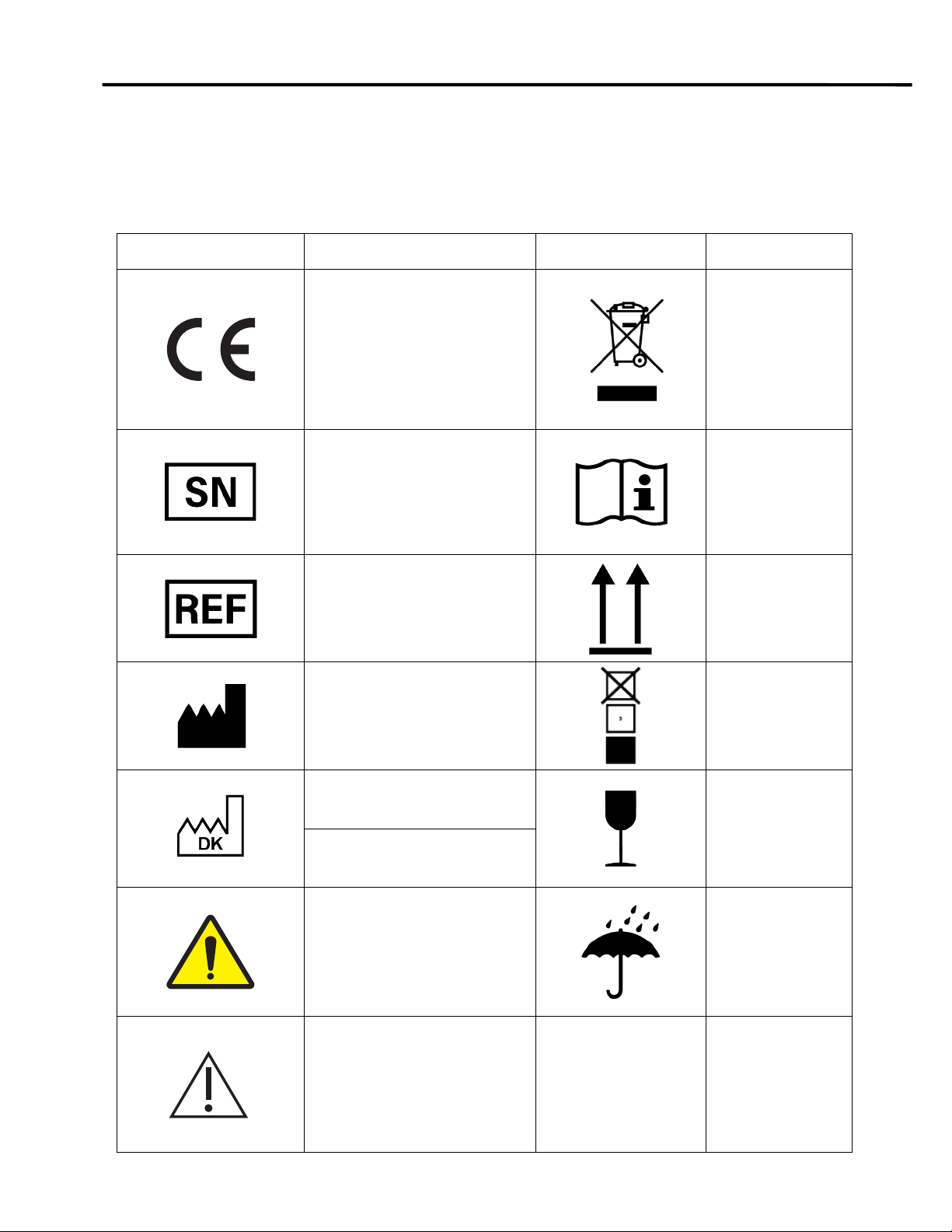
2Symbols glossary ..............................................................................................................................................4
3Unpacking and inspection ................................................................................................................................5
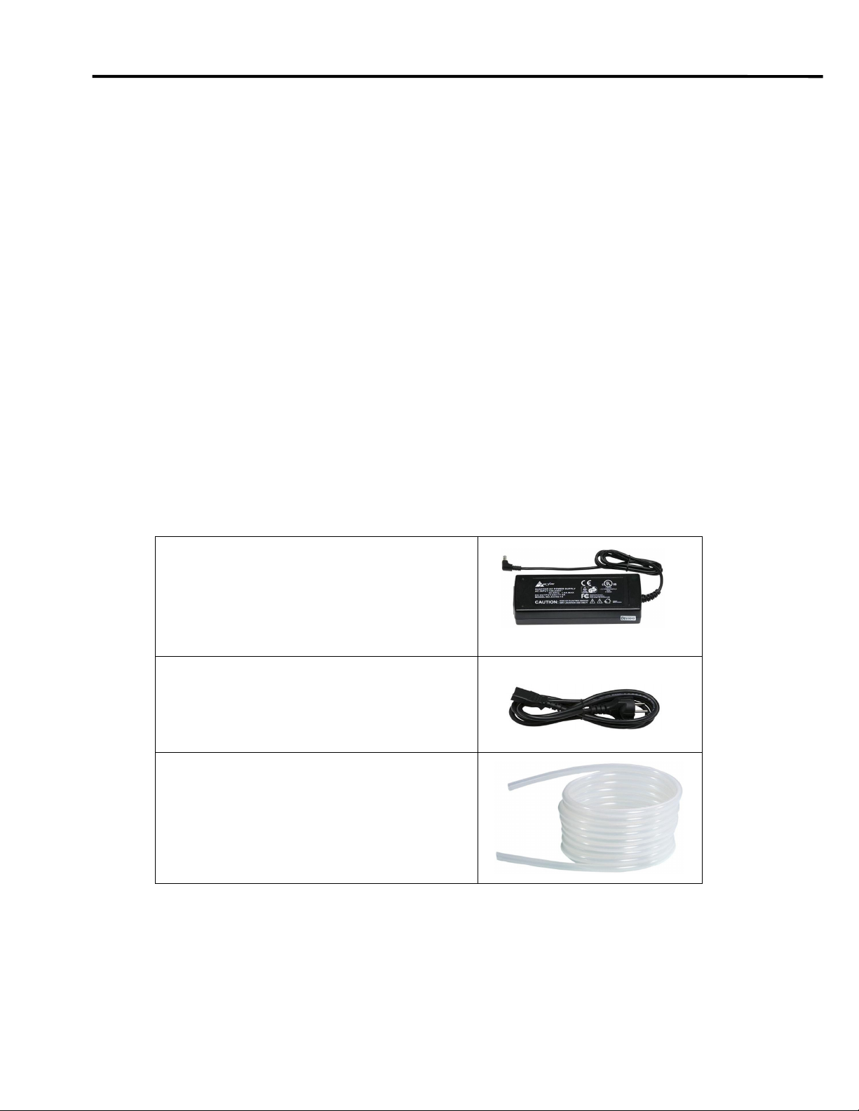
4Parts supplied with incubator...........................................................................................................................5
4.1 Standard accessories.................................................................................................................................5
4.2 Optional accessories..................................................................................................................................6
5User manual .......................................................................................................................................................7
5.1 Intended purpose .......................................................................................................................................7
5.2 Product description.....................................................................................................................................7
6Features and operation .....................................................................................................................................8
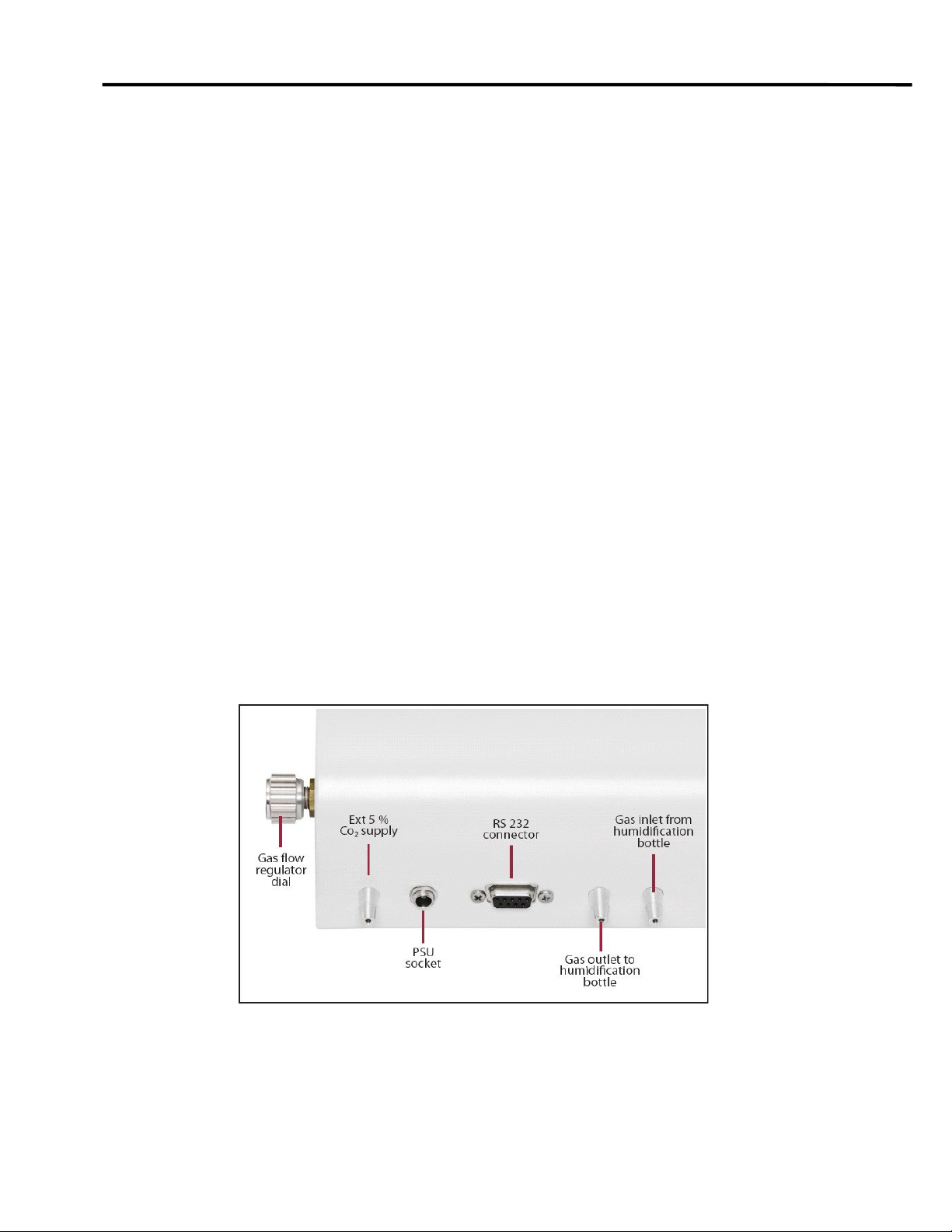
6.1 Set up of apparatus....................................................................................................................................8
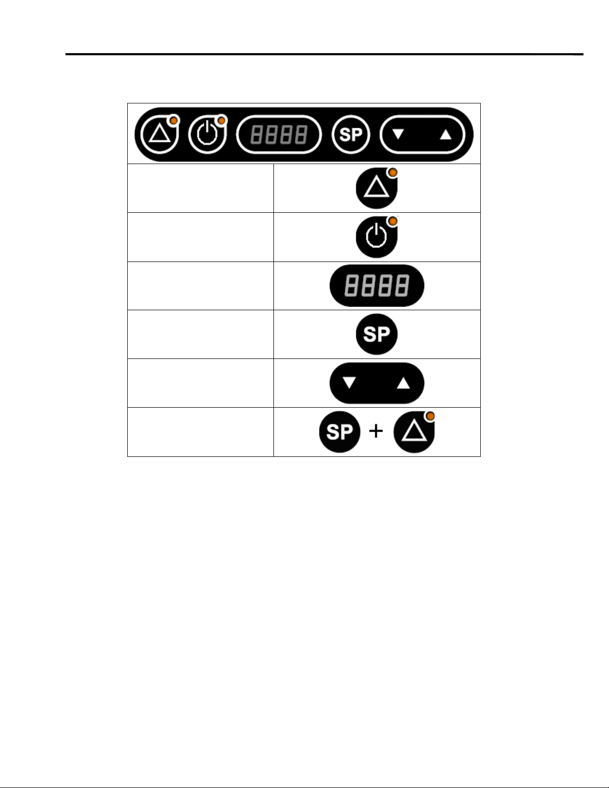
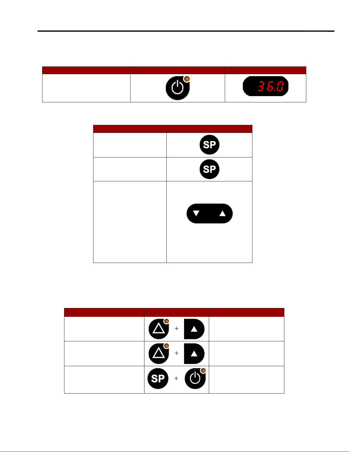
6.2 Keyboard functions.....................................................................................................................................9
6.3 Operating the heated compartment..........................................................................................................10
6.4 Temperature setting and control ..............................................................................................................10
6.5 Combination keys.....................................................................................................................................10
6.6 Gas flow setting........................................................................................................................................ 11
6.6.1 Why gassing?...........................................................................................................................................11
6.6.2 Working gas pressure ..............................................................................................................................11
6.6.3 Humidifying the gas mixture .....................................................................................................................12
6.6.4 Purge function ..........................................................................................................................................13
6.7 Temperature/Flow alarm ..........................................................................................................................14
6.7.1 Temperature alarm...................................................................................................................................14
6.7.2 Gas flow alarm .........................................................................................................................................14
6.8 Warming up..............................................................................................................................................15
7Menu function ..................................................................................................................................................16
7.1 Overview of options..................................................................................................................................17
7.2 UNIT.........................................................................................................................................................18
7.3 RS232 ......................................................................................................................................................19
7.4 TUNE .......................................................................................................................................................20
7.5 Integral Time (INT.T)................................................................................................................................21
7.8 HEAT........................................................................................................................................................23
7.9 Automatic Start (A-ST) .............................................................................................................................24
7.10 HOUR 25
7.11 REST 26
8User maintenance............................................................................................................................................27
8.1 Cleaning ...................................................................................................................................................27
8.2 Calibration ................................................................................................................................................27
9Trouble shooting..............................................................................................................................................28
10 Technical data..................................................................................................................................................29
11 Disposal and recycling....................................................................................................................................29
12 Warranty information and limits on liability ..................................................................................................30
13Customer service contact details ..................................................................................................................32

User Manual - G85
3
1
General information &service
This manual isprotected by copyright, allrights reserved, and no part hereof may be
photocopied or reproduced in any form without the prior written, consent of CooperSurgical, Inc.
Users of CooperSurgical K-SYSTEMSTM products should not hesitate to contact us if there are
any unclear points or ambiguities in this manual.
CooperSurgical,Inc.
95 Corporate Drive
Trumbull, CT06611, USA
Tel: +45 46 79 02 02
Fax: +45 46 79 03 02
fertility.coopersurgical.com
Contact Details for Customers inthe USA
Tel: 800-243-2974
Fax: 800-262-0105
fertility.coopersurgical.com
CAUTION: If the equipment is used in a manner not specified by this manual,
the safety of the user may be at risk and the equipment may be damaged. Always
use the equipment as outlined in this instruction manual.

User Manual - G85
4
2
Symbols glossary
Source: ISO 15223-1
Symbol Meaning Symbol Meaning
In accordance with Low
Voltage Directive 2014-35-EU
Do not dispose of
product with
normal waste.
Dispose of in
accordance with
the EU WEEE
Directive
Serial number Consult
instructions for
use
Catalogue number This way up
Manufacturer Stacking limited to
3 units
Fragile, handle
with care
WARNING: Indicates a
potentially hazardous situation
which, if not avoided, could
result in serious injury or death
Keep dry
CAUTION: Indicates a
potentially hazardous situation
which, if not avoided, could
result in minor or moderate
injury
Country of manufacture
Date of manufacture

User Manual - G85
5
3
Unpacking and inspection
•
Unpack the equipment.
•
Check the packing list to ensure all accessories are there.
•
Examine the packing material carefully for separately packed items.
•
Check the incubator for external surface damage.
•
Check that the display is not broken or damaged.
•
Check that the lids and gas flow regulator knob operate correctly without any
hindrance.
4
Parts supplied with incubator
4.1
Standard accessories
24Vmains adapter (PSU)
Order code: 51122
Mains Cable
Standard Schuko – Oder code: 52768
UK – Order code: 53886
US – Order code: 52773
Silicone tube
Order code: 11066

User Manual - G85
6
4.2
Optional accessories
The following warming blocks can be purchased for use with the incubator.
Warming block B16
Holds two culture dishes
B16F – Falcon 353001
Order code:26059
B16N – NUNC 150318
Order code: 26060
Warming block B24
Holds one center well dish
Falcon 353653
Order code: 26027
Warming block B25
Holds one 60 mm culture dish
Falcon 353002
NUNC 150288
Order code: 26028
Warming block B26
Holds one 4-well Falcon dish withlid
Falcon 353654
Order code: 26031
Warming block B28
Holds one 4-well dish
NUNC 176740
Order code: 26029
Warming block B29
Holds one 5-well dish
MiniTüb 19021/0005
Order code: 26030

User Manual - G85
7
5
User manual
5.1
Intended purpose
The CooperSurgical K-Systems G85 Mini Incubator isdesigned for keeping gametes and
embryos in a controlled environment.
5.2
Product description
The chambers and aluminum warming blocks maintain a preset temperature in the range
ambient to 42°C. The temperature on the display in increments is electronically controlled
by a PID controller and can be read on the displaying in increments of 0.1°C.
The G85 features heated lids. The bottom partismade from thick aluminum that gives
ideal temperature distribution. Interchangeable aluminum warming blocks holding a variety
of culture dishes areavailable.
The G85 features a built-in digital flow meter with a possible flow of0- 29 liters perhour
and a humidification system.
The G85 has also a purge function enabling a quick CO2level recovery within the
chambers. The recovery time is 15 seconds with a pressure of 0.5 bar.
Note:
The atmosphere in the chambers may be controlled by flushing with a gas
mixture. Use only 5% CO
2
in air.

User Manual - G85
8
6
Features and operation
6.1
Set up of apparatus
Connect the unit to the PSU and the PSU to the mains wall socket.
To power up the unit, press the heat on button on the keyboard. The display will indicate
the current temperature.
Adjust the gas flow with the control knob on the right-hand side of the unit. The valve
controlling the flow is a precision valve with a short span from closed to open, so adjust with
slow movements. A hint for adjusting is to close it fully and then open it gently.

User Manual - G85
9
6.2
Keyboard functions
Purge
Heat ON/Off
LED Display
Setpoint
Arrow keys UP/DOWN
Alarm

User Manual - G85
10
6.3
Operating the heated compartment
Action
Key
Press heat ON/OFF key to
show the actual
temperature.
6.4
Temperature setting and control
Action
Key
Press setpoint key and
the set temperature is
shown.
Press and hold setpoint
key.
While holding the
setpoint key in, press
either the arrow UP or
arrow DOWN key to
raise or lower the set
temperature.
When the desired
temperature is
reached, let go of the
setpoint key.
Note: The setpoint can be adjusted to a reading between ambient and 49.9 ˚C.
6.5
Combination keys
Action
Key
Display
Press alarm and UP key.
The keyboard is locked.
Press alarm and UP key.
The keyboard is
unlocked.
Press Heat ON/OFF and
setpoint key.
Switches between
temperature and time.

User Manual - G85
11
6.6
Gas flow setting
The display can switch between temperature and flow rate.
The flow rate is shown in the display by the integrated digital flow meter in the G85.
Action
Key
Press arrow key either up or
down one time.
Now the flow rate in liter per hour
will be shown.
The flow rate can be adjusted between 0 – 29 l/h.
If the flow becomes larger than 29 l/h the display will indicate “Hi”.
Action
Key
Press arrow key either up or
down once again to change to
the display of temperature.
6.6.1
Why gassing?
Most of the culture media which are used in assisted reproduction techniques are sensitive
to changes in pH. Culture media must be maintained at a pH about 7.4. This can be
obtained by gassing with atmosphere of 5% or 6% CO2. Refer to culture media instructions
for use for any humidification requirements.
6.6.2
Working gas pressure
Working gas pressure (inlet pressure on the G85) must be regulated to 0.5 bar by a
reduction valve. The reduction valve must be a high-quality unit of the pressure type that
can be adjusted precisely in the 0-1 bar range.
The flow rate on the G85 must be adjusted to a specific level in accordance with the use of
the unit.
Frequent openings of the lids will require higher flow rates.
Note:
Any use of flow type regulators or inadequate quality pressure
type regulators will cause the flow on the G85 to be unstable and drift.
Below is listed the full recovery rates for CO2level in both chambers in minutes.
This can be used as guideline for the use.
*Flow setting in display of G85.
**Time it will take to recover CO2level after a chamber has been opened at the above flow
setting.
Flow (l/h)
*
10
28
50
Time (min)
**
12
2.8
0.9

User Manual - G85
12
If the use necessitates low recovery times, either a constant high flow must be used or
purging the chambers by setting the flow level at a high rate for 2-3 minutes.
A flow of 10 l/h will be sufficient to sustain the CO2levels in the chambers when the lids
are not opened. The flow rate should at no time be kept under 8 l/h.
A flow rate of 15-20 l/h should be adequate under most conditions without the use of
manual purge.
6.6.3
Humidifying the gas mixture
In order to avoid gassing with cold and dry gas, the built in humidifier can be used.
Connect the tubes as shown on the picture below.
WARNING: Always route the gas as shown or permanent damage to the
airflow sensors may occur.
If the humidification system is not used and the gassing is done with dry gas, a silicone
tube U loop must be connected between the outlet and inlet for the humidification bottle.
CAUTION:The flow sensor may be damaged by water ingress from
the humidification bottle.
The fault is registered by the user getting a “0” reading in the display when an obvious
flow can be seen as bubbles in the humidification flask.
When adjustment in the flow rate is done on the regulator valve on the side of the G85, no
changes can be seen to the flow reading in the display. It will stay at “0” disregarding the
flow.

User Manual - G85
13
The fault occurs because of under pressure in the gas supply when the G85 is not in use.
If the user shuts off the gas supply only on the bottle or the external regulator an under
pressure will develop. The under pressure will draw back liquid from the humidification
bottle through the gas outlet to bottle tube and into the G85 where it will damage the flow
sensor.
If the user remembers to completely close the regulator valve on the side of the G85 no
such problem will occur.
•
Alternatively, the exterior 5% CO2supply tube should be disconnected from the G85
when the G85 is not in use.
Or:
•
The gas outlet to bottle tube disconnected when the G85 is not in use.
If the problem has occurred, the gas flow sensor PCB will need to be replaced.
6.6.4
Purge function
The G85 has a purge function enabling to have a fast recovery of the CO2level within the
chambers. This function is to be used when the lid of the chambers has been opened in
order to place or remove culture dishes. The purge time is 15 seconds.
Action
Key
Press the alarm key to
activate the purge
function.
When activated a “Pu”
indication appears on the
display.

User Manual - G85
14
6.7
Temperature/Flow alarm
The G85 has one alarm which is activated on two events:
•
Temperature deviations (high or low)
•
Gas flow
6.7.1
Temperature alarm
The temperature alarm indicates too high or too low temperature.
The alarm will be activated if the temperature rises or falls more than 0.5°C from the
setpoint.
There will be an acoustic signal and the red LED light in the alarm key will be activated.
Action
Key
Press setpoint key and alarm key to mute
the acoustic signal.
Press setpoint key and alarm key once
again to bring the signal back on.
Note:
The red LED and the acoustic signal will turn off if the temperature or gas flow
stabilizes again to the setpoint level.
6.7.2
Gas flow alarm
The gas flow alarm will be activated if the flow is higher than 29 l/h. The
display will then show “hi”.
The alarm will also be activated if the flow is “on”, and the heat “off”.
In this case the display will show “f.on”.
Note:
The maximum flow is 29 l/h. The G85 will not be damaged by
a higher flow as long as the gas flow is kept below 100 l/h.

User Manual - G85
15
6.8
Warming up
Warming up from 20.0°C to setpoint takes less than 30 minutes, under normal conditions.
When a cold item is placed in either of the chambers it may need up to 40 minutes to
stabilize, depending on the thermal mass of the object and the initial temperature.
G85 with two warming blocks in one chamber and humidifier is shown on the picture below.
Note:Always place a warming block in the chambers during warm up and be careful
with the heated area under the humidifier bottle as it will become hot.

User Manual - G85
16
7
Menu function
The user can access a number of advanced functions via the menu.
Action
Key
Display
Press and hold UP+DOWN
key for 3 seconds to enter the
menu.
The first option “UNIT” will
appear in the display.
Press UP/DOWN key to
navigate within the Menu.
While holding the setpoint
key in, press either the arrow
UP or arrow DOWN key to
change values within the
options.
Press and hold UP+DOWN
key for 3 seconds again to
exit the menu.

User Manual - G85
17
The menu consists of the 10 options listed below.
For further detail see the description on the following pages.
7.1
Overview of options

User Manual - G85
18
7.2
UNIT
In the UNIT option the displayed temperature unit can be set to either degrees Celsius
or Fahrenheit.
Follow these steps to navigate in the UNIT option.
Action
Key
Display
Press and hold UP+DOWN key for
3 seconds to enter the menu.
The menu "UNIT" will appear in
the display.
Press and hold setpoint key to
change values.
While holding the setpoint key in,
press either the arrow UP or arrow
DOWN key to select the required
type of unit.
When the required type has been
selected let go of the setpoint key.
Press and hold UP+DOWN key for
3 seconds to exit the menu.

User Manual - G85
19
7.3
RS232
The RS232 option is for serial communication and data logging of the temperature and
alarm conditions.
Follow these steps to navigate in the RS232 option.
Action
Key
Display
Press and hold UP+DOWN key for
3 seconds to enter the menu.
The option "UNIT" will appear in
the display.
Press DOWN key until the option
“RS232” appears in the display.
Press and hold setpoint key to
change values.
While holding the setpoint key in,
press either the arrow UP or arrow
DOWN key to select between
"ON" and "OFF".
“OFF”: The RS232 function is
turned off.
“ON”: Data is sent once every two
seconds.
When the required setting is
activated, let go of the setpoint
key.
Press and hold UP+DOWN key for
3 seconds to exit the menu.
Data logging the temperature valves during use.
Note:
RS232 communication is no longer supported.

User Manual - G85
20
7.4
TUNE
The TUNE option is for calibration of the displayed temperature.
If there is an offset between the value on the display and any measurements made with a
high precision external temperature sensor, this can be corrected.
The new temperature reading will be kept as the displayed value, with temperature control
conducted on this basis.
Follow thesesteps to navigate in the TUNE option.
Action
Key
Display
Press and hold UP+DOWN key for
3 seconds to enter the menu.
The menu "USER" will appear in
the display.
Press DOWN key until the option
“TUNE” appears in the display.
Press and hold setpoint key to
change values.
While holding the setpoint key in,
press either the arrow UP or arrow
DOWN key to select the value
temperature.
When the required setting is
activated, let go of the setpoint
key.
Press and hold UP+DOWN key for
3 seconds to exit the menu.
Note:
Any change in the factory set calibration should always be based on very
certain temperature measurements. CooperSurgical only recommend the
use of a high-quality PT-100 sensor that is calibrated with the precision
instrument used for measuring according to the manufacturers
specifications. Also ensure an optimal contact between the sensor and the
place measured. Use only a sensor type that iscorrect for the purpose
and of correct size. If in doubt, contact your local distributor or
CooperSurgical.
Other manuals for G85
1
Table of contents
Other K-Systems Laboratory Equipment manuals
Popular Laboratory Equipment manuals by other brands

Endress+Hauser
Endress+Hauser CAT820 operating instructions

Kinematica
Kinematica MICROTRON MB 550 instruction manual

Bruker
Bruker D8 Discover Standard operating procedure

V&P Scientific
V&P Scientific SpinVessel VP 418SV2-1-300FB-CC operating instructions

MRC
MRC COT Series Operation manual

Dionex
Dionex As Operator's manual