3
Split & Cuffed Insty-Pac Injection Tube Assembly
External Mounting Instructions
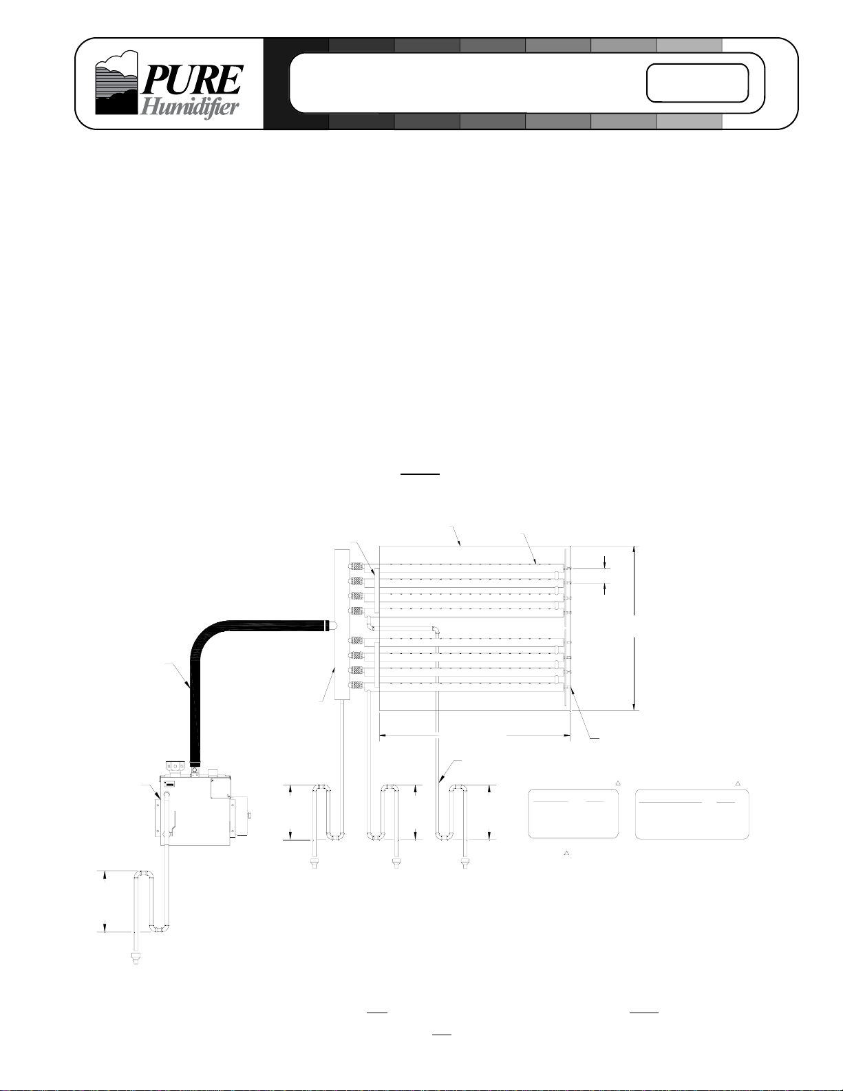
The Insty-Pac tube assembly supplied with humidifier(s), is designed for rapid dissipation of
steam. The tube assembly is designed for external AHU or duct mounting.
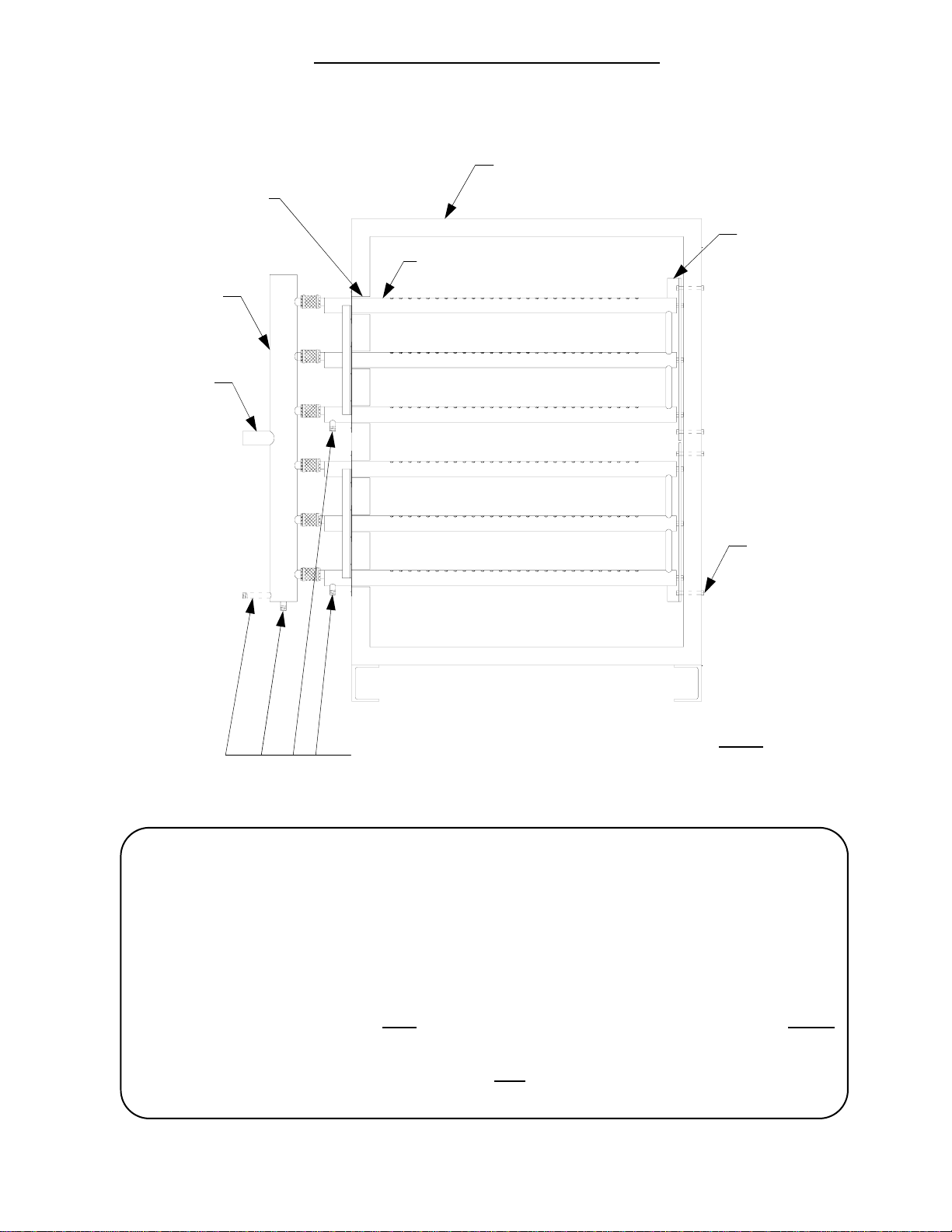
Verify Components
Unpack the components from the shipping container. Verify all components are checked off
according to the packing list and the COMPONENTS IDENTIFICATION DRAWING (Fig. 2).
Report any missing pieces to your local PURE Humidifier Co. representative immediately.
Location
1. Mount the injection tube assembly in the AHU or duct work as shown on the
project plans or as indicated by the engineer.
2. Install the injection tube with the 3/4”-NPT drain connection, located on the tube
header, directed towards the bottom of the AHU or duct.
3. Install the tube assembly so that the injection tubes are level within the AHU or duct.
4. Install the tube assembly with the steam discharge ports facing upwards.
5. The tube assembly should be centered in the AHU or duct height with an even
distance between the bottom tube and the casing floor and the top tube and the casing
ceiling.
Mounting
1. Cut a slot in the AHU or duct wall that is the same height as the HEADER and 1 1/2”
wide (see Fig. 3).
2. Slide the UPPER injection tube bank assembly through the access slot (cut in steps
above). Secure the END BRACKET to the AHU or duct wall with 3/8-16 UNC
fasteners (by others). The END BRACKET must be located so that the tubes are level
(see Fig. 3). Repeat the same steps with each remaining tube bank assembly.
3. Slip one side of each FLEXIBLE CONNECTORS onto the 1" diameter stub-outs on t h e
TUBE BANKS and secure the FLEXIBLE CONNECTORS with one screw clamp per
stub-out (see Fig. 2 & 3).
4. Slide the HEADER stub-outs into the open end of the FLEXIBLE CONNECTOR on the
TUBE BANKS. Secure each tube to the FLEXIBLE CONNECTOR by tightening the
matching screw clamp (see Fig. 2 & 3).
5. Seal the openings where the injection tubes penetrate through the AHU or duct wall w i t h
the duct plates provided (see Fig. 3).
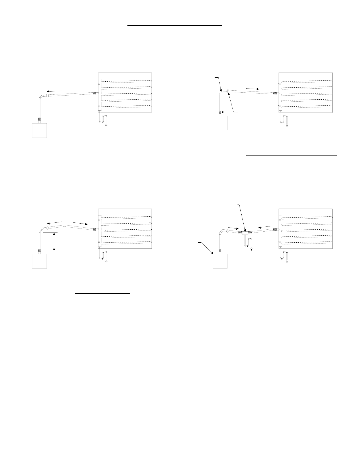
6. Connect steam supply and condensate piping to humidifier as illustrated on Fig. 1.
NOTE: For tube assemblies over 48” (122 cm) in length, allow for 1/2” (1.3 cm) of linear
expansion of tubes. Not allowing for this expansion could cause system performance
issues or cracking of welds.