K1EL WKmini USB WinKeyer User Manual WKmini B
WKmini Rev B User Manual 2/16/2022 Rev 1.2 Page 2
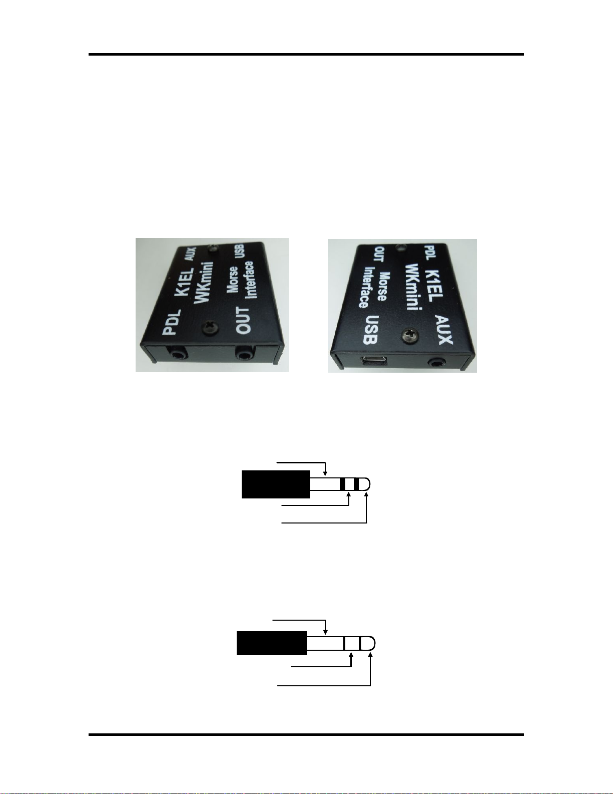
Introduction
This document will describe WKmini and its various interfaces. All the information you will need to
connect WKmini to your station will be included in this manual along with specific guides for
getting it working with N1MM+ Logger, HRD/DM780, N3FJP AC Log, and MRP40.
What is WinKeyer and why do I need it ?
Due to timing latencies inherent in multi-threaded operating systems like MS Windows, it is very
difficult to generate accurately timed Morse in software. All it takes is a higher priority task to
demand service and Morse generation will be delayed which results in wrongly timed dits, dahs,
or the spacing between them. A WinKeyer based device, like WKmini, attaches to a PC’s USB
port and appears as a serial com port to an application running on the PC. The application,
instead of generating Morse in software, sends the letters to WKmini. The application has full
control over sending speed as well as weighting, spacing, and PTT generation. WKmini has a
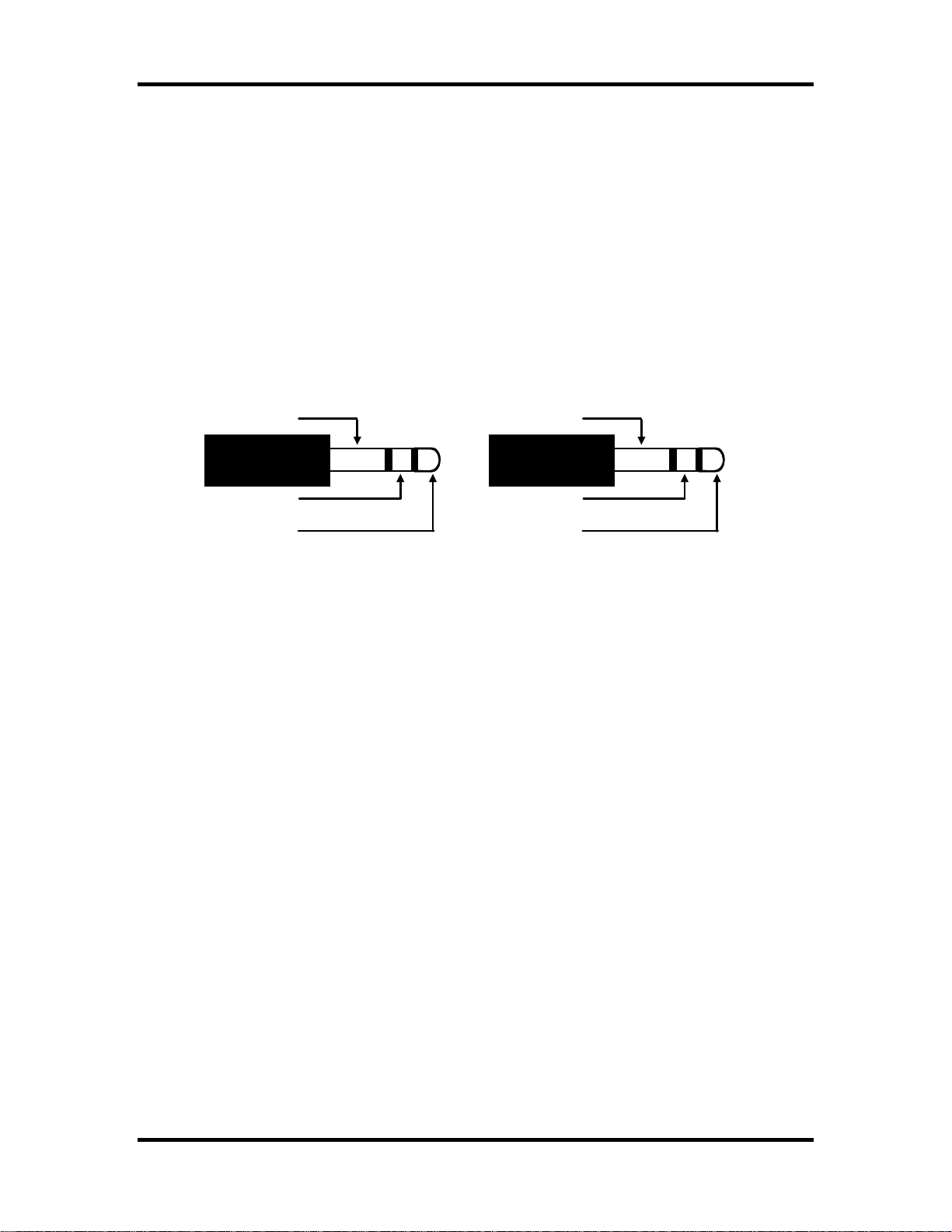
paddle interface so a user can break in immediately to handle fast exchanges in contest
situations. Electrically isolated keying outputs provide safety and prevent ground loops. Two
separate keying outputs allow the user to run two different radios from one keyer without
swapping cables. WKmini Rev B has two differences over Rev A. First, it uses a CH340 USB
controller instead of a FTDI controller in Rev A. The other difference is that Rev B moves Key 2
to the AUX port. Like Key 1, This port is optically coupled through a solid state relay. Maximum
voltage on either port is +/- 60 V.
WKmini Features
•USB 2.0 Interface with Mini type 3 connector •Uses K1EL’s latest WK3 IC
•Iambic CW Paddle Interface •Adjustable Speed 5-99 WPM
•Iambic A, B, Ultimatic & “Bug” paddle modes •Adjustable Weighting and dit/dah ratio
•Two separate keying outputs •Adjustable Keying Compensation
•Only KEY1 has a PTT output. •Adjustable Letterspacing
•Solid state relay output rated at +/-60V @120 mA •Adjustable PTT lead in and tail delays
•160 character input buffer •Optional autospacing
•External power not required, runs off USB power •Metal enclosure with RFI filtering
•ESD protection on paddle input •Auxiliary input for future enhancements
•Firmware can be updated over USB •160 character input buffer
•Embedded commands •Inexpensive cabling options
•Farnsworth spacing option •Adjustable dit/dah ratio
•RTTY FSK transmit with WK3.1
•Works with any logging or contest application that supports WinKeyer !!
Product Warranty, Support, and Liability
WKMINI is fully warranted to the original purchaser against defects in materials and workmanship for one
year after purchase. This warranty does not cover damage caused by accident, improper care, or lightning
damage. Please contact us before returning your WKmini for repair and we will issue an RMA.
While every effort has been made to insure that the WKmini design is safe and the documentation is
clear and accurate, it is still possible to cause equipment damage or incur personal injury if:
WKmini is not used as intended, WKmini is connected incorrectly, Safety guidelines outlined in this
document are not followed, or WKmini is modified in any way.
K1EL cannot be held responsible in these or other similar events.