K2 Systems S-DOME SYSTEM User manual

ASSEMBLY INSTRUCTIONS
S-DOME SYSTEM
GB
Mounting systems for solar technology

2
3
4
5
8
9
TABLE OF CONTENTS
THE COMPANY
SAFETY REGULATIONS
MATERIALS REQUIRED
TOOLS REQUIRED
ASSEMBLY
TABLE OF CONTENTS
2 | 20
Table of contents

PARTNER WITH A SYSTEM
TESTED QUALITY - MULTIPLE CERTIFICATIONS
With sophisticated, fully developed product ideas and obvious customer-orientation,
K2 Systems is your friendly partner in the field of mounting systems for solar technology.
International customers appreciate the tried and tested designs for use on roofs and in
outdoor and individual solutions.
Mounting systems from K2 Systems impress with their attractive design and many well
thought-out details. High grade materials and quality workmanship guarantee outstanding
functionality and durability.
Our products consist of few yet perfectly matching components - this reduces the amount
of material used, simplifies assembly while saving time and money.
As an energetic, experienced company, and in keeping with the times, we benefit from cooperation
as partners in order to ensure the dynamic development of our company. The experiences from the
personal dialogue with our customers forms the basis for permanent optimisation of our range of pro-
ducts.The team of K2 Systems looks forward to a successful cooperation with you.
K2 Systems stands for secure connection, highest quality and precision. Our
customers and business partners have known that for a long time. Independent institutes
have tested, confirmed and certified our capabilities and components.
Please refer to
https://k2-systems.com/en/company/quality-management-
and-certificates
to download our quality and product certificates.
3 | 20
The Company

GENERAL SAFETY INSTRUCTIONS
Please note that our general mounting instructions must be followed at all times and can be viewed online at
https://k2-systems.com/en/technical-information.
The following guidelines apply:
¬ The equipment may only be installed and operated by qualified and adequately trained installers.
¬ Prior to installation, ensure that the product complies with on-site static loading requirements. For roof-
mounted systems, the roof load-bearing capacity must always be checked.
¬ National and local building regulations and environmental requirements must be adhered to.
¬ Compliance with health and safety regulations, accident prevention guidelines and applicable standards is
required.
¬ Protective equipment such as safety helmet, boots and gloves must be worn.
¬ Roofing works must be in accordance with roofing regulations utilising fall protection safeguards when
eaves height exceeds 3 m.
¬ At least two people must be present for the duration of the installation work in order to provide rapid assis-
tance in the event of an emergency.
¬ K2 mounting systems are continuously developed and improved and the installation process may thereby
change at any time. Prior to installation consult our website at https://k2-systems.com/en/technical-
information for up-to-date instructions. We can send you the latest version on request.
¬ The assembly instructions of the module manufacturer must be adhered to.
¬ Equipotential bonding / grounding / earthing between individual parts is to be performed according to
country specific standards, as well as national laws and regulations.
¬ At least one copy of the assembly instructions should be available on site throughout the duration of the
installation.
¬ Failure to adhere to our general safety and assembly instructions and not using all system components, K2
is not liable for any resulting defects or damages. We do not accept liability for any damage resulting in the
use of competitor’s parts. Warranty is excluded in such cases.
¬ If all safety instructions are adhered to and the system is correctly installed, there is a product warranty
entitlement of 12 years.
¬ We strongly recommend reviewing our terms of guarantee, which can be viewed at https://k2-systems.
com/en/technical-information/general-information. We will also send this information on request.
¬ Dismantling of the system is performed in reverse order to the assembly.
¬ K2 stainless steel components are available in different corrosion resistance classes. Each structure or com-
ponent must be carefully checked for possible corrosion exposure.
4 | 20
Safety Regulations

REQUIRED MATERIALS
In order to install the K2 Systems S-Dome installation system, the following listed system components are es-
sential. The piece quantities are calculated on the basis of the respective requirements. The listed item numbers
facilitate the comparison of items.
Mounting Rail K2 SpeedRail 22; 6.10 m
Material: aluminium EN AW-6063 T66
Alternatively: Mounting Rail K2 SpeedRail 4.15 m
| 1006039
K2 FlatConnector Set
The set consists of:
¬ 1 FlatConnector (1005451), aluminium
¬ 2 Bolts with serrated under head M8x20 (2001729), WS 6 mm, stainless steel A2
¬ 2 M K2 Slot nut with clip (1001643), stainless steel and PA
| 1001163
| 2001906
| 1005841
K2 Dome S1000
Width: 90 mm
Material: aluminium EN AW-6063 T66
| 2001695
| 2001696
K2 Building protection mat Dome Alu
470x180x18 mm
Material: PUR-bound rubber granules with aluminium triplex foil, laminated
Alternatively: K2 Building protection mat Dome
470x180x18 mm
Material: Unlaminated PUR-bonded rubber granulate
The respective use of a laminated or unlaminated building protection mat de-
pends on the type of roof membrane and must be checked on site.
| 2002312
K2 Dome block connector RW Set
Material: aluminium EN AW-6063 T66
| 2002313
K2 Dome block connector CW Set
Material: aluminium EN AW-6063 T66
| 2001967
K2 Dome S1000 2.0
Width: 65 mm
Material: aluminium EN AW-6063 T66
5 | 20
Materials Required

| item number
system-specific
| item number
system-specific
M K2 Slot nut with clip
Material: stainless steel, PA
K2 Bolts with serrated under head
according to M8 DIN 912/EN ISO 4762
Material: stainless steel A2, WS 6 mm
| 1001643
| item number
system-specific
K2 Module End Clamp Standard Set
The set consists of:
¬ 1 Module End Clamp Standard, Aluminium plate finished/ black anodized
¬ 1 bolt with serrated under head M8, WS 6 mm, stainless steel A2
¬ 1 M K2 Slot nut with clip (1001643), stainless steel and PA
¬ 1 spring, stainless steel
K2 Module Middle Clamp Standard Set
The set consists of:
¬ 1 Module Middle Clamp, Aluminium plate finished/ black anodized
¬ 1 bolt with serrated under head M8, WS 6 mm, stainless steel A2
¬ 1 M K2 Slot nut with clip (1001643), stainless steel and PA
¬ 1 spring, stainless steel
Alternatively: K2 Module Middle Clamp XS Set
| 1005842
K2 Dome SD
Width: 90 mm
Material: aluminium EN AW-6063 T66
K2 Building protection mat Dome SD Alu
160x180x18 mm
Material: PUR-bonded rubber granules with aluminium triplex foil, laminated
Alternatively: K2 Building protection mat Dome SD
160x180x18 mm
Material: Unlaminated PUR-bonded rubber granulate
The respective use of a laminated or unlaminated building protection mat depends
on the type of roof membrane and must be checked on site.
| 2001739
| 2001740
6 | 20
Materials Required

| 2000081
K2 Dome Porter 1750 mm
Ballast support for slabs
Pair of L-Profiles to carry required ballast as concrete slabs or similar
Material: aluminium
Alternatively: K2 Dome Porter 2050 mm
K2 Dome Porter Screw Set
(optional to the K2 Dome Porter) one set per Porter
The set consists of:
¬ 2 M K2 slot nut with clip (1001643), stainless steel, PA
¬ 2 Allen Bolt M8x20 (1000190), WS 6 mm, stanless steel A2
| 2000155
| 2001140
OPTIONAL COMPONENTS FOR BALLASTING:
| 2001946
K2 Short Porter Set
Ballast support for slabs
The set consists of:
¬ 2 K2 Short Porter (2001934), aluminium EN AW-6063 T66
¬ 2 M K2 slot nut with clip (1001643), stainless steel, PA
¬ 2 DIN 7991 hexagon socket countersunk head screw M8x20, stainless steel
| 2002300
K2 SpeedPorter
Ballast support for slabs
Material: aluminium EN AW-5754 H111
| 1005843
K2 Windbreaker Dome S1000
For module length between 1601 and 1700 mm
Length: 1700 mm
Material: aluminium
Alternatively: K2 Windbreaker Dome S1000 1600 mm
For module length between 1550 and 1600 mm
Length: 1600 mm
Material: aluminium
| 2001119
| 1000273
K2 Washer 8,4x30x1,5 mm
Material: stainless steel A2
K2 Allen bolt
M8x16 DIN EN ISO 4762
Material: stainless steel A2, WS 6 mm
| 1000085
7 | 20
Materials Required

AT A GLANCE: OVERVIEW OF THE TOOLS
K2 Systems mounting systems are designed to ensure effortless assembly. The following recommended tools are
not included in the scope of supply:
Tape measure
Torque wrench
WS 6 mm
(WS= wrench size)
Chalk line
Cordless screwdriver
With mount for WS 5 mm and 6 mm
8 | 20
Tools Required

Installation of S-Dome System 9 | 20
IN GENERAL:
¬ K2 components made of stainless steels are available in different corrosion resistance classes. Each structure
or component must be carefully checked for possible corrosion exposure.
¬ The General Installation Instructions must be adhered to.
These can be found at: http://www.k2-systems.uk.com/downloads/product-information.html
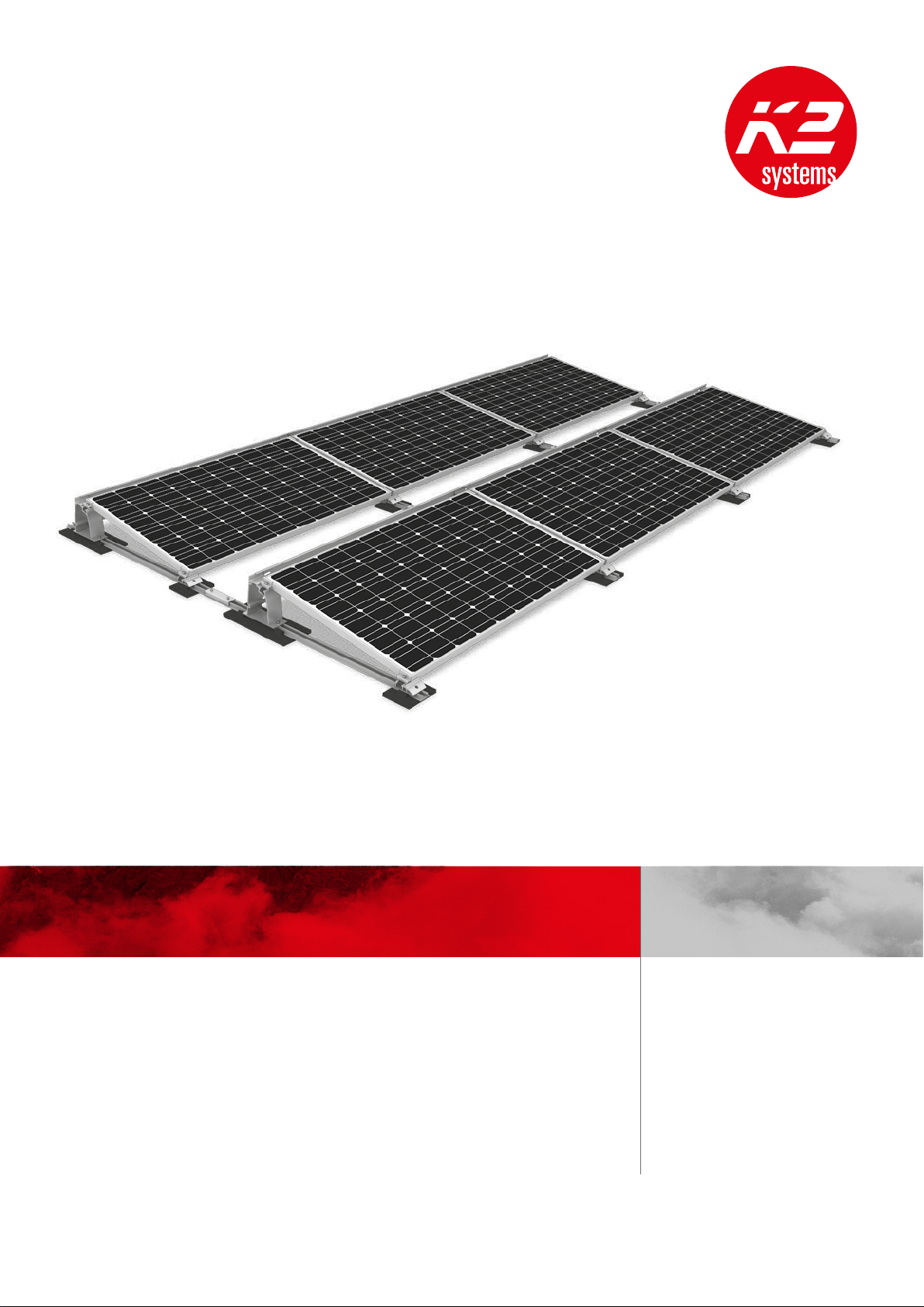
¬ This system can be used on all established flat roof constructions with a pressure resistant substrate and a
roof pitch of up to 5°. External influences that act on this system are only reflected in the design of the bal-
last to a limited degree. For instance, unevenness, thermal elongation, moss, water accumulation and ageing
of the sheeting cannot be considered, although these factors might also precipitate system displacement
under certain circumstances. We recommend you check whether the system requires additional mechanical
attachment, as the impact of these influences may be greater on slanted roofs. The inclination of the Dome
systems is 10°.
¬ Any structural-physical aspects are to be observed. In case of any doubts an expert adviser (i.e. structural
engineer) must be consulted.
¬ Prior to placing down the SpeedRail as a base rail, a protection layer shall be used between the roof covering
and the rail to avoid any damages to the roof covering. Place the Speedrail onto the protection layer without
penetrating the roof. The compatibility of the protection layer with the respective roof covering has to be
checked by the installer. The protection layer is not part of a part of the mounting system, but is strongly
recommended.
¬ The mounting rails and the protection mats/layer shall be clean and dry before installing.
¬ The roof covering shall be clean and level. If necessary any unevenness has to be levelled out or removed.
¬ The minimum distance to roof edges is 500 mm and 300 mm to all other obstructions (i.e. skylights, vents
or similar).
¬ At least 1 row of 3 modules must be installed consecutively in order to use this system.
¬ The module distance according to the planning specifications of K2 Systems must be adhered to.
¬ The K2 S-Dome System is suitable for modules with a frame height of 30 - 50 mm.
This system is not suitable for thin-film modules.
¬ Modules with widths between 1550 - 1700 mm and a width between 950 - 1100 mm can be used.
¬ Ensure a thermal separation (distance between module blocks) after a maximum of 13.50 m in the module
row direction and in the direction of the base rail. Thermal separation can be connected using the dome
block connector in order to increase ballast effectiveness. Separation distance: in the rail direction min. 50
mm max. 80 mm. If no block connector is installed: max. 500 mm. Recommendation: min. 180 mm in mo-
dule row direction for trouble-free installation of ballast adapter.
Please note: Additional ballast is required for separation distances exceeding 500 mm. In addition, the flow
of rainwater must not be hindered.
¬ It is essential to clarify, from the start, whether there is a module manufacturer‘s approval available for the
clamping on the short side of the installation system S- Dome S1000. You can obtain the approval list from
your customer consultant or at www.k2-systems.com.

Installation of S-Dome System 10 | 20
IN GENERAL:
(A)
(C)
(B)
III
SPACING WITH DOME BLOCK CONNECTOR:
(A) Module block in module direction: 13.5 m
(B) Module block in rail direction: 13.5 m
(C) Gap width along the base rail: min. 50 mm; max. 80 mm
III Gap width between module blocks in module row direction: 140 mm, 210 or 310 mm
II Distance to rail end:
(II.1) Fixed bearing side min. 50 mm
(II.2) Floating bearing side min. 100 mm
(II.3) Floating bearing side to adjacent components 140 mm
SPACING WITHOUT DOME BLOCK CONNECTOR:
(A) Module block in module direction: 13.5 m
(B) Module block in rail direction: 13.5 m
(C) Gap width along the base rail: min. 339 mm
(III) Gap width between module blocks in module row direction: min. 180 mm; max. module width
(II) Distance to rail end:
(II.3) with adjoining components min. 20 mm
E
E (1 : 5)
F
F (1 : 5)
II.3
II.2
(C)
Detailed image with
Dome block connector
II.1
III
Detailed image of gap width

POSITION SPEEDRAIL
INSTALL RAIL CONNECTORS
Prior to placing the SpeedRail as a base rail, insert a protec-
tion layer between the roof covering and the rail in order to
avoid any damages to the roof covering. With membrane
roofs the Aluminium-coated side shall face downwards. Place
the Speedrail onto the protection layer without penetrating
the roof. The protection must have to be placed under the
load bearing components Dome S1000 and Dome SD.
Position the protection mats and base rail according the re-
quirements of the array. The spacing between the mats/base
rails is determined by the module dimensions (module length
+ 20mm). ‚Connect‘ the K2SpeedRails to the protection
mats via the pre-cut WINGS.
The rail ends of the K2SpeedRails must not protrude the
protection mats.
Materials required: K2 SpeedRail, building protection mat
Dome 470x180x18 mm
Two SpeedRails are connected at the rail joint using a rail
connector. This locks the SpeedRails in the longitudinal
direction. Insert 2 M K2 slot nuts in the rail and turn 90°
clockwise to lock. Fasten rail connectors with two Bolts with
serrated under head M8. The connector should be between
the Dome S1000 and Dome SD.
If the rail lengths permit, the rail joint can also be positioned
directly below the Dome S1000 without a rail connector.
However, it must be ensured that the joint is between the
two fittings and under no circumstances directly at the
screw position.
Torque 14 Nm
Materials required: FlatConnector Set
1
of 9
2
of 9
11 | 20
Installation of S-Dome System
INSTALLATION OF S-DOME SYSTEM: STEP BY STEP

A
A (1 : 5)
E
E (1 : 5)
INSTALL BLOCK CONNECTOR CW IN RAIL
LONGITUDINAL DIRECTION
3a
of 9
Adjust thermal rail joint spacing of the two SpeedRails to
50mm up to 80 mm. Position the Block Connector CW
onto the two-speed rails. Recommended spacing between
the connector ends to the rail ends and adjacent compo-
nents such as Dome, SD Dome or Porter must be observed.
Fasten the connector through the bore hole with M8 screw
and MK2.
Tightening torque 16 Nm.
Insert pre-assembled screw set through the bore hole slot
to the speed rail, adjust the middle position and fasten.
The central position is located when the washer obscures
the two line marketings completely.
Tightening torque 10 Nm.
Using the right tightening torque ensures a small gap
remains between the washer and connector surface.
Mount each rail joint in the longitudinal direction of
a Dome Connector CW. The connector may only be
mounted in a roof tilt direction and not on „covings“ or
„ridges“. The connector must not be obstructed with
excessive ballast. During installation ensure that the screw
is loosely screwed in the bore hole.
Required material: K2 SpeedRail, K2 Dome block connec-
tor CW Set
A
min. 50
min. 50
max. 80
min. 100
A (1 : 10)
12 | 20
Installation of S-Dome System

A
A (1 : 5)
E
E (1 : 5)
INSTALL BLOCK CONNECTOR RW IN THE
MODULE ROW DIRECTION
3b
of 9
Adjust the thermal separation between the SpeedRails to
the correct distance. Block Connector RW allows a rail spa-
cing (axis to axis) of 180mm, 250mm or 350mm. Position
the Block Connector RW across the two Speed Rails with
the open side facing up so that they are perpendicular to
the SpeedRail. Fasten the connector to the SpeedRail in the
bore hole with the M8 screw and the MK2.
Tightening torque 16 Nm.
Insert pre-assembled screw set through the bore hole slot
in the other speed rail, adjust the middle position and bolt.
The central position is located when the washer obscures
the two line marketings completely.
Tightening torque 10 Nm.
Using the right tightening torque ensures a small gap
remains between the washer and connector surface.
Mount each four module rows with a Dome Connector
RW in the module row direction perpendicular to the Spee-
dRails. At least 2 connectors must be installed per module
array. The connector may only be mounted in a roof tilt
direction and not on „covings“ or „ridges“. The connec-
tor must not be obstructed with excessive ballast. During
installation ensure that the screw is loosely screwed in the
bore hole.
Required materials: K2 SpeedRail, K2 Dome block connec-
tor RW Set
A
180
250
350
A (1 : 5)
13 | 20
Installation of S-Dome System

Installation of S-Dome System 14 | 20
FIT DOME SD
Insert one M K2 slot nut in the rail and turn 90° clockwise
until it locks. Place the Dome SD onto the rail and align as
per the adjacent figure. The distance between Dome SD and
Dome S1000 is approximately equal to the module width.
Before fastening ensure care should be taken that the pro-
tection mat Scale 300x140x18 and its WINGS are under the
Dome SD and the rails at the array edges do not protrude.
Finally the Dome SD is loosely fastened with a bolt with
serrated under head.
Materials required: Dome SD, M K2, bolt with serrated
under head M8x20,, S8 locking washer, building protection
mat Dome SD 160x180x18 mm
5
of 9
Insert two M K2 slot nuts in the rail and turn 90° clockwise
until they lock. Thereafter, position the Dome S1000 on the
rail. Position the protection mat so that two WINGS are
under the Dome S1000. Only then fasten the Dome S1000
with two bolts with serrated under head M8x20.
Torque: 16 Nm
Materials required: Dome S1000, M K2, bolt with serrated
under head M8x20
FIT DOME S1000
4
of 9

6
of 9
K2 SpeedPorter Installation
Depending on ballast size, position each SpeedPorter with
the appropriate distance and insert the ballast.
Required material: K2 SpeedPorter
Ballasting with K2 Porter:
The L-Profiles are fastened to the rails with the screws and
M K2 slot nut included in the set. Torque: 16 Nm. The
spacing of the L-Profiles depends on the number of bricks
used. The Porters can be positioned both centrally to the
Dome 1000, or laterally to the middle Dome.
Warning: K2 Porters must be mounted so that all base
profiles within a module block are connected.
Materials required: K2 Porter, M K2, bolts with serrated
under head M8x20
BALLASTING THE SYSTEM
Weighted down with ballast using bricks or slabs. Please
follow the guidelines listed on the ballast weight table on
page 16.
Ballasting without additional item(s):
If only light ballasting up to 5 kg is required, insert one brick
directly into the hollow chamber of the Dome S1000.
Ballasting with K2 Short Porter:
The L-Profiles are fastened to the rails with the screws and
M K2 slot nut included in the set. Torque: 16 Nm. The
spacing of the L-Profiles depends on the amount of bricks
used
Materials required: K2 Short Porter, M K2, hexagon socket
countersunk head screw M8x20
15 | 20
Installation of S-Dome System

Ballast weight table
Ballast weight in kg
(Limit value in K2 Base)
Recommended
additional items
Recommended
brick dimensions
in cm
Max. no. of
bricks Installation recommendations
Up to approx. 5 kg
No additional
articles required
20x10x8
20x20x10
20x20x6
2
1
2
2 bricks in the cavity of the Dome S1000
1 bricks in the cavity of the Dome S1000
2 bricks in the cavity of the Dome S1000
Approx. 5 kg to approx.
40 kg
SpeedPorter Set
one side of the
dome
40x40x4
30x30x5
2
3
Where necessary, an additional 2 bricks
20x10x8 in Dome S1000
Approx. 5 kg to approx.
17.5 kg
K2 Short Porter
40x40x4
30x30x5
50x50x4
2
2
2
From approx. 40 kg K2 Porter
40x40x4
30x30x5
50x50x4
2
2
2
Approx. 40 kg to approx.
80 kg
SpeedPorter Set
both sides of the
dome
40x40x4
30x30x5
2
3
Where necessary, an additional 2 bricks
20x10x8 in Dome S1000
Table for bricks and slabs *
Type Weight in kg Dimensions (LxBxH) in cm
Paving bricks
2,2
3,5
4,5
5,4
7,2
10x10x10
20x10x8
20x10x10
20x20x6
20x20x8
Flagstones
(slabs)
14
19
22
40x40x4
40x40x5
50x50x4
Warning: Pay attention to module inclination when using Short Porter and Porter!
For ballast weights exceeding 100 kg, please consult a K2 technician.
We are happy to assist you with selecting the optimal ballast components once you the ballast size is determined.
* recommended values
16 | 20
Installation of S-Dome System

8
of 8
First, insert the M K2 slot nut into the nut of the Dome SD
and the Dome S1000 and turn 90° clockwise.
Screw the modules at the end of each row with module end
clamps, bolt with serrated under head M8 into the slot nuts.
If the module end and mid clamp set is supplied, fasten the
entire set in the groove.
Use two standard module middle clamps each between two
modules which are also fastened with bolts with serrated
under head M8 screws in the M K2 slot nuts.
Alternatively, XS mid clamps can be used.
However, longer screws must be used in this case.
The length of the cylinder screw with serrated flange is defi-
ned as module frame thickness + 15 mm when using the XS
middle clamp.
Torque: 14 Nm.
Materials required: Module end/ mid clamp Set
FASTEN MODULE
POSITION MODULE AND FASTEN DOME
SD
The modules are laid horizontally, in the centre of two
Dome D1000s. The specially affixed bars serve as the stop.
Thereafter, the module is positioned on two Dome SDs.
The only loosely fastened Dome SD together with the
protection mat SD 160x180x18 mm are pushed towards
and against the module and then fastened. Before fastening
ensure that the WINGS of the protection mat are under the
Dome SD and the rails at the array edges do not protrude.
Torque: 16 Nm.
Attention: Only modules approved for corner clam-
ping may be used, see point „GENERAL SAFETY IN-
FORMATION“ on page 9. Please take care not to cover
any drainage holes in modules, otherwise potential
condensation cannot run off.
7
of 9
17 | 20
Installation of S-Dome System

INSTALL THE WINDBREAKER
First position the upper fold of the symmetrical windbreaker
on the bar of the Dome S1000. The foiled surface must face
outwards. We recommend removing the foil once installati-
on is completed.
Align the windbreaker against the module edge and fasten
with the allen bolt M8x16 with the aid of the elongated
holes and washers in the screw channel.
When two windbreakers overlap, position the plates in such
a way that the screws can be screwed in the screw channel
with the aid of the elongated holes. For this a washer must
be used.
It must be ensured that the last windbreakers in a row do
not project over the Dome S1000.
Torque 16 Nm
Materials required: Dome S1000 Windbreaker, allen bolt
M8x16, 8.4 x 30 x 1.5 washer
9
of 9
18 | 20
Installation of S-Dome System

Installation of S-Dome System 19 | 20
THANK YOU FOR CHOOSING A K2 MOUNTING SYSTEM.
Systems from K2 Systems are quick and easy to install. We hope these instructions have helped.
Please contact us if you have any questions or suggestions for improvements.
https://k2-systems.com/en/contact
Our General Terms of Business apply. Please refer to:
https://k2-systems.com/en/company/terms-of-delivery
Ready!

Installation of S-Dome | GB12 | 1016 | Subject to change.
Product illustrations are exemplary and my differ from the original.
Mounting systems for solar technology
SERVICE-HOTLINE
+49 (0)7159 42059-0
Other manuals for S-DOME SYSTEM
1
Table of contents
Popular Inverter manuals by other brands

InfiniSolar
InfiniSolar Hybrid 1kW user manual

Mastervolt
Mastervolt WHISPER 9.5 ULTRA installation manual

Midian Electronics
Midian Electronics MOT-TVS-2-PRO instructions

Omnik
Omnik Omniksol-2k-TL3-S user manual

SEW-Eurodrive
SEW-Eurodrive MOVIDRIVE modular Compact operating instructions

Generac Power Systems
Generac Power Systems 2.4L owner's manual