KAESER TD 61 User manual

i
Refrigeration Dryer
Model: TD 61
Part No.: 1 7987.10010
serial No.: Al-S-12
lndex: 060909
GL-Nr: BA-TD61 - 1 '7947 1C'-':-::
KAESER KOMPRESSOREN GMbH
D-96410 Coburg ' Postfach 2143 ' Tel (09561)640-0 . Fax. (09561) 640 - 130

((
!Ve hereby declare that the machine/unit of
iype: compressed ail re liigeration dryer part number: 1. i9e 1.1c010
make: Keeser serial number: 61SQ 2
TD 61
:onforms, in the specification supplied by us, to the tollowing relevant conditions,
.:: pa rtic u lar:
D ilect i,,'e 1-or mrchinerr
Declaration of ConformitY
within the meaning of machinery directive Bgi392/EU, appendix ll A
Directive for lori, r'cltlge
D;rcciivc cor:;cniiirg e1e--i; onlgnetic conrpatrbilitl
:: air',ronised standards appl ied, i n particu lar:
Refr i-ger:t'o r rr:'t ,n.: : 'I jr.f - J:.r'-\ rc ri:cn:c"r'
S afety of nrach lner,
!r'. r9-1: Safety of mrchinery - saiety disiances
Salety of n.rr.chinery - electrical equipment
l\ -i i108 I ?: Eleclromasnetic compatibiiity - radio interfere nce lf:rnsnisslon
E.lectromagnetic compatibility r':rdio interference suppression
llation al technical standards and specifications applied, in particular:
l:: .:: r re nt safe[v act
:,- - ::::"'nt slfety act regulatior,s
'' r - ,,,, l.:liseration units, helt pumps and cooLing srsie nr,.
-10.i1.199.1
Dair t.l-.. r ..----. .,I
cesc.:ris:-r.r,rr_ ::.-..j a..r ii3.:-.r ip -',,' .n! T .rf;s l.:lrs,i.
:a a,::-::3 232
iSl-lc:,r.: l- l:?trai:::
.::.,.;N:SSOREN GMbH
'.- - ,'2a DS4150Ccbur! Tel.: (0 95 61)6rGa
F3,\i (0 95 : l) c-a i:-1
T x: 6a3 2 a-1 , '::.

Table of Contents
'lechnical
1.1
1.2
1.3
1.4
1.5
'1 .6
1.7
1.8
1.9
1.10
Srafety Regulations ....
Spare Parts
Environmental proieclicn
General
3.1
3.2
4 Transport
Explanation of Symbols and References
General Safety lnstructions
Accident Prevention Fegulations _ Germany, U\,A/ 20.0, ,,Fefrigeration plants,
Heat Pumps and Refrigeration S./,siems,, 0/BG 2Or
General References .. . .. .
Chapter page
. 1_1
1-1
t-l
1-1
1-1
1-2
1-2
1-2
1-2
1*2
2*3
2-3
2- 4
3-5
3-5
3,5
2.1
23
2.4
2.5
2.6
4.1
4.2
4.3
lnstallation
4-6
4-6
4-6
5*7
5-7
5-7
5-B
5-B
5-8
5*9
5 - 1C
5 - 10
6 - 11
6 - 11
6 - 11
6 - i2
Transport Instructions .......
Packaging
TemporaryStorage ..,..,..
Construction and Operation
5.1
5.2
5.3
5.4
5.4. 1
5.4.2
c,4. -l
5.6
i)
6.1
6.2
6.3

Table of Contents
6.4
6.5
7.1
7.2
7.3
Electrical Connecirc:r
Vollless Contacis 6 - 12
6 - 13
P utting into Service
Poirts to be Nole: :;. - -: : -: - _:
Points to be Observec c-,:-= S,.,
Operational Reacin:ss . .
::3 Service .....
::: ng On .....,.
7*14
7 - 15
8 Operation ..
8.1 Control Panel .. ,.. 8_16
8.2 Switch jng on the F:.- :=-z-. :- :--, =: 8 _ 17
8.3 Switching off rhe F=.-:=-:::- l-,:. . ........8_18
8.4 Fault Finding .. .,... g_l8
8.4.1 Water in the cc-::-:ss:: :.:..::::r: . ... . ,. . . B _ 18
8.4.2 High press!:a :s::: . : :-= .=,-:::a: cn dryer ... ...... B_ 18
3.4.3 High cornprsss:: : - :::-: ... s _ j9
3..1.4 Thecontrol la-:: -*-_:::: -:::Klfguish inpadial load running orwth
10
11
no load .....
8.4.5 Red LED cn i-: :l:-:::
Maintenance
-: -s :; flas hes
9.1 lu'laintenance ,r - =:
I 1,1 Functional cie:, :, :-:
9.1.2 Functional che: i :,:-:
9.1 .3 Functional chec.i :,:-:
9.1.4 Functional chea,: :, :-=
9.1 .5 Cleaning the rei:::.:-:
9.1.6 General checks .
9.1 .7 Cleaning the ECC - I - :
9. 1.8 C eaning the Dia:-':;-
Spare Parts and After Sajes Seruice
ru.r 5e.vce Pals d-- -,-. --:. ::--j
Appendix
'1 1 ,'1 ELecirical Diagrar:
11 .2 Maintenance Scne: - a
B - 19
B - 19
9-20
9-20
9-20
I - 21
I - 21
I - 21
9-22
9-22
10-26
1A - 27
11 - 28
I I - 23
Chapler - Page
.. " t.*

Technical Specification
'1 .1
Technical Specif ication
Ref rigeration Dryer
t\4odel .,
Cooling airvolume .......
Condensate volume under nominal conditions* . .
Weight..
Dlagrams:
Dimensional diagram .
By-pass pipe
P & lfiow diagram TKTTDS1
(Pipe and instrument flow diagram)
Electricaldiagram. ......., SKT.TD61
*See chapter 1.3 for norninal conditions.
1.2
1 .3 Compressed Air System
Flow volume
relative to an ambient temperature of 25
compressor gauge pressure oi 7 bar.
Pressureloss........
Pressure dewpolnt
at an ambient temperature of 25'C, compressed
gauge working pressure of 7 bar.
Ma-ximum gauge working pressure .
1.4 Refrigerant System
Refrjgerant
Quantity.
.,.... TD 61
. .... .. 3soo m3/h
.......1sso g/h
..... .. . 2s1 kg
... T 9007.1
. .203179.A
-0795i00016
- 0695/00070
....6,2 m3/min
'C, 9BO mbar atmospherlc pressure anC
...... 0,12 bar
air lnlei ten'tperature of 35'C a-:
Sound Pressure Level
Operatlonal state ol the refrigera on dryer:
rated pressure and rated air f ow.
Measurement conditions:
free field measurement
Sound pressure level d ata:
measurement to DIN 45635 (noise measurement on machines, compressors) at
. 1 m distance
. 1.6 m heig ht
Sound pressure level less than 70 dB (A).
rb oar
' 5 (a
1-1
"t i*
--,,!.: i"f i

11
aTechnical SPecification
Permlssible gauge v/orklng press:rre '
lnstallation Conditions
Vax. heiqht above se*'a." ':-. : ,-"
of installation
I'l in. ambient temPeralure .
Max. ambient temPeratr re .
**other heights permiss ir'e c: \'aier ccnsultallon wiih the
25 bar
{E
1000 m
,..5 'c
..43 "c
manufacturerl
1.6 Connection Fittings
Compressed air oui e: . -s :: ::::aC)
Condensate drajn c::^e::':- ^cse ccnnection)
Connections for cc:i: r3s::: 3'
pressu'e d'fie'er: z ' :=: --?-:-'
Se'vice colnecic-: i:-'::, - .: 'i'
Electrical Connection
N4ajns vo lage . .
Freq uency
Power consumPi c-'
l,4ax jmum powef a:'s--:::-
Maxlmum rated c L:'- -:
Mar. ma,cs'us ^g ;:,'::"--- I jis
Power supply c3: e - :': l l:i -i:l'--
(CU multicore cac ie
lrsLtation c dss rc:-:'j l3: -;: :-: ::-e
* under nominal ca^:::-s ::; :-:::'r i 3
Settings
Satety pressure sviitch irefiiE 2 '2 nt )
switching Poinl iiii.sr
Thermostat
'egulates oie5s-'= -i: :: -:::
switchlng Pcint icr ''c,i -::::
hgh PressJ'. D+"':- -; .^-:-::
Designation
The namepLate of the cryer is caa:3: :- :-' :::
1O lorthe.r.uslrattor c' Ire -a- : : ::+
Dimensional Diagram
(see next page)
... 230 v |10 % L1/N/PE
.... 50 Hz
.. 1000 w
..'1400 w
... 6,5 A
....16 A
3x1,5 mm2
..1P54
..25 bar
ca. 3 "C
ca. 12 'C
....G1112
.,... DN 10
... 2x G 1/4
2x 7/16 UNF
1.7
1.8
1.9
: .i 0
1-2

,.-
C
:,1
-'1I
-i
:i
.: :_-
"3
3",
EE
.t:
;l
:^
;l;
fl-
9l 3
3i:
,-)l:
.A
;t
; lg
1+
.g
i:
a
(t,
Lr)
rl
F
0s?
Ei
*^r::1,

3010
2A
50
r----
tl
ll
na: i.n s:iew-ir le ri i:
PN 16 bor
[i 5'1/61
€-olrl C!rc h
!,'Cer,"i;e r
1995 | r"; i€,tLo
By poss R11/2
:!l.:.r".-)ir
20:179 0 e

Safety
2 Safety Regulations
Bead thisseryice mal!a. :..=', : =-:::-.:-.;: l:_::-:-_,' r:ierel:es c:for€ outiing this
refrigeration dryer intc c:a''.'.a- =--. =:':.2 az.-, -a:,-. a-. -a:i:a:atJ: of ihe unit.
2.1 Explanation of Symbcls and References
This symbol is ;i3ced befsre all :€ierences to salety where danger to
liie and lirnb cai occui during y;c:k. lt is especially irnportant that
lhese rules are cbseryed and that extreme care is taken in these
cases. For their own protection, intorm all other users about these
safety rules- Observe general safety and accident prevention regula-
tions as well as the satety rules laid down in this service manual.
This symbol is placed by text to which considerable attention must be
paid so that recommendations, regulations, relerences and correci se-
quence of work are adhered to and that damage to and/or destruction
ot the refrigerant dryer and/or other equipment is prevented.
This symbol deslgnates measures taken to ensure environmental care.
Thls symbol indicates operations and actions to be carried out bv the
user
This bullet ideniilies listings.
2.2 General Safety Instructions
European Standards (EN) must be complied with during installation, operation, rnainten-
ance and repair of the refrigeration dryer.
valid national safety regulations must be complied with for those corresponding European
Standards that are not yet incorporated into naiional legislaiion.
Users of refrigeration dryers located outside the jurisdiction of European Standards are
obliged to comply with the safety and accident prevention regulations concernirrg the re-
frigeratlon dryer that are valid in the country of use. lf necessary, corresponding measures
must be taken to ensure compliance with national legislation before the refrigeration dryer
is put into operation.
2.3 Accident Prevention Regulations - Germany, UW 20.0, ,,Refrigeration
Plants, Heat Pumps and Befrigeration Systems,, (VBG 20)
We refer especlally to:
Paragraph 16 "lnstallation of relrigeration plants,'
Paragraph l9 "lnstructions, operatlon, maintenance',
Paragraph 20 "lnstructions to operators"
lr-r l
L:u
tL
1_

Cl
Safety
2
2.1
Safety Regulations
Read thls service nranua carefuliy and observe ali cautionary references before pu ing this
refrigeration dryer nto operation and before carry ng out any maintenance on the unit.
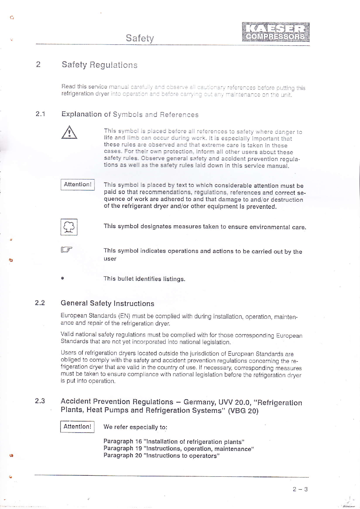
Explanation of Symbols and Beferences
This symbol is placed before all references to safety where danger to
life and limb can occur during vrork. It is especially irnpodant that
these rules are observed and lhat extreme care is taken in th"se
cases. For their own protection, inform all other users about these
safety rules. Observe general safety and accident prevention regu!a-
tions as vie I as the safety rules laid down in this service manual.
This synrbol is placed by texi to v,/hich considerable attention musl be
pajC so that recom mendations, regulations, reterences and correct se-
quence of !,,,ork are edhered to and that damage to and/or destruction
ol the refrigerant dryer andior other equipment is preventec!.
This s):bcl designates measures taken to ensure environmental care.
This s/rbcl iraicaies cperations and actions to be carried out bv the
USET
This b u llei ice:::3s.;s:::,Es.
General Safety In stru ctic r'ts
European Standards iEiil :--.:.:::-: :: ,,.-:,--.- -s:: atc:. aperaticn, rnajnten-
a'tce aro .eoa:r or tr r '.'- :.:--: - - -.:
ValiC natlonal safety regu at.-s -,:: -a _--- .'-.,::,:l.:-:se.ol'espondtng European
Standards thai are not ye\i-ia:-.a-='-, --.: -: a^z .g s a:ron
Usersof relrigeration dryers:caa:a: : _:: :: :-: _'sl.icI r::uropean Standards ate
obligedtocomplywithihesaie:i."..-::.-'.....=....t.'guetionsconcernirLgthere-
frigeration dryer that are vai d ti- i.-.: a:,-'-, : ,.; , "e--:ssary, corresponding n,"uaur"a
must be taken to ensure ccric ar-t: ,.. :- -:::-: :J s ai cn beiore the refrlgeiation drye r
is put into operation.
,Accident Prevention Regulations - Germany, UVV 20.0, ,,Ref rigeration
Plants, Heat Pumps and Refrigeration Systems,, (VBG 20)
We refer especially to:
Paragraph 16 "lnstallation ol refrigeration plants"
Paragraph l9 "lnstructions, operalion, maintenance',
Paragrap6 20 "lnstructions lo operators"
tr
[3
a.J
Attentionl
2-3

a
Safety
G en eral
A
2.tl References
Work on power driven systems may only be carried out by trainecl or
instructed personnel or by specialised personnel.
Work on the electrical equipment ol the relrigeralion dryer may only be
carried out by a qualified electrician or trained personnel undojr ihe
supervision of a qualitied electrician according to electrotechnical
provis io n s.
The refrlgeration dryer contains live components.
Carry out the followlng measures in the sequence shown beiore at_
temptlng any \york on the electrical system:
1. Switch off ali phases.
2. Ensure tlte unit cannot be switched on again.
3. Check that no voltage is present.
The refrigeration dryer contains syslems subject to high pressures.
Before any maintenance work is carried out, vent and shut otf the pres_
su re lines.
Escaping compressed air andr,or escaping refrigerant can ceuse irjury
and damage to equipment.
The instructions contained jn lhe information Ieaflet ZH 1i409.'\4erlc
blattes r.iber den Umgang mit FCKW" (lnformation Leallet Concerr:ing
the Handling of CFC Gas) must be observed when dealing vrith escaf_
ing refrigerant!
Do not allow the relrigeranl in the refrigeration
the atmosphere. Always use suitabie systems
lrigerant when carryinq oul maintenance work
culation system.
Dispose of unusable reJrigerant according to
system to escape into
d esigned to eKtract re-
on the refrigerant cir-
reg ulationsl
The warranty is invalidaled il moditjcations are carried out v/ilhoul
previous consultation with and the consent of KAESEH.
2.5
2.6
Spare Parts
The use of KAESEF, :r g ^a :a::
ation dryer.
Environmental Protection
Condensale d ra inag e
Condensate accumuiaiing during the d./jng oi compressed air n]ust
be drained into a special dispcsal canistef and then disposed ol ac_
cordin g to environmental ;eguiations.
Operational and repair materiais, consumable parts
Dispose of all used materials and consumable pads accumulating dur-
ing operation, mainlenance and repair of the i-efrigeration dryer ac_
cording to environmental care regulations.
c'ffiffi'
2-tl

aGeneral
.1 General
3.2
The service manual must always be available for use at the relriger-
ation dryer's place of installation.
.1. ICorrect use
The refrigeratjon dryer ls intenced scleiy ior drying compressed ajr.
Any other use outside of thls purpcse rs considered lncorrect' The manufacturer cannoi
ac6ept llability for any damage causeo cy such incorrect use; the user alone is liable for
any risks incurred.
Coirect use also encompasses ccnpL:ance with the lnstailation, removal' commissioning'
operational and maintenance ccrc;::cns laid down by the rnanufacturet
Copyright
'lhecopyrightofthissel',lce'::anua,isthepropertyofthefirmofKAESERKO[''1PRES-
SOREN.'Tliis service manuai ;s inlerced for operating personnel' maintenance personnel
and supervisory perscnnel -se :nly lt contains instructions and.technical diagrams that
may not be "opiad "ilh.r- :c-:'etely cr parily, distributed or €val.uated by unauthorised
persons for the purpcse 3: :.:-3€::'cl c:' djvulged to any other third party
35
ii.

TransPort
4
4.1
TransPort
TransPod lnstructions
i AGt';ll under no circumstances lift the relrigeration dryer with the com-
I ^"""""" 1 ir""."a "i, inr"i'"tii tulr"t "onnecti6ns or lay the reirigeration dryer
on its side
Serious damage can lesult lrom such treatment of the relrigeration
dryer.
To prevent damage to the.p,anelling ol t1:,1?IiS"t'tion dryer always
transport with a tiolley' a lift truck or a forklift truck'
Never drive directly underneath and then lift the refrigeration dryer'
r Always mount the reir gerai cn cryer on a sultaole transporting medium (pallet or
wooden basel o.:- 19 I/a-sc' i
ll a litting appliance is used to transport,the l"l]'"S-"lil:: dryer' take
care thai no side forces are exerted on the cover panels'
Packaging
The refrigeration dryer is loaded onto a wooden pallet and is protecteil by a carton o{
corrugated cardboard
Temporary Storage
Slore the refrigeration dryer in an enclosed space' regarclless of whether it is pacl<aged or
not.
rhe storage temperature should notfall below -25'C and not rise above 60'C
Att""ti";il Belore putting into operation' wait untilthe temperature ot the refriger-
^""""-" 1 urion owut hjs adapied to the ambient temperature'
4.2
4-6

5
5.1
Construction and 0Peraiion
Construction and OPeration
llems referred to ln ( )ccrres.crc //lth ihe ltems in the Pipe and lnsirument Flow Dlaqrafir
(see chapter 5.6).
Construction
The main component oi lne 'ei: !ef3i cn dryer comprises a combined heai exchanger
(heat transmitter) lt ccnsisis :: i:€ ''ic iollcvi ng rnair groups:
1st. stage: air to air heal exa'3-iei ri )
2nd. stage: air to refrigeral: 'er: 3xchanger (2)
The refrigerant circulatrcl s a-::;'atlca Ly regu ated \!lth a thermostat (13) A condensate
sefaratlrig system (3) s : i.l r- sel. es !!lih the heat exchanger
A safeiy pressure s!!::r .9 s'::C n ihe refrigerant circulatiotr sysiem as a protection
against excessive Pf ess-'€
A theimal overloac s,.,:a^ :'::::is lie refrigerant compressor (1 1) agalnst current over-
loads and hig h terPe'a:-'es
Functional DescriPtion
The cooling aclicn .i i-e 'e:::erallcn dryer causes the condensatlon and subsequent sep-
aration of the hLlnLd ::::3:i ci:le ccmpressed air'
The wartn cornpress€l :' :; : c'.r irum dity enterlng the un i is rnitlally cooled in the alr to
uirl.,"ut.r"nu..g.r i1 ::':-g- ::at e^cnange with the cooLed compressed air leaving the
unit.
FLrnher coollng oc.r-'s - ::e a r:o reirlgerant heat exchanger (2)' connected ln serres wilh
the air to air heai €xa:?.::=i iiiJUgn th6 action of expanding, gassing refrigerant This ac'
tion causes the hlr : a.-a".."',". cf the coinpressed air to condense out when the pres'
sure dewpoint s !rtr:':-:.
The condensate se:a'ai:' 3l ltrnnected in series' separates the condensed watcr and oll
droplets, togelheI Yi i- ::3:s. : r parircLes, from the compressed air' This condensate is
.emoved ''on t-o -rr:i- -- :- i.lo'al'c cocdensdle draln (5r'
The dried compress:: 3: s iler rewarmed by flowing through the air to alr heat ex
changer (1) befcre aa' :! 1:3 iairlEeration dryet
TherefrigerantCoT].3.-SS:i.i1]]]SSw]tChedoftbyatherrnostallltherefr]geratjon.]er.3l]]
sinks ani swiichei .^ ag: i ,',Ten lhe demand iises Considerable savings in energ\' :::
posslble with this c'-. p e cf cterallcn'
Ref rigerant Circulaiion
The refrigerani LrseC ll :ie reirigeration dryer is fecl round a hermet ca lli I c'e: : ':- :: - -
ay.1". tiut changes lre iiqurdLr gaseous state uslng correspcndlnq ietli 'a :-:
The reirigerant con'pressor (1 1) draws in.gaseous refrigerant anr c't-i'':::: - t -..
densatjon pressure lle ccmpiessed refrigerant gas arrives at lhe 'elr -:l''a:: :-'' =i : l
uiu thu "pl,u..ul'u jlne . -fhe relrigerant ls liqueflecl in ihe condenser b"' :--= :":::': :' :r
h eat.
The refrigerant is expanded by the capllLary tr-llre (7) ircn' c3i.rc3nsa: c:- :':s3-': :i -l3s-
.ing pr"irrr" and iniecled inlt the air to reirigerani iieai :\':::g3' t l -':'::^:.1i -^
s n! of the refrigerant occurs through neal extiaclicn :rci'i:re -'i :::-'i;sstl alr etl.i rq
:i'e dryer.
A2

Construction and OPeration
5.4
5.4.1
The gaseous refrigerant ls then fed back into the refrlgerant compressor (1 1) agalrr'
ECO-DRAIN
Functional PrinciPle
Items referred to in ( ) refer to the items in the lollowing {igures
. The accumuLating condensaie is colLected ln the chamber (2) after passing ihrough
the inlet openinq (1). The diaphragm valve (4) ls ciosed
. A capacitlve senscr (3) continuously reglsters the liquid levei and passes a slgna to
the electronlc ccntrol (7) as soon as the chamber is full' The pilot valve is activated
and the diaphragm vaive ('1) opens the outlet line (5) when the ECo-DRAIN is
empty, the out et lire is closed again before compressed air can escape'
1 2 34 5
1 lnlet aPening
2 Callecta(
3 Level deteclcl
4 Diaphragm vai'e
c If a iault occu:s a : : :- :=:
fault. T\e rec :-: : - : -: i
5 Uullet ltne
6 hotsing
7 Eleclranic canlral
8 Light-emifting diode (red)
:^a . a.!'e oycles cn and ofi continL-lously lo c ear the
5.4.2 ln dlcation oJ OPeration3l Stalus
Theoperationalsia:;sa':-:::-::-:::::-:-:-:::::::':-:'=:-il33li'r6r'truS-
lnq ot tne LUU - L r-- . .
1 LED on perTnane-: ':
nor-al FCO-;:^'. .::':: : '
2 LED exljnguishes :o: a sicl ::' ::
ECO-DRAIN cis.'a:g e :'/3 e
3 LED flashing coni r-.tously:
fault, overloaC
5-8

a
Construction and Operation
5.4.3 Funclional check
Check the function of the ECO-DFAIN by pressing the TEST
DFAIN will switch to the discnarge mode at a rhy,thm of 2 to 3
flashes at the same rh!4hm.
pushbutton (9). The ECO-
seconds. The LED (8)
I
IOperational status - itght enitting diade (red)
TEST pushbutton /coniensale drain)
5-9

Construction and Operation
5.5 Component ldentif ication
Positlon numbers n ( ) ccriespond lc those in the Pipe and Instrument Flow Diagram.
(P&lFlowDiaqram).
?.,
1 Compressei e' ^ .:
2 Cantral cubicte
3 Refigerant corla'9ss:- :
4 Heat exchanget i1). 2.
5 Condensate secaia:o.'3,
6 Compressed ar,' oL lre:
I S;ley p/essu re s,uitch (9)
a F::ler dryet (8)
-. Carillary tube (7)
' - 3eftigenni iiqueliet i1A)
" icriensare ECA DBAIN (5)
'a -l? 1 io,.e
5.6 Pipe and lnstrument Florv Diagram (P & I Flow Diagram)
(see following paq es)
5,10

lil
.-i_\ i i
- i r. I
''--- ,.. i
.:. ::
.:.
j.3-
- - lt: ,
' 't]* a,)
- l-1 Lr ri
i""-
] 5.."
t_.
i
rL
ir,
ii.
ri
ll
:
l-, 1'
' .,1
:
ill . r-
1-.-:l'-
:
i r.l
.i.
illl
':.
{-
e
i
ii
o ll
!
l
1-
l
_l
a\

'.!I
j:i
l:- l
l.:i
l:l
i;l
=
:a
-_l
i
2 c"
1, -o .:
.:",- r
=
.=
C!
u.t
t--.1
t,
l
a
il
I
::

,i
lnstallation
6
6.1
lnstallation
Conditions of lnstallation
The refrigeration dryer musi ce lrs:alled in a dry and dust free space. To ensure adequate
room for the maintenance oi:ne re:ficeration dryer, the minimum distances quoted must
be complied with (see icl c,i;inc skelch).
lnstall the dryer on an evef ila: sur;ace. Special foundaiions for the installation oi the refrig,
eration dryer are not necessai.,,.
See chapter 1.5 for the i:re a|l]bient temperature and maximum height of the place of in-
staJlation.
To ensure pertect inlet and exhaust ventilation o{ the retrigeration
dryer the minimum measurements quoted lor the free space at the
cooling air inlet and exhaust may not be undercut.
l\4easurements s.-a.r-:-: - - --- i::: t3 r,easi)tentents
A Caoling air i' e:
B Caalinq air aL:..:
The tiiting of ic;e! and or exhaust air ducting without previous con-
su'tation iriti the i<AESER Ccr:tpany is not perrnined.
6.11 Compressed Air Connection
Take care during installatjon ihat no strain. pressure or bendinq lorces
are acting upon the compressed air conneclions.
I
o
The refrigeration di,/er .s ai,rec -aza: ':- :=:t-.'. a-.
Shut-ofl valves:
A All power driven systems must be equipped with a
lor all forms of energy leed. the operation of which
start and stop of the energy supply to the system.
main stop system
determines lhe
l-lEr. --
6 - 11
Table of contents
Other KAESER Dryer manuals