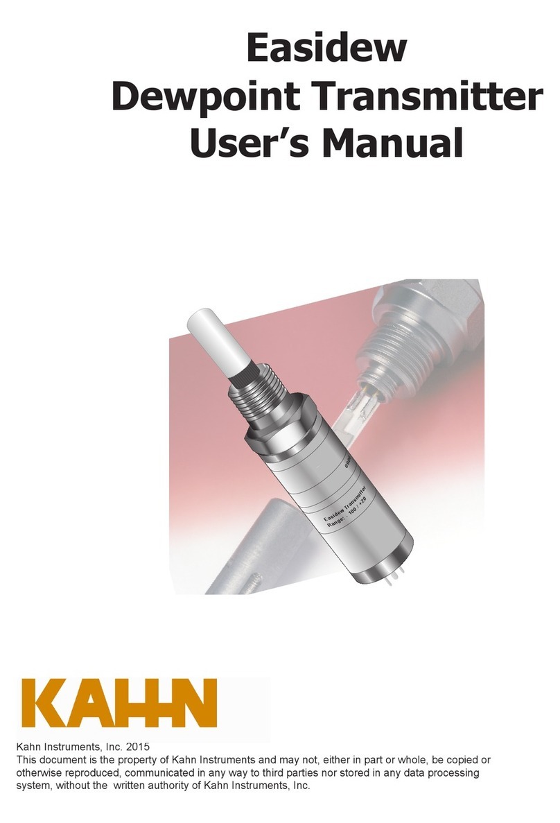
Kahn Easidew PRO XP User manual

Easidew PRO XP
Moisture Transmitter
User’s Manual
Kahn Instruments, Inc. 2016
This document is the property of Kahn Instruments and may not, either in part or whole, be copied or
otherwise reproduced, communicated in any way to third parties nor stored in any data processing
system, without the written authority of Kahn Instruments, Inc.

© 2016 Kahn Instruments
This document is the property of Kahn Instruments , Inc. and may not be copied or
otherwise reproduced, communicated in any way to third parties, nor stored in any Data
Processing System without the express written authorization of Kahn Instruments , Inc.
Easidew PRO XP
For Kahn Instruments' contact information please go to
www.kahn.com

Easidew PRO XP User’s Manual
iii 97442 Issue 2.5, January 2016
1 INTRODUCTION ................................................................................................1
1.1 Features ............................................................................................................ 1
2 INSTALLATION ..................................................................................................2
2.1 Unpacking the Instrument................................................................................... 2
2.1.1 Wall Mounting .............................................................................................. 3
2.1.2 Pipe Mounting............................................................................................... 5
2.2 Gas Media Process Connection ........................................................................... 6
2.3 Liquid Media Process Connection ......................................................................... 7
2.3.1 Sample Block (Optional) ............................................................................... 8
2.4 Electrical Schematic............................................................................................ 9
2.4.1 Easidew PRO XP EX1 (Non-Display)................................................................ 9
2.4.2 Easidew PRO XP EX2 (Display)....................................................................... 9
2.4.3 Electrical Boundaries ................................................................................... 10
2.5 Preparation of the Sensor Cable ........................................................................ 11
2.5.1 Terminal Block Connection - Easidew PRO XP EX1 (Non-Display) .................... 11
2.5.2 Terminal Block Connection - Easidew PRO XP EX2 (Display) ........................... 12
3 OPERATION ....................................................................................................14
3.1 MeasurementandConguration ........................................................................ 14
3.2 Sampling Hints................................................................................................. 15
4 MAINTENANCE ................................................................................................16
4.1 Calibration ....................................................................................................... 16
4.2 Sensor Guard Replacement ............................................................................... 16
4.3 Display Replacement..........................................................................................17
4.4 O-Ring Replacement..........................................................................................18
Contents
Safety ................................................................................................................................ v
Electrical Safety ........................................................................................................... v
Hazardous Area Safety ................................................................................................vii
Pressure Safety.......................................................................................................... viii
Toxic Materials ........................................................................................................... viii
Repair and Maintenance ............................................................................................. viii
Calibration................................................................................................................. viii
Safety Conformity ...................................................................................................... viii
Abbreviations......................................................................................................................ix

Easidew PRO XP User’s Manual
Kahn Instruments iv
Figures
Figure 1 Sensor Cap Removal...................................................................................2
Figure 2 Dimensions Easidew PRO XP EX1 (Non-Display) - Wall Mounting....................3
Figure 3 Dimensions Easidew PRO XP EX2 (Display) - Wall Mounting...........................4
Figure 4 Transmitter Mounting - Pipe or Duct.............................................................5
Figure 5 Dimensions Easidew PRO XP EX1 (Non-Display) - Pipe or Duct .....................5
Figure 6 Dimensions Easidew PRO XP EX2 (Display) - Pipe or Duct ............................5
Figure 7 Transmitter Direct Mounting ........................................................................6
Figure 8 Transmitter Mounting - Sample Block ...........................................................8
Figure 9 Outline Dimensions - Sample Block ..............................................................8
Figure 10 Electrical Schematic - Easidew PRO XP EX1 (Non-Display) .............................9
Figure 11 Electrical Schematic
- Easidew PRO XP EX2 (Display) ..................................10
Figure 12 Maximum Load of Easidew PRO XP - Including Cable Resistance.................10
Figure 13 Wire and Crimp Details .............................................................................11
Figure 14 Terminal Block Connection - Easidew PRO XP EX1 (Non-Display) .................11
Figure 15 Set Screw ...............................................................................................12
Figure 16 Terminal Block Mounting - Easidew PRO XP EX2 (Display) ...........................12
Figure 17 Set Screw ...............................................................................................13
Figure 18 Indication of Dead Space ..........................................................................15
Figure 19 Replacement of Sensor Guard ...................................................................16
Appendices
AppendixA TechnicalSpecications..............................................................................20
AppendixB HazardousAreaCertication ......................................................................23
B.1 Product Standards .......................................................................23
B.2 ProductCerication......................................................................23
B.3 GlobalCerticates/Approvals ........................................................24
B.4 Special Conditions........................................................................24
B.5 Maintenance and Installation........................................................ 24
Appendix C EC Declaration of Conformity......................................................................26
Appendix D Fully Programmable Loop Powered 4-Digit LED Display Meter ....................... 28
D.1 Display Meter Parameter Limits..................................................... 28
D.2 Display Meter Operating Range..................................................... 28
D.3 Display Meter View ...................................................................... 28
D.4 Re-CongurationSteps.................................................................29
D.5 Moisture Scaling Label .................................................................30
D.6 TechnicalSpecications-EX2LEDDisplay.....................................31

Easidew PRO XP User’s Manual
Kahn Instruments v
Safety
The manufacturer has designed this equipment to be safe when operated using the procedures
detailed in this manual. The user must not use this equipment for any other purpose than that
stated. Do not apply values greater than the maximum value stated.
This manual contains operating and safety instructions, which must be followed to insure the safe
operation and to maintain the equipment in a safe condition. The safety instructions are either
warnings or cautions issued to protect the user and the equipment from injury or damage. Use
qualiedpersonnelandgoodengineeringpracticeforallproceduresinthismanual.
Where this symbol appears in the following sections it is used
to indicate areas where potentially hazardous operations need
to be carried out and where particular attention to personal and
personnel safety must be observed.
Electrical Safety
WARNING:
During the installation of this product insure that all applicable
national and local electrical safety regulations are observed.
WARNING:
Isolate the power prior to installation.
WARNING:
Always insure that power is switched off prior to accessing the
product for any purpose other than normal operation or prior to
disconnecting any cables.
In compliance with IEC 61010 Electrical Safety Standard the following applies to this product:
Equipment ratings:
This equipment must be supplied with a voltage between the range of 14 to 28 V DC. Maximum
power rating is 1 W.
The power is connected via PL2 on the pcb.

Easidew PRO XP User’s Manual
vi 97442 Issue 2.5, January 2016
The input and output connector is a 2-part pcb mounted type, rated at 300 V, 10 A.
The detachable, screw terminal half of each connector is designed to accept 0.02 - 0.09 in2(0.5-
2.5mm2) [24 -12 AWG] stranded or solid conductors (non-display version only).
Any power connection cable should have a minimum 0.5mm insulation and be rated at 300 V. Insure
thepowersupplycandeliversufcientpowerconsumptionrequirement.
InsureanypowersupplyterminalsandvoltagesaresuitablyseparatedfromtheotherI/Orequirements
of this product.
Before applying power, perform a continuity test to insure that the power supply screen and product
are effectively connected to a ground.
The ground terminal is mounted externally and the ground wire
connected to it should never be disconnected. The product
enclosure is supplied with a 5mm diameter external ground
connection at the lower right hand side. At installation, connect
this ground connection to a satisfactory ground by a minimum 0.16
in2(4mm2) ground bonding.
This product is designed to operate, as a minimum, between a temperature range of +23°F and
+104°F (-5°C and +40°C), in maximum 80% relative humidity for temperatures up to +88°F (+31°C)
decreasing linearly to 50% RH at 50°C. Supply voltages of ±10% and transient over voltages up to
Overvoltage Category II. Pollution Degree 2. Altitudes up to 6200 ft (2,000 meters). Outdoor mounting
ispermittedusingsuitablyratedglandsequivalenttoNEMA4/IP66.SeeTechnicalSpecication
Appendix in this manual for full operating parameters. Do not remove or exchange any of the cables
or electrical components supplied with this product. To do so will invalidate all warranties. There are
no additional or special electrical safety requirements other than those referred to in this manual.
Refer to the relevant sections of this manual for the location and mounting details.
Installation of this equipment should include the provision of a suitable and locally positioned power
isolation switch or circuit breaker. Indication of the purpose of the switch or circuit breaker is strongly
recommended. An over-current protection device should be rated to a maximum of 3 A.
Insure this equipment and all power isolation devices are installed in a location and position that
allows safe and easy access to their operation and is adequate to rigidly support the equipment.
Do not install this equipment in a location that would expose it impact or high levels of vibration.
Operationofthisequipment,otherthaninamannerasspeciedbythemanufacturer,mayimpair
the safety protections provided.
The safe installation of this equipment and any system incorporating this equipment is the
responsibility of the installer. Insure local regulations and requirements are referred to prior to any
installation commencing.

Easidew PRO XP User’s Manual
Kahn Instruments vii
Hazardous Area Safety
AppendixBofthismanualreferstotheHazardousAreaCerticationofthisproduct.
This product is equipped with a marking label that contains Hazardous Area information pertinent to
the suitable location and installation.
During all installation and operation activities local regulations and permitted working routines must
be observed. Installation should only be performed by competent personnel and in accordance with
IEC/EN60079-14:2008orlocalequivalent.
Cableglands/conduitsealsshallbeinstalledinaccordancewiththemanufacturer’sinstructions.
Conduit seals used should be suitable for a reference pressure of 6.1 bar (89 psi).
Repair and servicing of this equipment must only be carried out by the manufacturer.
Supplied separately to the manual is an Installation and Maintenance Information Sheet.
WARNING:
This product is Certied safe for use in a Zone 1 and Zone 2 and
Class I, Zone 1 and Class I, Division 1 area only. This product must
not be installed or used within a Zone 0 area.
WARNING:
This product must not be operated within an explosive
atmosphere greater than 16 PSIA (1.1 bar) absolute.
WARNING:
This product must not be operated with enriched Thermal
Conductivity gas samples
(more than 21% Thermal Conductivity content).
WARNING:
This product must not be operated outside of
the temperature range of -4°F and 158°F (-20°C and +70°C).
WARNING:
The enclosure of this product provides Exd protection, partly
through the threads used for mounting the lid, stopping plugs
and cable gland. At all times effort should be made to ensure
these threads are suitably protected from damage and that
only appropriately rated mating parts are applied to them, in
accordance with the certifying requirements.

Easidew PRO XP User’s Manual
viii 97442 Issue 2.5, January 2016
Pressure Safety
WARNING:
This product is used in conjunction with pressurized gases.
Observe pressurized gas handling precautions.
WARNING:
Pressurized gas is dangerous.
Pressurized gas should only handled by suitably trained
personnel.
The Easidew PRO XP requires pressurized gas to be connected to it. Observe pressurized gas
handling regulations and only suitable trained personnel should carry out tasks that include the use
of pressurized gas.
DO NOT permit pressures greater than the safe working pressure to be applied to the instrument.
Thespeciedsafeworkingpressureforthisinstrumentis6500psig(450barg)max.
Toxic Materials
The use of hazardous materials in the construction of this instrument has been minimized. During
normal operation it is not possible for the user to come into contact with any hazardous substance
which might be employed in the construction of the instrument. Care should, however, be exercised
during maintenance and the disposal of certain parts.
Long exposure to, or breathing of the calibration gases, may be dangerous.
Repair and Maintenance
The instrument must be maintained either by the manufacturer or an accredited service agent. For
KahnInstruments’contactinformationgotowww.kahn.com.
Calibration
Prior to shipment, the transmitter undergoes stringent factory calibration to traceable standards.
A calibration certicate traceable to NIST is provided with each transmitter. Due to the inherent
stabilityoftheinstrument,regulareldcalibrationshouldnotberequiredundernormaloperating
conditions. However, Kahn Instruments recommends that a calibration be considered at intervals of
every12monthsoftheinstrument’slife.
Kahn Instruments recommends annual recalibration traceable to NIST. Please contact Kahn
Instruments for further details (www.kahn.com).
Otherwise, the transmitter should perform reliably for many years with just basic maintenance and
housekeeping.
Safety Conformity
This product carries the CE mark.

Easidew PRO XP User’s Manual
Kahn Instruments ix
Abbreviations
The following abbreviations are used in this manual:
A ampere
A/F acrossats
barg pressure unit (=100 kP or 0.987 atm) gauge
°C degrees Celsius
°F degrees Fahrenheit
dp dew point
DC direct current
EU European Union
fps feet per second
HDPE high-density polyethylene
ins inches
I/O Input/Output
ISO International Organization for Standardization
K Kelvin unit of temperature measurement
lb/MMSCF poundsofwaterpermillionstandardcubicfeetofgas
lb-ft pound foot
Nl/min normallitersperminute
m meters
mA milliampere
mg/m3milligrams per cubic meter
mm millimeter
mm2millimeter squared
Mpa megapascal
m/sec meterspersecond
Nm Newton meter
pcb printed circuit board
psig pounds per square inch (gauge)
ppmVparts per million by volume
ppmWparts per million by weight
PTFE Polytetrauoroethylene
Ra roughnessaverage(unitofmeasureofsurfacenish)
RH relative humidity
scfh standard cubic feet per hour
UNF uniednethread
μm micrometer
“ inches
% percentage
V Volts

Easidew PRO XP User’s Manual
Kahn Instruments 1
INTRODUCTION
1 INTRODUCTION
The Easidew PRO XP has been manufactured, tested and calibrated to the highest
available standards and should arrive in perfect working order, ready for installation into
a gas or liquid measurement application.
For questions about the instrument or how to install and operate it, contact Kahn
Instruments (www.kahn.com).
There are two variants of the Easidew PRO XP, each available with various options for
display, housing, range, etc:
Easidew PRO XP-TX For gases
Easidew PRO XP-LQ-TX For liquids
1.1 Features
The Easidew PRO XP is a continuous, on-line, 4-20 mA transmitter for the measurement
of moisture content in air, other non-corrosive gases and non-polar liquids. It is designed
specicallyforusewithinZone1&2andZone21&22HazardousAreas(ATEX&IECEx)
andClassI,Division1,GroupsB,C&D,ClassIIandIII,Division1,GroupsE,F&G,
ClassI,Zone1&Zone21HazardousLocations(NorthAmerica).
Its key features are:
• Dewpoint measurement range -166 to +68°F (-110 to +20°C)
• Globalexplosion/flameproofcertification
• Accuracy ±1.8°F (±1.0°C)
• 2-wire 4-20 mA output
• Traceable 13-point calibration certificate
• 6500 psig (450 bar)pressure rating
• 3/4”UNFindustrystandardprocessconnection
• EN 10204 3.1 material certification
• Moisture in gases and liquids
• Optional integrated display meter

Easidew PRO XP User’s Manual
297442 Issue 2.5, January 2016
INSTALLATION
2 INSTALLATION
2.1 Unpacking the Instrument
On delivery, please check that all the following standard components are present in the
packing box:
• Easidew PRO XP Transmitter (EX1 - Non-display OR EX2 - Display)
• Certicateofcalibration
• Quantity two ferrules
• 1.5mmA/FAllenkey
• Quantity 1 conduit entry blanking plug (equipped hand tight)
• User manual
• Installation and maintenance information sheet
• Sample block (optional)
• Pipe mounting bracket (optional)
• EN102043.1materialcerticate(optional)
The Easidew PRO XP is protected within the main packaging with a green cap protecting
the sensor guard with a desiccant capsule inside (see
Figure 1)
, and a plastic cap inside
the cable entry opening
.
Remove and retain these items prior to commissioning.
DO NOT HANDLE THE SENSOR GUARD
Figure 1
Sensor Cap Removal

Easidew PRO XP User’s Manual
Kahn Instruments 3
INSTALLATION
2.1.1 Wall Mounting
The instrument is housed in an aluminum or stainless steel Exd enclosure suitable
for wall or panel mounting. Two mounting points are available with 0.3 in. (ø7mm)
clearance holes on locating centers 5.0 in. (127mm) apart. Use quantity 2 max 0.25 in.
(6.5mm) diameter mounting fasteners with a minimum length of 1.4 in. (35mm).
TheenclosureprovidesenvironmentalingressprotectionofNEMA4/IP66andshouldbe
mounted vertically in a location free of any appreciable vibration. It is good engineering
practice to place it in a shaded location to prevent heating effects through solar radiation.
Conduit entries can accept connection for threaded rigid metal conduit or other wiring
methodsinaccordancewithArticle501oftheNationalElectricalCodeANSI/NFPA70-
2011andIEC/EN60079-14:2008.
Figure 2
Outline Dimensions - Wall Mounting (Non-Display)

Easidew PRO XP User’s Manual
497442 Issue 2.5, January 2016
INSTALLATION
Figure 3
Dimensions Easidew PRO XP EX2 (Display) - Wall Mounting

Easidew PRO XP User’s Manual
Kahn Instruments 5
INSTALLATION
2.1.2 Pipe Mounting
The Easidew PRO XP can be supplied with a pipe mounting bracket as an optional
accessory, which allows the transmitter to be installed onto pipe up to 2 inch (51mm)
diameter.
Figure 4
Transmitter Mounting - Pipe or Duct
Figure 5
Outline Dimensions - Pipe or Duct (Non-Display)
Figure 6
Dimensions Easidew PRO XP EX2 (Display) - Pipe or Duct

Easidew PRO XP User’s Manual
697442 Issue 2.5, January 2016
INSTALLATION
2.2 Gas Media Process Connection
The Easidew PRO XP transmitter can be mounted in any orientation for the following:
• inserted into a pipe or duct
• insertedintoaow-throughsampleblock(optional).
It can be operated up to 6500 psig (450 barg) when installed correctly.
If the installation is NOT into a Kahn sample block please take note of the following to
insure correct installation is undertaken.
The following procedure must be carried out by a qualied
engineer to insure the safe operation of the pressure system.
Figure 7
Transmitter Direct Mounting
1. Insure the O-ring is located correctly within the O-ring groove of the
process connection and that there is no contamination or debris on its
exposed surfaces.
2. Insure that the sealing face of the transmitter mounting is normal to the
thread0.003in./1in.(0.08mm/25mm)run.
3. Insure that the O-ring mating sealing surface is 0.8 Ra (0.8µm) or better.
4. Insure that the mating connection thread is cut to the correct size (¾ in.
UNF x 16) with a minimum chamfer of 0.04 in. (1mm).
5. Screw the transmitter into the sample block and, while holding the block,
tighten the seal nut to 29.5 lb-ft (40Nm) to compress the O-ring.

Easidew PRO XP User’s Manual
Kahn Instruments 7
INSTALLATION
6. Rotate the enclosure to the desired position (up to 360° available) and
tighten the large clamping nut 1¼ in. (32mm) to 7.4 lb-ft (10Nm) to insure
the dowty seal is correctly compressed for environmental protection (see
Appendix B.1).
Therecommendeduidowrate,whenmountedintheoptionalsampleblock,is2.1to
10.6scfh(1to5l/min).However,fordirectinsertionapplications,theowcanbefrom
staticto32.8fps(10m/sec).
The Easidew PRO XP is tted with a mechanical stop to prevent
the accidental over-rotation of the enclosure assembly that
would damage the internal sensor wiring.
2.3 Liquid Media Process Connection
WhenmountingtheEasidewPROXPintoaliquidsampletheowratemustbebetween
0.2and0.6scfh(0.1and0.3l/min).
Considerationshouldbetakenregardingdrainingthesampleuidattimeswhenthe
transmitter needs to be removed for maintenance or calibration.
ItwouldbebenecialfortheEasidewPROXPtobemountedinaverticalposition(with
the sensor pointing down) to allow for easy removal when necessary.

Easidew PRO XP User’s Manual
897442 Issue 2.5, January 2016
INSTALLATION
2.3.1 Sample Block (Optional)
The following procedure must be carried out by a qualied
engineer to insure the safe operation of the pressure system.
1. Remove the green protective cap and desiccant capsule.
2. Insure the O-ring (see
Figure 8)
is located correctly within the O-ring
groove of the process connection and there is no contamination or debris
on its exposed surfaces.
3. Screwthetransmitterintothesampleblockand,whileholdingtheats
on the block, tighten the seal nut to 29.5 lb-ft (40Nm) to compress the
O-ring.
4. Rotate the enclosure to the desired position (up to 360° available) and
tighten the large clamping nut 1¼ in. (32mm) to 7.4 lb-ft (10Nm) to insure
the dowty seal is correctly compressed for environmental protection (see
Appendix B.1).
Figure 8
Transmitter Mounting - Sample Block
Figure 9
Outline Dimensions - Sample Block

Easidew PRO XP User’s Manual
Kahn Instruments 9
INSTALLATION
2.4 Electrical Schematic
2.4.1 Easidew PRO XP EX1 (Non-Display)
NOTE: To insure compliance with EMC standards, insure that the screen of the
power supply/signal cable or the power supply/signal conduit is connected
to ground.
With the cable entry option, a conductive cable entry gland is recommended,
allowing the transmitter housing to be ground via the cable screen connection.
Always connect the 4-20 mA return signal to a suitable load
(see
Figure 15)
before the power is applied. Without this
connection, the transmitter may be damaged if allowed to
operate for prolonged periods.
1 2 3 4
+
-
LOAD
SUPPLY
Screen or Conduit
Figure 10
Electrical Schematic - Easidew PRO XP EX1 (Non-Display)

Easidew PRO XP User’s Manual
10 97442 Issue 2.5, January 2016
INSTALLATION
2.4.2 Easidew PRO XP EX2 (Display)
NOTE: To insure compliance with EMC standards, insure that the screen of the
power supply/signal cable or the power supply/signal conduit is connected
to ground.
With the cable entry option, a conductive cable entry gland is recommended,
allowing the transmitter housing to be ground via the cable screen connection.
Always connect the 4-20 mA return signal to a suitable load
(see
Figure 16)
before the power is applied. Without this
connection, the transmitter may be damaged if allowed to
operate for prolonged periods.
+
-
LOAD SUPPLY
Screen or Conduit
TRANSMITTER
LOOP POWER
+VE
VE
-
+VE
VE
-
From main transmitter pcb
Back of display module
Figure 11
Electrical Schematic
- Easidew PRO XP EX2 (Display)
2.4.3 Electrical Boundaries
100
200
300
400
500
600
12 14 16 18 20 22 24 26 28
Resistance (ohms)
Supply Voltage
Figure 12
Maximum Load of Easidew PRO XP - Including Cable Resistance

Easidew PRO XP User’s Manual
Kahn Instruments 11
INSTALLATION
2.5 Preparation of the Sensor Cable
The sensor cable is not supplied with the Easidew PRO XP, but
there are quantity 2 ferrules supplied. Maximum conductor size
is 0.75mm².
Correct preparation of the cable conductors is essential to insure a reliable connection
to the sensor terminals.
1. Strip the insulation from each conductor to 8mm, without damaging any
wire strands.
2. Using a crimping tool to correctly attach each ferrule.
Figure 13
Wire and Crimp Details
2.5.1 Terminal Block Connection - Easidew PRO XP EX1 (Non-Display)
1. Remove the enclosure lid by carefully unscrewing counter-clockwise
2. Remove the 4-way terminal block from its header on the pcb, being careful
not to put any strain onto the ground wire already attached.
3. Mount each of the power and return wires into positions 2 and 4 as
shown, and tighten with a at-blade screwdriver (min torque 0.2 lb-ft
(0.25Nm)).
Figure 14
Terminal Block Connection - Easidew PRO XP EX1 (Non-Display)
Table of contents
Other Kahn Transmitter manuals
Popular Transmitter manuals by other brands

BBC Bircher
BBC Bircher Swissdoor RFGate 3.1 370046A Original operating instructions

ABB
ABB 261GS Operating instruction

Artel
Artel Fiberlink 3352 Series user manual

axing
axing OTX 1550-10 Operation instructions

DeviceGate Technology
DeviceGate Technology BT-Pusher PRO+ user guide

GUILCOR
GUILCOR AR006664 quick start guide