Kair KHRV150/12RH Installation guide

Kair Single Room
Heat Recovery Ventilator
Fault Diagnosis and F.A.Q
Contents
Page Content
2 - 4 Fault Diagnosis
2 Does the unit have power?
3 Does the unit manually boost?
4Does the unit boost based on relative humidity?
Is my light sensor set up correctly?
5 - 11 Frequently asked questions
5 How do I clean the filters in my unit?
5 & 6 Cleaning the rear filters
7 Tell me more about the inside of my transformer
8 & 9 I’ve snapped my thumb wheel off my unit
10 & 11 Other frequently asked questions
12 Kair registration and warranty
www.kair.co.uk
What am I?
Model:
KHRV150/12RH - Pullcord & Humidistat
This is a step-by-step guide to resolving any issues your unit may have before getting in contact with
your installation company. Follow the guide from start to finish unless otherwise instructed.

Does the unit have power?
Page
2
If both these checks are OK, the problem lies within either the wiring or connection from the fused
spur to the transformer.
Assuming the unit has been correctly installed, your transformer
should have a red ‘power on’ light, depending on the model.
If the light is on please go to page 3; Does the unit manually boost?
If the light is off, please continue reading.
1
The following checks should only be carried out by a suitably competent electrician and
require the removal of the transformer housing cover by use of a tamperproof driver / bit.
If no light is on we firstly need to check that the fused spur is on and
that its fuse is still in working order. Isolate the mains supply before
opening the fuse spur. The fuse can be accessed by lifting the
blanking plate with a flat headed screw driver.
If the fuse spur is on and the fuse is OK your
problem may well be with the quick-blow fuse in the transformer.
2
To the top left of the circuit board you will see two fuse positions,
one labelled ‘fast’ and one labelled ‘slow’. The reason for this is to
allow adjustment for long cable runs. Make a note of which position
your fuse is in before replacing and make sure your new fuse goes
back in the same place.
These units use a 5A quick-blow fuse.
3
1) ON = Main power.
2) ON = Manual boost override. OFF = Automatic humidity control.
3) Pullcord for manual boost control.
4) Turn anticlockwise towards 20 to increase sensitivity
(Fan on boost for longer).
Turn clockwise towards 90 to decrease sensitivity
(Fan on boost for shorter time).

Does the unit manually boost?
Page
3
NOTE: The light sensor will not affect the manual boosting
If no increased airflow is felt, contact the installation company.
Assuming the unit has been correctly installed, your transformer
should have a red or green ‘power on’ light, depending on the model.
To indicate the unit is in trickle mode, the transformer should have
its ‘manual boost on’ light off. If both lights are on, pull the pull cord
so that the ‘manual boost on’ light turns off.
1
Place your hand towards the front fascia of the ventilator grille.
A trickle air flow should be felt similar to a small breeze. This is
demonstrated in the image to the right with ribbons.
To check if the unit goes into manual boost pull the pull cord on the
transformer. An extra light called ‘manual boost on’ should light up.
This informs you that the transformer and unit is in boost mode.
2
If the manual boost light does not come on contact the installation company.
After pulling the pull cord both lights should come on and you
should be able to hear an increased volume output from the unit.
3
Place your hand on the front fascia of the ventilator grille.
You should be able to feel an increased airflow through the front
fascia grille of the ventilator.
This is demonstrated in the image to the right with ribbons.
4

Does the unit boost based on relative humidity?
Page
4
Is my light sensor set up correctly?
To adjust the light sensor the unit must be disconnected from its power
supply as we will be opening the transformer.
We will need a tamperproof driver or bit. Unscrew the three retaining screws
and remove the transformer housing. The light sensor is located at the
bottom right of the transformer’s circuit board. This can be adjusted to meet
your requirements.
NOTE: The sensor is factory set in the OFF position as this is preferred for
most installations. This means the automatic boost feature will operate if the
humidity rises during the hours of darkness.
- Clockwise allows boost to operate during darkness
- Anti-clockwise prevents boost operating during darkness
A simple test for the correct setting is to trigger the boost feature via the humidity sensor in a
darkened room. When switching the light on or off, the boost speed should cut in and out accordingly.
Fine-tuning may be required for precise operation. You may find that if light levels
change in the room, you may need to readjust the setting e.g. energy saving bulb,
new curtains, new blinds.
Assuming the unit has been correctly installed, your transformer
should have a red or green ‘power on’ light, depending on the model.
To indicate the unit is in trickle mode the transformer should have
its ‘manual boost on’ light off.
1
Adjust the humidistat wheel on the underside of the transformer so
that it reads at its most sensitive and lowest setting i.e. 1 or 20
(dependant on dial).
The unit should at some point on the way down to 20 (or 1) go into
the boost mode.
2
You should be able to hear and feel an increased airflow through
the front fascia grille of the ventilator.
This is demonstrated in the image to the right with ribbons.
The unit should be in this boost mode with the ‘manual boost on’
light off. NOTE: The light sensor will have an effect.
3
If the unit does not go into ‘boost’ but did with the pull cord then the light sensor is in operation.
To adjust the light sensor please see below.
The unit should be set at 50% as standard for ideal humidity levels

Page
5
Frequently asked questions
Once you are able to reach the main fan unit, open the front filter
cover by gently pulling each cover in the direction marked by the
arrow.
The filters can then be simply pulled out from the unit so that they
may be cleaned.
1
The filters are easily washed in lukewarm water by holding the
filters under running water (clean side of the filter facing up into the
flow and the dirty side facing the sink/bucket), thus pushing the dirt
away from the filter.
An abrasive rubbing action between the fingers and filter often
helps, and in some cases a detergent will accelerate the cleaning
process.
2
If the filters cannot be cleaned, then it may be time for replacements to be purchased.
Cleaning the rear filters
Isolate the fan from the mains supply before commencing this
procedure and wait for the fan blades to stop rotating.
3
Open the front filter covers to expose the four screws and
unscrew them with the tamperproof or crosshead screwdriver.
4
Gently lever the main fan unit away from the wall (a small distance
only at this stage i.e. 5-10mm). This will allow the front filter covers
to be removed without losing, dropping or damaging them if
required, although it should be possible to completely remove the
main fan unit from the wall with the covers in place.
5
Cleaning the front filters The pictures below are shown with a demonstration unit.

Page
6
The main casing can then be gently removed completely from the
wall ensuring that the external cowl and smaller 125mm separator
tube are not damaged or disturbed.
6
Remove the larger filters from the sides of the unit situated
between the rear fan and aluminium heat exchange unit. Care
should be taken to ensure that they are not damaged or torn.
7
The filters are easily washed in lukewarm water by holding the
filters under running water (clean side of the filter facing up into the
flow and the dirty side facing the sink/bucket) thus pushing the dirt
away from the filter, an abrasive rubbing action between the fingers
and filter often helps and in some cases a detergent will accelerate
the cleaning process.
8
If the filters do not clean very well, then it may be time for replacements to be purchased.
At this stage it may be wise to check the aluminium heat exchange
unit to see if it requires to be cleaned/washed with a suitable cloth
or fine brush - ensure the heat exchange unit is dry and that the
electrical connections are not damaged or disturbed.
Cleaning of the heat exchanger can be effectively done with a
vacuum cleaner to ensure no dust is clogging it up thus reducing
its efficiency.
9
You may also want to clean any dust or dirt that may have collected
around the fan blades.
It would also be recommended to give the inside of the wall pipe a
wipe down prior to inserting the unit back inside it.
10
Now the main fan unit is ready to be inserted back into the wall, ensure that the vital outer cowl
assembly and 125mm separator tube (required for installation in walls which exceed 225mm depth)
are still secured.
Ensure that the fan unit is inserted the correct way up so that the electrical connection/terminal block
will be sited properly, and that the front filter covers (if not already fixed) are located prior to the unit
being ‘pushed home’ to the wall plate (i.e. it will be impossible to insert the filter
covers unless if the fan unit and wall plate are secured).

Page
7
Proper maintenance will allow the fans to perform at their maximum efficiency to control the
humidity levels within the room in which they are fitted. Proper maintenance will also prevent the
fans switching to boost mode more frequently than is absolutely necessary.
Washing the filters will also ensure a constant clean air supply. Reduction of humidity levels within a
dwelling can substantially help to reduce dust mite activity - particularly of benefit to anyone in the
household suffering from asthma or certain respiratory problems.
Tell me more about the inside of my transformer
HUMIDISTAT MODEL ONLY
THUMB WHEEL HUMIDITY LEVEL
ADJUSTER
SELECT EITHER
SLOW OR FAST
SPEED WITH 5AMP
QUICK BLOW FUSE.
FACTORY SEALED
DO NOT ADJUST
LIGHT LEVEL SENSOR
ADJUSTMENT
(See Page 4)
LOW VOLTAGE OUTPUT MAINS INPUT
TRANSFORMER
MAINS LED PULL CORD LED PULL CORD SWITCH
(Manual trickle boost control)
ALWAYS MAKE SURE YOU HAVE ISOLATED THE POWER SUPPLY PRIOR TO OPENING
UP THE TRANSFORMER!
Why are there two fuse positions on the circuit board?
Over longer runs of cable between the transformer and the unit, resistance is increased. To
compensate for this, the faster setting is the default position. Move the fuse to the slow position
to reduce the voltage and hence the speed of the fan. This is useful for very short cable runs or
to lower noise levels.
Why is there a quick blow fuse in the transformer?
The reason for using a quick blow fuse is to protect the circuit and components in the event of a
power surge. These can be caused by problems with the building's wiring. If the fuse repeatedly
blows, this indicates there is possibly a problem with your mains supply and you should have it
checked by a qualified electrician.
What is the ‘factory sealed do not adjust’ rheostat?
This is the humidity controller and should not be touched. If this is moved, the humidity being
read by the sensor will not be matched with what is being displayed on the thumb wheel.

Page
8
If the thumb wheel of your unit has been snapped off upon
removing the transformer casing the spindle end of the thumb
wheel may be left in the rheostat making it currently impossible to
put a new thumb wheel in.
Below we will show how to get this piece of plastic out and allow
you to take control of the humidistat on your unit again.
1
I’ve snapped my thumb wheel off my unit
The following checks should only be carried out by a suitably competent electrician and
require the removal of the transformer housing cover by use of a tamperproof driver / bit.
To the right you will see two thumb wheels. The above wheel
displays a broken thumb wheel and the below shows an intact one
with the spindle.
2
To get the plastic piece out use one of the tamperproof screws
taken from the transformer housing and have your tamperproof
screw driver or power drill bit to hand.
3
What is the light level sensor adjuster?
This is the rheostat we used to adjust the amount of light the light sensor requires to go into
boost mode. The sensor is factory set in the OFF position as this is preferred for most
installations. This means the automatic boost feature will operate if the humidity rises during
the hours of darkness.
- Clockwise allows boost to operate during darkness
- Anti-clockwise prevents boost operating during darkness

Page
9
Pull out the screw bit and the broken spindle should follow with
some gentle force. The broken spindle can then be disposed of.
Do NOT dispose of the screw as this will be required to hold the
transformer housing in place.
5
Insert your new thumb wheel into the rheostat. Keep twisting the
rheostat anti-clockwise.
Do NOT force it when it has stopped as this means it is at its lowest
setting.
6
Remove the thumbwheel once again and re-insert it with the
number 20 (1 depending on model) displaying at the bottom of the
transformer circuit board.
Replace the transformer housing over the circuit board and fix in
place with tamperproof screws and screwdriver.
7
Screw the tamperproof screw into the plastic with the tamperproof
screw driver. Thread the screw into the broken spindle until
attached.
Do not remove the screw until you are certain it is secure to the
plastic spindle.
4

Page
10
The night sensor used to work but doesn't now - what's gone wrong?
Light levels change with the seasons. Changing light bulbs or curtains can also have an effect.
Ideally your night sensor should be adjusted twice a year for lighter or darker months. See our
video guide for adjusting the night sensor. You, your landlord, agent or council can do this, or we
can attend for our standard call out fee.
How does a humidity sensor work?
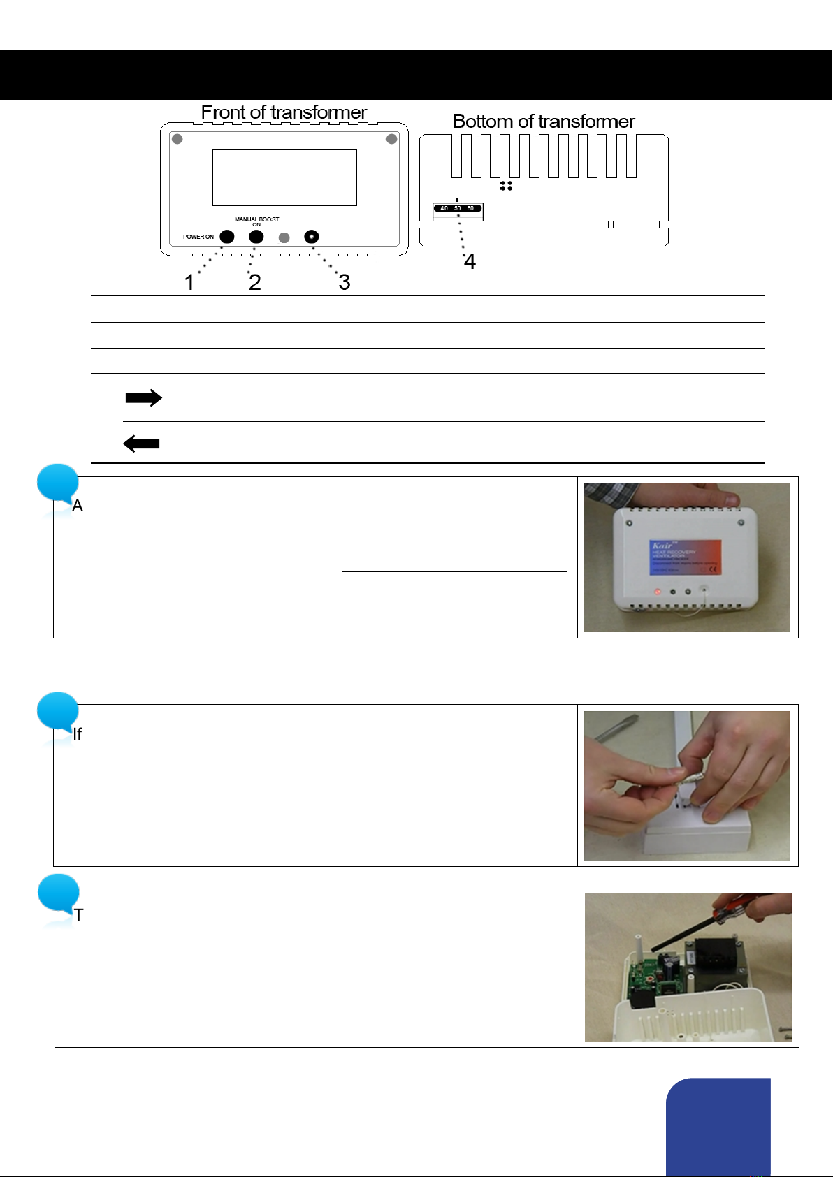
A humidity sensor measures the moisture content of the air. If the level rises beyond the set
threshold, the humidity sensor switches to boost. The threshold is adjusted using the dial on the
bottom edge of the transformer. The unit should be set at 50% as standard for ideal humidity
levels.
What are the filters for?
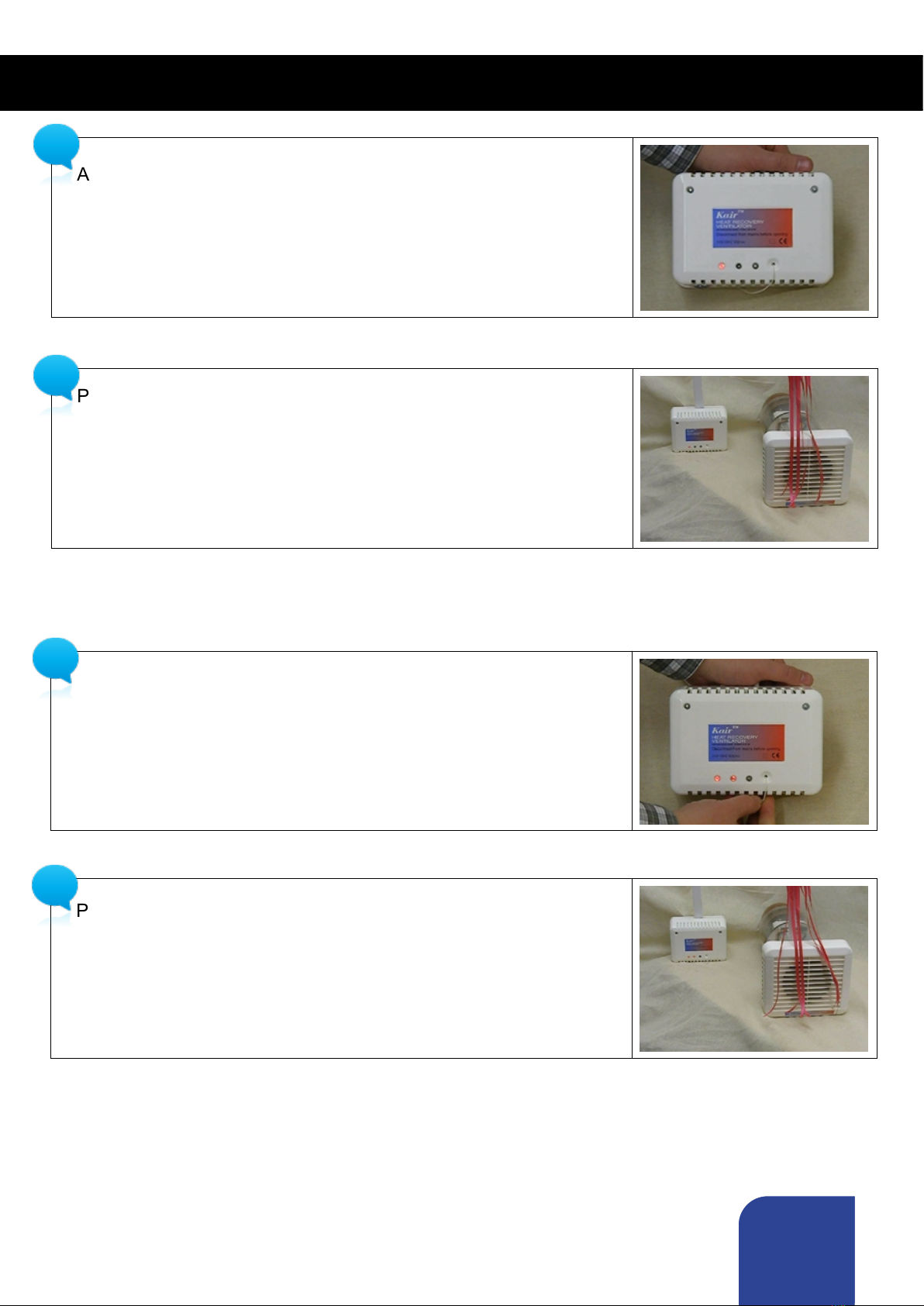
Filters clean the air coming into the building to keep it free of dirt, smoke particles etc. Our units
also filter the extracted air to protect and prolong the life of the heat exchanger, keeping it clean
to keep it functioning efficiently. Pollen filters are also available, with a denser, finer mesh, to
prevent allergens entering through the fan.
The unit is blowing in cold air!
This could mean the filters are clogged or blocked, which means less warmth is passed through
the heat exchanger. What colour are the filters? If grey or black, they need cleaning or replacing.
- Check the outside cowl is still attached to prevent cross-contamination.
- Is your heating on? If the room is cool, the fan cannot recover much, if any, heat. The unit only
recovers heat, it does not generate it.
- The heat exchange efficiency is less when the unit is on boost.
Moving air can feel cooler. Blow on your hand slowly, then quickly. The quicker air will feel cooler.
The unit won't come off boost!
Are two lights on? If yes, can you pull the pullcord? If nothing happens, the pullcord may be
snagged. Isolate the mains, remove the transformer housing and make sure the pullcord is not
tangled or snagged.
The unit won't come on to boost!
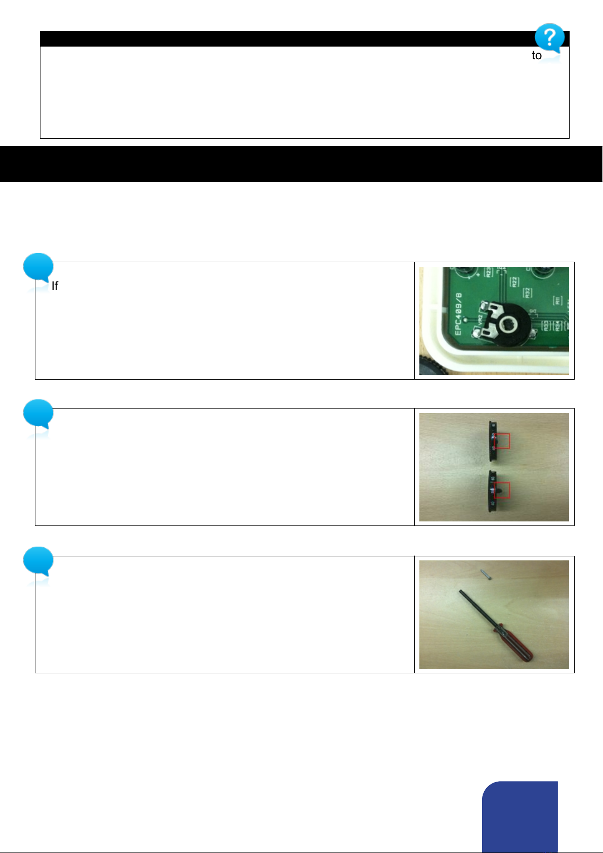
The humidity sensor may be damaged, or the white rheostat may have been adjusted by
mistake. This needs to be re-calibrated using another humidity meter.
Can I switch off the unit?
This unit is designed to run constantly providing background ventilation and should be left on at
all times.
Other Frequently Asked Questions
The unit comes onto boost at night time.
The night sensor is improperly set. See page 4

Page
11
Can I slow down the unit?
Put the fuse in the slow position. See page 7
What thickness of wall/length of ducting l can I install the unit into?
Up to 2 metres for mildly affected rooms, using the 1m extension kits we supply.
How do you drill through a metre thick wall?
With a long drill bit. Available from specialist suppliers. You could also drill from both sides and
meet in the middle, or use extension drill bits.
There is water in the unit or I get water on walls around the unit
The core drilled hole should always be drilled at a 3 degree downward angle towards the outside.
Interiors of holes drilled below ground level should be sealed, for example with mastic.
At what height in my room should I mount the unit?
Warm air rises, so the higher you mount the unit, the more heat you will recover.
Where should I mount the transformer?
Ideally 150mm below ceiling level, to allow a good amount of light to get to the sensor.
Can you mount the unit through a roof?
No, because rainwater, or condensation will drip out of the fan.
I've installed the machine but I still have mould.
What setting is the dial at? Usually it should be set at 45-55. Did you clean the mould off? How
long ago? What with? Bleach won't work, as it is a germicide not a fungicide (mould is a fungus).
These machines won't actually clean mould off your walls. They will only stop it re-growing. Are
there obstacles to air circulation like bulky furniture, or over-packed wardrobes? Do you
habitually dry your laundry in that room? Do you close your bathroom and kitchen doors?
Leaving them open will increase demand on a unit in a different room.
I have mould in odd straight or regular patterns, despite having an HRV unit installed.
Cold bridging - the disruption of cavity walls or insulation by a solid material allows the outside
temperature to penetrate. This results in stripes of mould over beams or spots over nail heads.
Our units are not designed to deal with this, rather it is a physical characteristic of your building
and needs a separate treatment such as thermal wallpaper or anti condensation coating.
Can I use a different humidistat?
Yes you can, but you would need a separate transformer from 240v to 12vAC, as well as a
separate humidistat.

Page
12
Version: 20130731
The warranty
Applicable only to products installed and used in the United Kingdom. For details of warranty outside
of United Kingdom, contact your local supplier.
Kair guarantees its products for two years from date of purchase against faulty material or
workmanship. In the event of any part being found to be defective, the product will be
repaired, or at the Company’s option replaced, without charge, provided that the product:
●Has been maintained / serviced in accordance with instructions given.
●Has been installed and used in accordance with the instructions given with each unit.
●Has not been connected to an unsuitable electrical supply.
●Has not been subject to misuse, neglect or damage.
●Has not been modified or repaired by any person not authorised by the company.
IF CLAIMING UNDER TERMS OF GUARANTEE
Please return the complete product, carriage paid to your original supplier or nearest Kair centre, by
post. Please ensure that it is adequately packed and accompanied by a letter
clearly marked “Guarantee Claim” stating the nature of the fault and providing evidence of date and
source of purchase.
The guarantee is offered to you as an extra benefit, and does not affect your statutory rights.
Phone: 08451 66 22 40
Fax: 08451 66 22 50
Web: www.kair.co.uk
Email: [email protected]
Address: 6 Chiltonian Industrial Estate, Manor Lane,
Lee, London SE12 0TX
As part of our policy of continuous product development, Kair reserves the right to alter specifications without notice.
Register your unit online now. If you register within 14 days of purchase you will receive an
extra filter set free.
Step 1
You will need the following information to hand to register your first set of replacement filters FREE.
●The serial number of your HRV unit. (Found on the packaging box or inside left filter cover)
Date of purchase.
Your full name and address - including post code
Your email address
Step 2
Fill in the online form, visit www.kair.co.uk/register or scan this QR code.
Step 3
Once we have received your fully completed registration we will despatch your FREE filters.
Registration
Other manuals for KHRV150/12RH
1
Table of contents
Other Kair Fan manuals
Popular Fan manuals by other brands

Greenheck
Greenheck GreenJet GJI Installation, operation and maintenance manual

Broan
Broan 349BR instructions

Klimawent
Klimawent WPA-D-N Series Use and maintenance manual

TEFAL
TEFAL EOLE INFINITE VU66 Series user guide

RenewAire
RenewAire BR Series Installation, operation and maintenance manual

ARDES
ARDES AR5EA41PB Instructions for use