Kaise ET7830 User manual

CATⅢ
300V
CATⅠ
600V
LOW CU R R E N T DC CL AM P M E T ER
4000mA
40A / 200A
S K-7 8 3 0
OFF
0ADJ
DIFF
1sec<
( )
DH
MAX 200A
CATⅢ
300V
CATⅠ
600V
LOW CUR R EN T D C CL AM P M E TE R
4000mA
40A/ 200A
SK -78 3 0
OFF
0
ADJ
DIFF
1sec<
( )
DH
MAX200A
CATⅢ
300V
CATⅠ
600V
LOW CU R RENT DC CLA M P M ETER
4000mA
40A/ 200A
SK-7 8 3 0
OFF
0
ADJ
DIFF
1sec<
( )
DH
MAX200A
3. SAFETY PRECAUTIONS
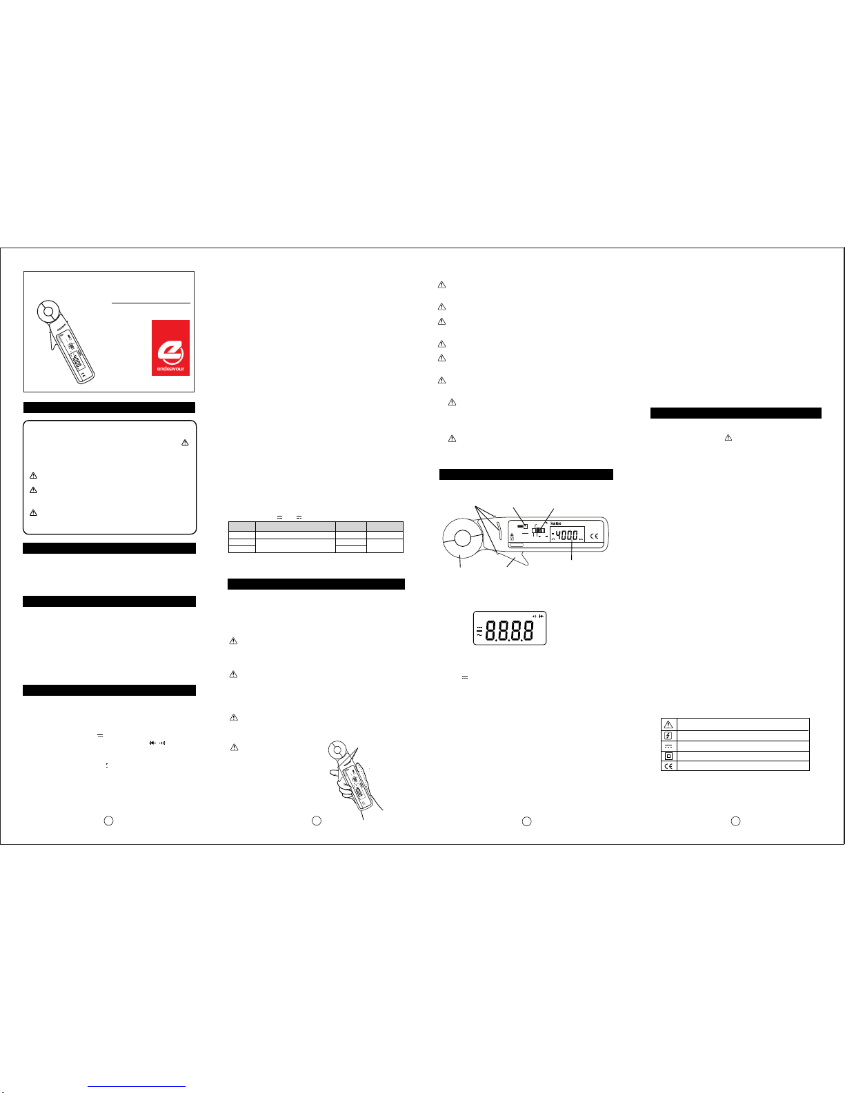
4. NAME ILLUSTRATION
(23℃±5℃、<80%RH in non-condensing)
1. DC CURRENT ( mA, A)
WARNING 1. Checks of Clamp Meter Body
WARNING 2. Warning for High Power Line Measurements
WARNING 3. Maximum Input Observance
234
2-2. MEASUREMENT SPECIFICATIONS
3-1. WARNINGS
3-2. GENERAL WARNINGS AND CAUTIONS
Children and the persons who do not have enough
knowledge about electric measurements must not
use this instrument.
Do not measure the electricity naked or barefooted to
protect yourself from electrical shock hazard.
Do not polish the case or attempt to clean it with any
cleansing fluid like gasoline or benzine. If necessary,
use silicon oil or antistatic fluid.
Avoid the clamp meter from hard mechanical shock or
vibration, high temperature and strong magnetic field.
Remove the batteries when the clamp meter is out of
use for a long time. The exhausted batteries might
leak electrolyte and corrode the inside.
Do not measure AC high-frequency current. Clamp
head becomes heated and could damage the
instrument.
Do not make a measurement under large
temperature difference. In case that the clamp meter
moved into high temperature place from low
temperature, turn the power on and leave it for a
while to get it used to the surrounding temperature.
When measuring, open clamp head 15mm or
wider and close it softly. Detach fingers from trigger
after clamping a conductor.
WARNING 1.
WARNING 2.
CAUTION 1.
CAUTION 2.
CAUTION 3.
CAUTION 4.
FOR SAFETY MEASUREMENTS!!
INTRODUCTION
1. UNPACKING AND INSPECTIONS
1
To prevent an electrical shock hazard to the operator and/or
damage to the instrument, read this instruction manual carefully
before using the Clamp Meter. WARNINGS with the symbol
on the Clamp Meter and this instruction manual are highly
important.
Important Symbols
The symbol listed in IEC 61010-1 and ISO 3864 means
"Caution (refer to instruction manual)".
WARNING : The symbol in this manual advises the user
of an electrical shock hazard that could result in serious
injury or even death.
CAUTION : The symbol in this manual advises the user of
an electrical shock hazard that could cause injury or
material damages.
Thank you for purchasing ET7830 LOW CURRENT DC
CLAMP METER". To obtain the maximum performance of
this instrument, read this Instruction Manual carefully, and take
safe measurements.
Inspect the instrument and accessories for transport damage.
If there is any damage or missing items, ask your local dealer
for replacement.
Confirm that the following items are contained in the package.
1. Digital Clamp Meter
2. Carrying Case (1011)
3. Batteries (1.5V R6P)
4. Instruction Manual
8. DISPLAY HOLD : Hold indicating values by DH Key
9. ZERO-ADJUSTMENT (DIFFERENCE MEASUREMENT) :
Adjust LCD into 0±1 digit and/or start Difference Measurement by
0 ADJ (DIFF) Key.
10. AUTO POWER OFF : Power turns off automatically after a lapse
of following minutes.
a. 4000mA range : Approx. 5 minutes
b. 40A/200A range : Approx. 10 minutes
11. OVERLOAD PROTECTION : 400A AC/DC rms for 1 minute
(50/60Hz)
12. DIELECTRIC STRENGTH : 3.54kV AC, 50Hz sine wave, for 1
minute (between iron core and case)
13. OPERATABLE TEMPERATURE & HUMIDITY :
0℃to 40℃, 80%RH or lower in non-condensing.
14. STORAGE TEMPERATURE & HUMIDITY :
-20℃to 60℃, 70%RH or lower in non-condensing.
15. TEMPERATURE COEFFICIENT : Accuracy in 23℃±5℃×0.1/℃
16. SAFETY LEVEL : CE Marking approved (IEC-61010-1, CAT Ⅲ
300V, CATⅠ600V and EMC Test passed.)
17. POWER SUPPLY : 1.5V R6P (AA) batteries ×2
18. POWER CONSUMPTION : 26mA max.
19. CONTINUOUS OPERATING TIME : Approx. 60 hours (Alkaline
cell), Approx. 30 hours (Manganese cell) (in 40A/200A range, 0A
input)
20. CONDUCTOR DIAMETER : φ20mm max.
21. DIMENSIONS & WEIGHT : 203(H)×61(W)×30(D)mm,
Approx. 230g (including batteries)
22. ACCESSORIES : 1011 Carrying Case, 1.5V R6P (AA) batteries
×2, Instruction Manual
2. SPECIFICATIONS
, −, 〜, mA, A, mV, V, Ω, kΩ, MΩ,
Hz, kHz, %, nF, μF, , , DH, DIFF,
PH, MAX, MIN, APO, BAT, AUTO, LPF
and decimal point.
Σ
2-1. GENERAL SPECIFICATIONS
1. DISPLAY (LCD)
a. Numerical Display : 4000 count, Maximum reading 4050,
12mm high
b. Units and Symbols :
2. OPERATING PRINCIPLE : ⊿conversion
3. SAMPLING RATE : 64 times / second(Display : 1time/second)
4. RANGE SELECTION : Manual-ranging(4000mA),
Auto-ranging(40A/200A)
5. POLARITY : Auto-Polarity ("ー" indication in minus)
6. OVERLOAD INDICATION : "OL" indication blinks
7. BATTERY WARNING : "BAT" indication at approx. 2.3V or less
Do not measure any current that might exceed the specified
maximum input values.
WARNING 4. Safety Line
Do not put your fingers over the
safety line while current
measurement. (Refer to fig.1)
Correct knowledge of electric measurements is essential to avoid
unexpected danger such as operator's injury or damage to the
instrument. Read carefully and observe the following precautions for
safe measurement.
Before measurement, confirm the body of this instrument has no
cracks or any other damages. Dust, grease and moisture must be
removed.
High Power Line (High Energy Circuits) such as Distribution
Transformers, Bus Bars and Large Motors are very dangerous. For
safety of high power line measurement, do not touch the live line and
keep enough distance.
LOW CURRENT
DC CLAMP METER
ET7830
INSTRUCTION MANUAL
Range
4000mA
40.00A
200.0A
Resolution
1mA
10mA
100mA
Max.Input
Current
Overload Protection : 400A AC/DC rms (for 1 minute) (50/60Hz)
Range Selection : Manual-ranging / Auto-ranging
Accuracy
±1.5%rdg±5dgt (from 5mA)
200A DC
4000mA DC
LCD
DH Key
Trigger
0 ADJ (DIFF) Key
Clamp Head
FUNCTION Switch
Safety Line
Turns the power on and selects measurement functions. After
measurement, turn it to "OFF".
4-4. FUNCTION Switch
Opens and closes the clamp head. When measurement, open
clamp head 15mm or wider and close it softly. Detach fingers from
trigger after clamping a conductor.
4-7. Trigger
Holds indicating measurement values. ("DH" lights up)
To cancel it : Press DH key again.
4-5. DH Key : Display Hold
Zero-Adjustment : Press this key for 1 second or more when
zero-point adjustment is necessary. LCD indications are adjusted
into 0±1 digit.
Difference Measurement : Press this key for 1 second or more
while measurement. Convert a measurement value into zero and
indicate the relative values.
To cancel it : Press 0 ADJ (DIFF) Key for 1 second or more.
4-6. 0 ADJ (DIFF) Key :
Clamp on a single conductor to measure DC current.
NOTE : Unable to measure if several conductors are clamped.
AUTO
BAT
−
APO
DH
DIFF
mA, A
Lights up in auto-ranging measurement
Low battery warning
Lights up at minus
Lights up in DC current measurement
Auto power off indication
Lights up in display hold function
Lights up in zero-adjustment and difference
measurement
Lights up in current measurement
:
:
:
:
:
:
:
:
4-1. LCD
4-2. Clamp Head
The line to protect yourself against electrical shock hazard. Do
not put your fingers over this line while measuring current.
4-3. Safety Line
AUTO DH DIFF MAX MIN
PH
BAT LPF
APO
kMΩ
%mVA
Hz F
μ
n
1pce.
1pce.
2pcs.
1pce.
(0 to 100A)±1.5%rdg±5dgt
(101 to 200A)±3.0%rdg±5dgt
(
fig.2
fig.1
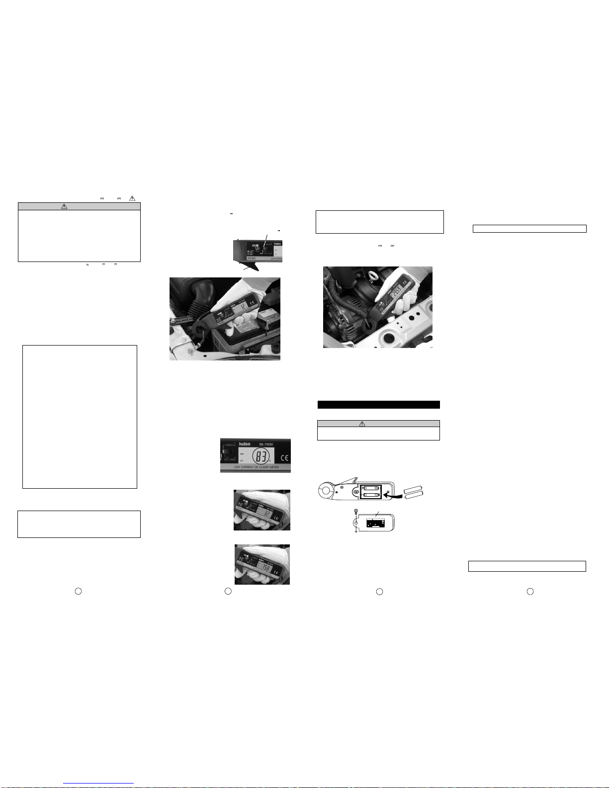
Before using this instrument, install 2 of 1.5V R6P (AA) batteries
refering to 「6-1. BATTERY REPLACEMENT」. Replace them in
the same way when "BAT" lights up on LCD.
5-1. PREPARATION FOR USE
1. INSTRUCTION MANUAL
Read INSTRUCTION MANUAL carefully to understand the
specification and functions correctly. 「3. SAFETY
PRECAUTIONS」is highly important for safe measurement.
2. BATTERY
"OL" lights up on LCD if measurement value exceeds maximum
indicatable value of each measurement range (4050 digits or 2050
digits).
3. OVERLOAD INDICATION
5. MEASUREMENT PROCEDURES
Power turns off automatically after approx. 5 minutes (4000mA
range) or after approx. 10 minutes (40A/200A range) of last
FUNCTION Switch operation to conserve battery life. (Small-
current-consumption remains. After measurement, be sure to set
FUNCTION Switch to "OFF".)
To cancel it (40A/200A range only) : Hold down DH Key and set
FUNCTION Switch from "OFF" to "40A/200A". Auto power off is
canceled and "APO" disappears from LCD.
NOTE : Auto power off cannot be canceled in 4000mA range.
4. AUTO POWER OFF
Safety Line
1 :
2 :
Caution (refer to instruction manual.)
Caution for current-applied dangerous conductor
Direct Current (DC)
Double Insulation
CE Marking Conformity
The following symbol marks shown on the instrument and
instruction manual are listed in IEC 61010-1 and ISO 3864.
Automatic zero-adjustment function to adjust LCD indications into
0±1 digit when powered on.
NOTE :
NOTE :
5. POWER-ON INITIALIZE
6. SYMBOL MARK
INITIALIZE does not work properly if some inputs are
applied.
Do not touch trigger when turning on the power.
INITIALIZE does not work correctly if any pressure is
applied to trigger or clamp head is opened.
*Accuracy after zero adjustment

70-1201-7830-2 0807
Do not measure any current that might exceed maximum
input value (200A DC / 600V line).
Read 「3. SAFETY PRECAUTIONS」carefully to avoid
electric shock hazard and serious damage to the instrument.
Do not twist clamp head while measurement. Measurement
should be incorrect if any pressure is applied to the clamp
head.
Do not touch any part of power line or the circuit to be
measured.
Set FUNCTION Switch to " or ".
NOTE :
Do not touch trigger nor open clamp head until
POWER-ON INITIALIZE is completed and LCD
indicates 0±1 digit.
Supporting Functions :
Zero-Adjustment, Difference Measurement, Display Hold (Refer
to 4-5 and 4-6).
When taking measurement in 4000mA range, to reduce
geomagnetic effect to the measurement, zero
adjustment by POWER-ON INITIALIZE must be taken
just in front of a conductor to be clamped, fixing the
clamp head angle on measuring position.
NOTE : LCD indication may not return to 0mA by
geomagnetic effect if changing clamp head angle after
measurement taking clamp head away from a
measured conductor.
When measuring low current at 1000mA or lower, take
zero adjustment by POWER-ON INITIALIZE for every
measurement.
LCD indication may not return to "0" by magnetic effect,
if high current is instantaneously applied during high
current measurement at 100A or higher, or regular
measurement in each range.
Under 4000mA range measurement, ±15mA current
fluctuation from measuring value is not displayed on
LCD by internal control.
Zero-point fluctuation occurs depending on
temperature alteration of measurement environment
that could cause LCD indication not to return to "0" or
large measurement deviation.
NOTES : Following instructions are important to take
an accurate measurement.
4000mA range needs a few seconds until LCD
indications become stable.
Open clamp head 15mm or wider and close it softly. Detach
fingers from trigger after clamping a conductor.
Read the measurement value on LCD.
NOTE :
After measurement, unclamp from the conductor and set
FUNCTION Switch to "OFF".
1.
2.
3.
4.
Endeavour Tools guarantees this unit against defects in material
and workmanship for a period of twelve (12) months from the date
of purchase.
A.Endeavour Tools warrants the quality of these goods against
defects in material and workmanship only.
B. Defective goods shall only be replaced, repaired or purchase
price refunded if:
a.The customer notifies Endeavour Tools by providing a full report
describing the defect in writing within 7 days of the discovery of the
defect; and
b.The notification above provided to Endeavour Tools is prior to
the expiry of the warranty period;
c.The customer forwards the defective goods together with proof of
purchase from Endeavour Tools; or its authorized distributor at
their expense, within 14 days of any request by Endeavour Tools
to do so;
d.The goods since the date of delivery to the customer have been
properly maintained, stored and housed and the goods have not
been abused or modified or the case opened;
C. Endeavour Tools may replace or repair the defective good (or
part thereof) or refund the purchase price of the defective good at
its option.
D. Endeavour Tools shall not be responsible for any loss or
damage arising from or in any way connected with the use of the
goods.
E.To the maximum extent permitted by law, a claim in respect to a
defective good shall not be permitted in the event that the goods
have not been installed, used, maintained, or housed in a proper
and workmanlike manner or in accordance with the usual
standards or manufacturers specifications or instructions or if the
goods have been modified, repaired or altered by any person apart
from Endeavour Tools.
Notwithstanding our warranty terms above, our goods come
with guarantees that cannot be excluded under the Australian
Consumer Law. You are entitled to a replacement or refund
for a major failure and for compensation for any other
reasonably foreseeable loss or damage. You are also entitled
to have the goods repaired or replaced if the goods fail to be
of acceptable quality and the failure does not amount to a
major failure.
The benefits under our warranty are in addition to other rights and
remedies under law in relation to the goods.
Check the battery connection, polarity, and capacity ("BAT"
lights up or not).
Confirm that FUNCTION Switch is set to the correct position.
Confirm that measured accuracy is adopted in the operating
environment.
Confirm that the body of this instrument has no cracks or any
other damage.
Periodical check and calibration is necessary to make safety
measurements and to maintain the specified accuracy. The
recommended check and calibration term is once a year and after
arepair service. This service is available through your local dealer.
Repair service is available through your local dealer. Pack the
instrument securely with your name, address, telephone number
and problem details, and ship to your local dealer.
5-2. DC CURRENT MEASUREMENT ( mA / A)
Dark Current :
mA-level low current that is used after turning off the engine by such as
car security system or audio settings back-up. Too much dark
current causes battery depletion, but its measurement is difficult. ET7830
solvesthis problem and makesit quick and easy.
Clamp-on a minus cable of car battery.
Read the measurement value on LCD.
NOTE : The values should be minus (−) if the current flows
opposite direction of "⇒" mark on clamp head.
If measurement value is higher than the specified value, check if
any of car lamps remain lighting.
NOTE :
POWER-ON INITIALIZE
does not work properly.
The specified dark current value becomes different if the
optional electric components such as car navigation or
security equipments are attached. In that case, refer to
their user manuals for details.
Measurement value should be
incorrect.
NOTE :
Especially for the cars that ECU
or other electric components
keep working for a certain
period of time after turning off
the engine, or have LCD fuel
meter.
Cannot measure dark current.
Turn the all lamps off.
Leave the car engine turned off for about 15 minutes after
setting battery cable into the measurable condition. All electric
components such as door lamp, room lamp, and headlight
must be turned off. Lock the all doors if measuring car has
remote-control door lock function.
NOTE : Leaving time is different depending on the car
functions, especially for the cars that ECU or other electric
components keep working for a certain period of time after
turning off the engine, or have LCD fuel meter.
NOTE : Cool down the engine before measurement, in case that
measuring cable is close to the engine.
Put the clamp head close to a battery cable to be measured. Set
FUNCTION Switch to "4000mA" without touching the trigger.
POWER-ON INITIALIZE works to adjust LCD display into "0"
automatically. (Refer to fig. 3)
WARNINGS
●
●
●
●
6-1. BATTERY REPLACEMENT
6-2. PERIODICAL CHECK AND CALIBRATION
6-3. REPAIR
WARNING
WARRANTY
1.
2.
3.
4.
1.
2.
3.
4.
Replace the batteries when "BAT" lights up on LCD.
Check the following items before asking for repair service.
To avoid electrical shock, detach instrument from circuit
when replacing battery. Set FUNCTION Switch to "OFF".
Turn the power off.
Unscrew the Baterry Cover and remove exhausted batteries.
Insert 2 of new 1.5V R6P (AA) batteries in correct polarity.
Fix battery Cover and tighten the screw.
fig.9
6.MAINTENANCE
678
5
4000mA 40A / 200A
●MEASUREMENT EXAMPLE 1.
Automobile Dark Current Measurement
●MEASUREMENT EXAMPLE 2.
●Example of Incorrect Measurement
Measurement of Car Alternator's Charging Current
Turn the power on with clamp head opened.
Start measurement with any of car lamps remain lighting.
Start measurement as soon as engine stopped.
R6P(AA)
+
−
+ −
Screw Battery Cover
Two 1.5V R6P Batteries.
1.5V
1.5V
KAISE JAPAN
4201-7830-1 0708
WARNING
MAX. 200A
BATTERIES: 1.5V R6P×2 26mA MAX.
OVERVOLTAGE CAT. 300V CAT. 600V
SERIALNO.
ⅢⅠ
TO A VOID ELEC TRIC AL S HOCK ,
DETACH INSTRUMENT FROM CIRCUIT
WHENTO REPLACE BATTERY.
Trigger
①
②
③
④
⑤
Start the engine, and read the measurement value on LCD.
NOTE : The value should be minus (−) if the current flows
opposite direction of "⇒" mark on clamp head.
Alternator has no problem if 20A to 40A is displayed first, and
then it slowly becomes lower.
Alternator should be defective if no value is indicated, or high
current value remains indicated.
③
④
⑤
⑥
①
②
③
①
②
Stop the car engine.
Set FUNCTION Switch to " " .
Be sure not to touch trigger. (Refer to fig. 8)
Clamp-on B-terminal cable from car alternator.
fig.3
fig.4
fig.8
fig.5
fig.6
fig.7
4000mA
Product specifications and appearance are subject to change without
notice due to continual improvements.
Car Alternator:
Automobile engine generator that outputs DC electricity. Measuring its
charging current is effective to find the trouble that might cause battery
depletion or battery damage.
40A / 200A
1.
2.
3.
4.
5.
Other Kaise Measuring Instrument manuals
Popular Measuring Instrument manuals by other brands

Snap-On Diagnostics
Snap-On Diagnostics DGA 1000 manual

SIGMA SPORT
SIGMA SPORT INLINE SPEED CHIP manual

Ultraflux
Ultraflux Minisonic Series user manual

Ecom
Ecom ECOM-D operating instructions

ElektroPhysik
ElektroPhysik MiniTest 7200 FH Technical manual and operating instructions

Atomos
Atomos Ninja Blade quick start guide

Haldex
Haldex Modular Trailer System Installation & service manual

Tektronix
Tektronix WVR7200 Technical reference

Mitsubishi Electric
Mitsubishi Electric Super-S ME96SSEA-MB user manual

Endress+Hauser
Endress+Hauser LPGmass manual

Sun-Tech
Sun-Tech Vet30 M30A user manual

HIKOKI
HIKOKI UB18DB Handling instructions