itaia FM-6 User manual

Operating manual
Photometer: FM-6
Litostrojska cesta 44/d, SI-1000 Ljubljana
T +386 (1) 514 18 00, F +386 (1) 514 18 04
ELECTRONICS
RESEARCH
DEVELOPMENT


Table of Contents
1. SAFETY INFORMATION AND CAUTION...........................................1
1. 1. GENERAL................................................................................................1
1. 2. FIRE-EXTINGUISHING GEAR .............................................................2
1. 3. SAFETY PRECAUTIONS.......................................................................2
2. GUIDELINE FOR CONNECTION AND USE OF PHOTOMETER...4
2. 1. FIELD OF USE ........................................................................................4
2. 2. MOUNTING AND PLACEMENT..........................................................4
2. 3. CONNECTIONS......................................................................................4
2. 4. ONBOARD INDICATORS......................................................................6
2. 4. 1. Serial Communication Port..........................................................................6
2. 4. 2. Use of 230 V AC Contactor Outputs.............................................................7
2. 4. 3. Use of U/I/f Analog Outputs .........................................................................7
2. 5. CALIBRATION .......................................................................................8
3. PC SOFTWARE »STREET LIGHT VISION«.........................................9
3. 1. WRITING DATA TO THE PHOTOMETER ........................................ 10
3. 2. READING DATA FROM THE PHOTOMETER..................................11
3. 3. SETTING UP PC COMMUNICATION................................................12
3. 4. DATA LOGGING..................................................................................14
4. MAINTENANCE......................................................................................15
4. 1. CHECKING AND MAINTENANCE....................................................15
4. 2. SERVICING...........................................................................................15
4. 3. TROUBLESHOOTING..........................................................................16
4. 4. SPARE PARTS.......................................................................................16
5. TECHNICAL DATA................................................................................17
5. 2. TRANSPORT AND STOCKING ..........................................................18
5. 3. DISPOSAL .............................................................................................18
6. CE DECLARATION OF CONFORMITY ............................................18
7. WARRANTY OBLIGATIONS...............................................................18

Operating manual: PHOTOMETER FM
-
6
1
1. Safety information and caution
1. 1. General
The device, connected and used in accordance with following instructions, is safe to use.
All electrical parts are protected against water, dust and dirt by the relevant IP class.
Housing prevents direct contact with any parts under voltage.
! CAUTION: For any injury resulting from
improper use, the user
takes full responsibility.
!
BEFORE MOUNTING AND CONNECTING THE
DEVICE READ MANUAL CAREFULLY!
!
THE CONNECTING OF DEVICE MUST BE CARIED
OUT BY QUALIFIED PERSONNEL!
!
WHEN CONNECTING, DISCONNECT ELECTRICAL
POWER FIRST!
!
DO NOT BLOCK ACCESS TO ELECTRICAL PARTS
USED FOR EMERGENCY STOP, CLEANING AND
MAINTENANCE!
!
ALL METAL PARTS OF HOUSING MUST BE
GROUNDED!
!
MAKE SURE THAT WATER DOES NOT GET IN
TOUCH WITH PARTS UNDER VOLTAGE!
Connecting of the device must be done by qualified personnel and in accordance with
local standards. After mounting and connection control measurements must be carried
out to ensure safe and correct operation.
!

Operating manual: PHOTOMETER FM
-
6
2
1. 2. Fire-extinguishing gear
In case of fire use CO
2
based fire extinguisher and other equipment following procedures
in accordance with fire-safety regulations.
1. 3. Safety precautions
Safety precautions are meant to provide personal safety and long service life of device.
Any person take part of mounting, connecting or maintenance of the device must follow
this manual and local safety regulations. They have to be qualified for the job and use
appropriate technical equipment.
Before starting:
Disconnect circuit breakers at input and output of the device and make
sure there is no voltage present.
Make sure power is disconnected during the time of mounting and
connecting.
Check the voltage presence with an instrument.
Check grounding connection.
Provide protection against touching the parts under voltage.
Qualified personnel
Transport, mounting, connecting, commissioning and maintenance of the device can
only be performed by personnel:
with job qualification and experience,
familiar with up to date safety standards and
with knowledge of basic working principles of the device.
Responsibility
We take no responsibility for proper operation and any consequences resulting from use
in discordance with this manual. Safety measures must be provided by user working with
device.
In case of malfunction, please, provide us following information:
type of the device,
serial number,
errors detected,
overall time of operation,
environmental conditions and
application information.

Operating manual: PHOTOMETER FM
-
6
3
Our Technical Support
Litostrojska cesta 44/d, SI-1000 Ljubljana
T +386 (1) 514 18 00, F +386 (1) 514 18 04
[email protected], www.itaia.si
Declaration Of Conformity
The device complies with relevant European directives (CE declaration of conformity):
– Electromagnetic compatibility (ULRS, no. 132/2006)
Directive 2004/108/EC and its amendments
– Low voltage Directive (ULRS, no. 27/04)
Directive 2006/95/EC and its amendments

Operating manual: PHOTOMETER FM
-
6
4
2. Guideline for Connection and Use of Photometer
2. 1. Field of Use
Photometer is designed for measuring and regulation of traffic area illumination. Based
on L
20
measurement according to CIE standard it establishes adequate illumination at
any time of day and any light conditions. Integrated logic controller and software provide
complete solution for tunnel lighting regulation with no external controller necessary.
Photometer FM-6 is provided with analogue U/I/foutputs for additional PLC or SCADA
connection. For local lighting control 6-channel 230 V AC, programmable, contactor-
driving outputs are available. Full function control, measuring range, output channel
switching and time averaging interval are PC programmable using software provided.
2. 2. Mounting and Placement
Photometer comes with wall/pole fixture; special pole fixture is also available (optional).
When used for tunnel entrance portal-lighting measurement, the photometer is installed
at the stopping distance before the tunnel entrance. It should be pointed directly to the
entrance. Mounting on pole, take special care for proper pole grounding, including any
foldings or joints!
When it is used to measure in-tunnel light conditions, it should be mounted at the height
of app. 4.5 metres and pointed to the spot one reach in 3 seconds at maximum allowed
speed. In this case the driver’s view cannot be simulated accuratley due to mounting
height and measuring result shlold be adopted by correction factor (usually between 1.05
and 1.20). For in-tunnel use, especially in long tunnels choose full-stainless steel
hausing option.
Once mounted, undisturbed view-field of the photometer must be provided. There should
be no light sources, either any light reflecting objects in the view-field of the photometer.
Any of those can considerably affect light measuring accuracy.
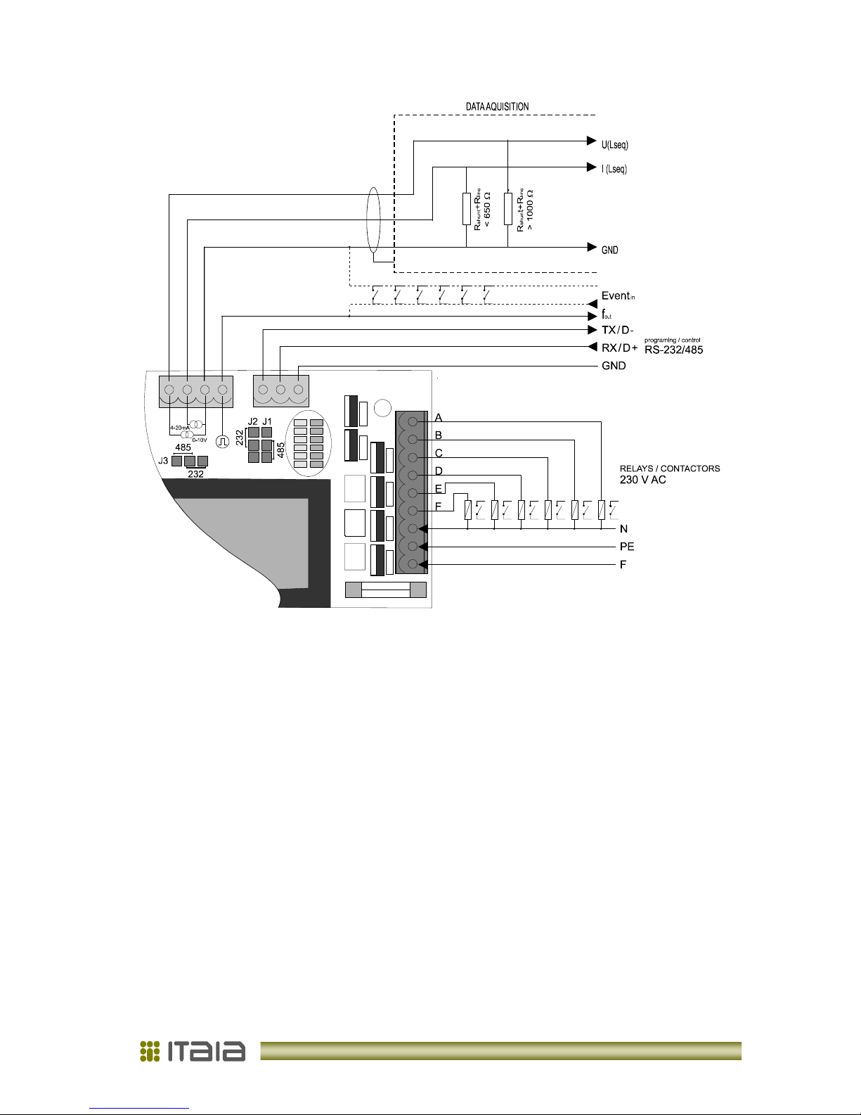
2. 3. Connections
Photometer is connected to the mains power supply 230 V AC and to the tunnel light
controlling system. All connections are done from the back side with cover removed. Cables
of 3-9 leads and minimum 0.75 mm
2
must be used for 230 V AC power outputs. For
analogue U/I/foutputs and communication coaxial 2-4 lead data cables are recommended.
Maximum connection distance is up to 400 metres.
After final connection and successful commition place desiccant bag provided in the
photometer’s housing and push it towards front window. Take care it is not touching any
electrical part! Cable inlet-glands and back cover must be well tightened after final
connection!

Operating manual: PHOTOMETER FM
-
6
5
Picture 1: Connectors behind the rear cover
Table 1: Pin out and description
pin port voltage description
1 L-
power
230 V AC power
2
PWR
ground / grounding
3 N-
power
230 V AC power
4 out F 230 V AC
contactor out. F
5 out E 230 V AC
contactor out. E
6
contactor
out D 230 V AC
contactor out. D
7
out
out C 230 V AC
contactor out. C
8 out B 230 V AC
contactor out. B
9 out A 230 V AC
contactor out. A
10
PC
GND 0 V DC
programming/control
11
RS 232
RX/ D+
±
12 V DC
programming/control
12
/485
TX/ D-
±
12 V DC
programming/control
13
LOGICI/O
f
port
0-15 V DC
freq./range
out
; Event
in
14
analog
GND 0 V DC
15
analog
I
out
4-20 mA current output
16
analog
U
out
0-10 V DC voltage output

Operating manual: PHOTOMETER FM
-
6
6
Picture 2: Photometer connection
2. 4. Onboard Indicators
From back side visible LED indicators on PCB indicate current light conditions - green and
contactor output status – red (see Picture 1). Other LEDs are status indicators and have no
meaning forthe user.
2. 4. 1. Serial Communication Port
The photometer's selectable communication port can be configured for RS-232 or RS-485.
Set jumpers J1...J3 to select the protocol. Connection distance can be up to 20 m for RS-
232 and 300 m for RS-485. Communication supports the complete set of photometer’s
functions, setup parameters and output values.
When serial communication is used for on-line data transfer always choose RS-485. Use
RS-232 for parametric setup or laboratory use only.

Operating manual: PHOTOMETER FM
-
6
7
2. 4. 2. Use of 230 V AC Contactor Outputs
Outputs can be directly connected to the coil-side of contactors for light-chain switching
(check contactor’s coil voltage!). Use PC software to distribute switching combinations.
Example is shown at Table 2.
regulation light
output
A
B
C
D
E
F
LED
level condition
pin
9 8 7 6 5 4
green,red
1
2
3
4
5
6
0
B<L1
230 V AC / / / / / ON / / / / /
1
B>L1;B<L2
/ 230 V AC / / / / / ON / / / /
2
B>L2;B<L3
/ 230 V AC 230 V AC / / / / ON ON / / /
3
B>L3;B<L4
/ / / 230 V AC / / / / / ON / /
4
B>L4
230 V AC 230 V AC / 230 V AC / / ON ON / ON / /
Table 2: Indicating LEDs and contactor outputs
Green LEDs indicate estimated switch-level combination (no averaging delay) due to current
light condition. Red LEDs indicate current status of 230 V AC outputs (averaging affected).
For example : At first level LED-A is lit when light conditions are within the limit set for L1.
After preset averaging time, the red LED-A and contactor output A will be switched on.
2. 4. 3. Use of U/I/fAnalog Outputs
Analog outputs directly follow current light conditions (no averaging is applied). There are
voltage (0-10 V), current (4- 20 mA) and frequency (1 Hz-10 kHz) outputs for this purpose.
Simultaneous use of more than one is not recommended and can affect accuracy. However
230 V AC contactor outputs can be used at the time with no affect to accuracy. For example:
tunnel lighting can be switched using contactor outputs while light conditions are monitored
via analog output.
Voltage output is overload protected with current limited to 30 mA. Frequency out has
different function modes. It can be set for range indication or as light level data output. Refer
to PC software forsetup.
For installation distance exceeding 100 metres the use of current output is recommended.
For light level calculation use following equations:
B(U) = B
range
*U / 10
B(U ) = light level at output voltage U(cd/m
2
)
B
range
= measuring range (65 / 650 / 6500 cd/m
2
) or specified
U= measured voltage value (V)

Operating manual: PHOTOMETER FM
-
6
8
B(I) = B
range
* ( I - 4 ) / 16
B(I) = light level at output current I(cd/m
2
)
B
range
= measuring range (65 / 650 / 6500 cd/m
2
) or specified
I= measured current value (mA)
B(f) = f
B(f) = light level at output frequency f(cd/m
2
)
f= measured frequency value (Hz)
** frequency output has lower accuracy due to limited resolution.
NOTE:
When using analog outputs, fixed “range 1..3” option or “auto range” option with frequency
output configured for range indication should be chosen and relevant range constantly read
and applied in equations!
2. 5. Calibration
Each photometer is carefully factory calibrated. Calibration date and information are stored in
device’s memory and also visible on side sticker. Recommended recalibration interval is 2
years.
Your Calibration Data
Factory calibration:
Place of installation:___________________________________ date:_____________
Recalibrations:

Operating manual: PHOTOMETER FM
-
6
9
3. PC Software »Street Light Vision«
Software StreetLightVision is used to configure and monitor photometer’s working
parameters. Install the software to any folder on the computer running MS Windows 2000 or
higher. The program is executed by clicking SLV icon. Graphical user interface of the
program is divided into four tabs. Default Configuration tab appears at the start.
Picture 3: StreetLightVision -Configuration tab

Operating manual: PHOTOMETER FM
-
6
1
3. 1. Writing Data to the Photometer
Select working parameters, switching combinations, working modes, etc. By clicking
Write button the data are downloaded to the photometer. Data is only applied to device
with accurate ID number (see System Settings tab). When download is done
successfully, read data is refreshed in all fields. In case of error at the procedure, “Error!”
message appears. In this case check the ID number and try downloading again.
Contactor Outputs
When Manual Manipulation option is selected user can manipulate contactor outputs by
clicking Level.., Event.. or contactor A..F on/off buttons. Currently switched contactors
will be marked red after first read/write operation. No “Read” / “Write” clicking required.
When Light Level option is selected the photometer responds to user defined contactor-
output combinations. Fields “Level 1..16” represents the upper limit for each switching
combination. They can be set for each level independently in cd/m
2
. Only numerical data
entry is excepted. When using less than 16 light level combinations, fill the rest of Light
Level fields with zeros, and first zero-level-field with the combination used when the
highest level specified is exceeded. (see: Picture 3 ; Table 2)
Averaging interval is the moving-average of light-level calculating time in minutes before
contactor outputs are switched. This eliminates switching due to short-time light changes
(approaching car, etc.) and provides hysteresis between the light levels. Numerical data
within 1.. 24 minutes can be selected.
There are two more combination fields “Event 1,2”. Fill those with combinations used at
special events (e.g. accident or fire). The combination is engaged when photometer
receives event status information via communication or frequency port (when configured
as Event input).
Wiper/Washer function is used with optional unit. When set, Eand Fcontactor outputs
are dedicated to the wiper motor and the washer pump. Select the washing interval in
days for photometer’s front screen cleaning or apply immediate action by clicking Clean
Now button.
Frequency Port
Frequency port can be configured for different working modes. Light Level mode sets it
as frequency out for light level data output (1 Hz = 1 cd/m
2
). Range mode sets the output
to fixed values indicating current sub-range to support analog outputs. (5 V for R1, fixed
frequency 1 kHz for R2 and 0 V for R3). Event In configures the port as digital input for
special event detection (e.g. accident or fire). Event 1 combination is engaged as long as
the port is active. Use this setting with analog outputs in fixed range too.
Range
Use Range setting to define measuring sub-range of the photometer. Always use the
lowest range possible, taking care that light level never exceeds it. In Auto Range mode
photometer switches ranges according to light conditions and offers best accuracy. Use

Operating manual: PHOTOMETER FM
-
6
11
this option when light level data acquisition is done from serial communication, frequency
port or contactor outputs. When using analog U/I outputs, choose fixed range R1-R3 or
use additional frequency port to identify the current sub-range with Auto Range mode.
Click Write button to apply any chances.
3. 2. Reading Data from the Photometer
By clicking Read button data is read from the photometer. Data is only read from the
device matching ID. After reading, data is refreshed in all fields.
Light Level Read
Manual setting reads light level and any other device’s parameter by clicking Read
button. Use Auto setting to read light level and contactor status information only,
automatically according to Logging interval (see 3.5. Data logging). Light level data is not
affected by averaging delay.

Operating manual: PHOTOMETER FM
-
6
12
3. 3. Setting up PC Communication
Prior to communicate, the photometer must be connected to the computer and
communication properties must be set. Connect PC’s COM or remote ETH/serial port to the
photometer’s communication port. For RS-232/485 settings on the photometer see 2.4.1
Serial communication Port in this manual.
Picture 4: Photometer System Settings
StreetLightVision software selects COM1 as the default. If port is occupied by other
device, the message “Port closed!” appears. In this case select another port and click
Open port button. When port is successfully open, the message "Port OK!" appears.
Communication speed is fixed at 9600 bps. When communicating, photometer must be
powered on!

Operating manual: PHOTOMETER FM
-
6
13
Next step to successful communication is selecting the right photometer’s ID number.
This is used to identify the photometer when there is more than one device connected on
the bus
(RS-485)
. It is factory preset and it is recommended to use the last two digits of
the device’s serial number
(see back side sticker)
as ID. Select the ID number in upper field
prior to communication. User can change the photometer’s ID number. Use this
procedure when there is another device with the same ID on the bus only. Write new ID
into the field and click New ID button. The numerical data within 0..255 can be selected.
Make sure to write down new ID.
If ID is forgotten power off and on the photometer. Set the ID and New ID to 0 and click
New ID button. This resets the ID to default last two digits of the serial number. It can
only be done as the first command after power on!
System Settings
Photometer’s system and calibration information can be seen on System Settings tab.
System Settings button is for callibration and test purpose only and has no meaning for
the user. Click Read button to check system information.

Operating manual: PHOTOMETER FM
-
6
14
3. 4. Data Logging
Light level monitoring and data logging parameters are set on Data Logging tab
(Picture 5).
Picture 5: Data Logging –zoomed view
Light Level Read field in the Configuration tab must be set to Auto to activate the data
logging. Table, graph and data file are updated every time when Light Level data is read
from photometer. Logging interval is time in minutes between two readings. The
numerical data between 1 and 60 minutes can be selected. If number 0 is selected, than
logging interval is 1 second.
To save logged data click Export button and save *.txt file to your computer. The dialog
window appears to select the name and file location.

Operating manual: PHOTOMETER FM
-
6
15
Click Clear button to clear all logged data from table and graph. To monitor specific data
closely select the data range in table and click Zoom button.
Data logging is paused by any click on table. To continue set the Auto option in Light
Level Read field of Configuration tab again. Logging is also paused when table is
cleared, zoomed or when data are being exported.
4. Maintenance
4. 1. Checking and Maintenance
It is recommended to:
clean front screen of the photometer (minimum 2 months interval),
clean the housing (1 year interval) and
recalibrate (3 year interval).
Note!
The device requires regular checking and maintenance. Keep your maintenance and
service log up to date. Shorten check intervals if required.
•Maintenance personnel must be job qualified;
•Maintenance contractor company must provide education and training;
•Regular testing and checking must be exercised as described in this manual
and local standards;
•Any maintenance activity must be noted in the log.
4. 2. Servicing
•Servicing can only be done by authorised qualified personnel.
•Keep servicing log.
Servicing for the time of warranty is provided by manufacturer exclusively, after this time it
can be done by approved maintenance contractor.

Operating manual: PHOTOMETER FM
-
6
16
4. 3. Troubleshooting
Error
Possible cause
Action
No LED is lit. - no power supply
- burned fuse
- light conditions are out of any
programmed range
- check power
- change fuse
- fix photometer setup
No contactor output is
active. - burned fuse
- light conditions are out of
programmed range
- to long averaging interval
- change fuse
- fix photometer setup
- shorten averaging interval
No analog output is
active. - burned fuse
- no connection or short circuit - change fuse
- check connection
Software
messages
Note: “Port closed!” - note appears at start of the
program if another device is
occupying the port
- close other applications
- check/change serial port
Note: “No
communication!” - note appears by unsuccessful
communication with
photometer
- check ID number of the device
- check power supply and data
connection to the photometer
Note: “Communication
error!” - note appears by unsuccessful
communication with
photometer
- try data transmission again
- check serial COM port
Note: "... is not a valid
integer value." - note appears when other than
integer value is being entered - entered data must be numerical integer
Note: “Maximum value is
12 minutes!”
- note appears if averaging interval
exceeds 12 minutes - entered data must be between 1 and 12
Note: “Maximum value is
60 minutes!”
- note appears if averaging interval
exceeds 60 minutes - entered data must be between 1 and 60
Note: “Maximum value is
365 days!”
- note appears if averaging interval
exceeds 365 days - entered data must be between 1 and 365
4. 4. Spare Parts
Parts that need to be changed must be replaced with original or functional equivalent
parts approved by manufacturer.
User serviceable parts:
- fuse F 4 A 5x20 mm

Operating manual: PHOTOMETER FM
-
6
17
5. Technical Data
Basic technical data is also visible at the back side sticker of thePhotometer.
Sensor silicon photodiode, Vλfilter
Spectral range f
0
555 nm -human eye like
Spectral error < 5 % according to CIE
Full viewing angle 20°(as standard); (5°- 30°ava ilable)
Measuring ranges 0-100; 0-1.000; 0-10.000 cd/m
2
(
0- 65; 0- 650; 0- 6.500 cd/m
2
)
(see calibration)
Accuracy L
20
;
linearity > 3 % +0,5 % of range; > 1 %
Dew & Temperature control heater 25 W
Sensor-room temperature stability ±1
°C
Temperature range -40
°C to +50
°C
Power supply 230 V AC ±15 %
Frequency 50 - 60 Hz
Max. control power 3 A / 700 W
Power consumption < 30 W
Fuse F 4 A (5x20 mm)
Casing IP67 ; Aluminium / Stainless steel / ABS
Size (W x H x D) 395 x 135 (230) x Ф145 mm
Weight 2,8 kg
Fixture wall, X - Y adjustable fixture / pole -optional
Communication port RS-232/485 / 9600 bps
Analog outputs:
0 - 100/1.000/10.000 cd/m
2
(0 - 65/650/6.500 cd/m
2
)
0 - 10 V, 30 mA; min. loop resistance: 1000 Ω
4 - 20 mA ; max. loop resistance: 650 Ω
1 Hz - 10 kHz; 0 - 15 V; square min. loop
resistance: 1 k Ω
Contactor 230 V AC outputs:
Number of channels 6
Output voltage 230 V AC; 0,5 A/CH (16 A peak);
common fuse 4 A
Adjustable ranges 0 - 10.000 cd/m
2
(0 – 6.500 cd/m
2
); auto ranging
Averaging interval 0 - 24 min
5. 1. Environmental Conditions
Maximum environmental temperature at use is +50
°C; 24 hour average temperature
must not exceed +35
°C. Lowest environmental temperature at use is –40
°C. Relative air
humidity must not exceed 50
% at maximum temperature +50
°C. Higher humidity is
allowed at lower temperature (like: 95
% at +20
°C).
Sea-level elevation must not exceed 2000 metres. When using above 1000 metres
consider lower air dielectricity and different cooling conditions.
Table of contents
Other itaia Measuring Instrument manuals