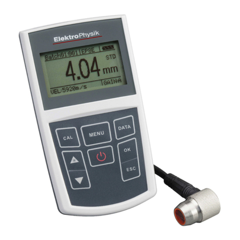
ElektroPhysik MiniTest 7200 FH Technical Document

Technical Manual /Operating Instructions
MiniTest 7200 FH / MiniTest 7400 FH
Thickness Gauges

Contents
© ElektroPhysik MiniTest 7200 FH / MiniTest 7400 FH
2
Contents
1. INTRODUCTION..........................................................................................................................5
2. FIRST STEPS.................................................................................................................................6
2.1 INSERT BATTERIES AND CONNECT SENSOR .................................................................................6
2.2 SWITCH ON AND TAKE READINGS..............................................................................................7
2.2.1 Setting language..................................................................................................................7
3. DESCRIPTION OF THE MEASURING SYSTEM...................................................................9
3.1 BASIC UNIT .................................................................................................................................9
3.1.1 General Remarks.................................................................................................................9
3.1.2 Operating keys ....................................................................................................................9
3.1.3 Sockets and interfaces.......................................................................................................10
3.1.4 Power supply.....................................................................................................................10
3.1.4.1 Batteries and storage batteries......................................................................................10
3.1.4.2 Power supply unit...........................................................................................................11
3.2 SENSORS FH 4 AND FH 10........................................................................................................11
3.2.1 General Remarks...............................................................................................................11
3.2.2 Sensor Models...................................................................................................................11
3.2.3 Sensor Stand......................................................................................................................12
4. THE USER MENU.........................................................................................................................13
4.1 G
ENERAL
R
EMARKS
....................................................................................................................13
4.2 S
WITCH
-ON / S
TART
S
CREEN
......................................................................................................13
4.3 MEASURE SCREEN /STATISTICS SCREENS ..................................................................................13
4.3.1 Measure Mode – Numerical Screen..................................................................................13
4.3.2 Measure Mode –Graphics Screen with MiniTest 7400 FH ..............................................14
4.3.3 Statistics Screens...............................................................................................................14
4.4 USER MENU ..............................................................................................................................15
4.4.1 USER PREFERENCES...............................................................................................................15
4.4.2 NUMERICAL ENTRIES.............................................................................................................16
4.4.3 ALPHANUMERICAL ENTRIES (ON MINITEST 7400 FH)...........................................................16
5. MEASURE MODE......................................................................................................................17
5.1 IMPORTANT NOTES ON THICKNESS MEASUREMENT..................................................................17
5.1.1 Limitations to magneto-static thickness measurement......................................................17
5.2 BATCH CONFIGURATION / NECESSARY SETTINGS.....................................................................17
5.2.1 Batch .................................................................................................................................17
5.2.2 Target Ball Size.................................................................................................................18
5.2.3 Data Logging Mode..........................................................................................................18
5.3 PREPARING MEASUREMENT......................................................................................................18
5.3.1 Calibration........................................................................................................................18
5.3.2 Measurement without Sensor Stand..................................................................................19
5.3.3 Using the Sensor Stand.....................................................................................................19
5.4 TAKE READINGS .......................................................................................................................19
5.4.1 Measurement without Sensor Stand..................................................................................19
5.4.2 Using the sensor stand......................................................................................................20
5.4.3 Delete Readings ................................................................................................................20
5.5 STORING READINGS INTO STATISTICS MEMORY .......................................................................20
5.5.1 Data Logging Mode..........................................................................................................20
5.5.2 Manual Data Storage........................................................................................................21

Contents
© ElektroPhysik MiniTest 7200 FH / MiniTest 7400 FH
3
5.5.3 Automatic Data Storage (Auto).........................................................................................21
5.5.4 Storing Minimum Reading................................................................................................21
5.5.5 Storing Maximum Reading................................................................................................21
5.6.1 Correct Sensor Position....................................................................................................22
5.6.2. Incorrect Readings through tilting of the Sensor.............................................................22
5.6.3 Incorrect readings through Blocked Target Ball..............................................................23
5.6.4 Air gap...............................................................................................................................23
5.6.5 Measuring material with ferruginous particles................................................................23
6. CALIBRATION...........................................................................................................................24
6.1 GENERAL REMARKS ON CALIBRATION .....................................................................................24
6.2 CALIBRATION METHODS............................................................................................................25
6.3 HOW TO CALIBRATE..................................................................................................................26
6.3.1 Factory Calibration ..........................................................................................................26
6.3.2 Zero only...........................................................................................................................26
6.3.3 Multi-point calibration (Zero + 1 to 4 point(s) )..............................................................27
6.4. DELETE CALIBRATION POINT....................................................................................................28
6.5 CALIBRATION ERROR SOURCES ................................................................................................29
7. DATA STORAGE........................................................................................................................30
7.1 BATCHES...................................................................................................................................30
7.1.1 General..............................................................................................................................30
7.1.2 Batch Data ........................................................................................................................30
7.2 DATABASE OF THE MINITEST 7400 FH.....................................................................................31
7.2.1 General Remarks...............................................................................................................31
7.2.2 Tree structure....................................................................................................................31
7.2.3 Create a Directory............................................................................................................31
7.2.4 Create a New Batch ..........................................................................................................32
7.2.5 Select a Batch for Measurement .......................................................................................32
7.2.6 Delete a Batch / a Directory .............................................................................................33
7.2.7 Rename a Batch / Rename a Directory.............................................................................33
8. STATISTICS................................................................................................................................34
8.1 STATISTICAL PARAMETERS.......................................................................................................34
8.1.1 Upper and lower specifications limits (USL and LSL).....................................................34
8.1.2 Set Point (Differential Mode)............................................................................................35
8.2 READINGS .................................................................................................................................35
8.2.1 View Readings...................................................................................................................35
8.2.2 Delete Single Readings .....................................................................................................35
8.2.3 Delete all Readings...........................................................................................................36
8.3 NUMERICAL STATISTICS ...........................................................................................................36
8.4 HISTOGRAM ON MINITEST 7400 FH .........................................................................................37
8.5 TREND DIAGRAM ON MINITEST 7400 FH.................................................................................37
9. DATA OUTPUT / DATA TRANSFER......................................................................................38
9.1 D
ATA
P
RINT
-O
UT
........................................................................................................................38
9.1.1 Screen Shot........................................................................................................................39
9.1.2 Print-out a Batch...............................................................................................................39
9.2 TRANSFER DATA TO A PC.........................................................................................................40
10. MAIN MENU .............................................................................................................................41
10.1 DATABASE ..............................................................................................................................41

Contents
© ElektroPhysik MiniTest 7200 FH / MiniTest 7400 FH
4
10.2 STATISTICS..............................................................................................................................41
10.3 CALIBRATION..........................................................................................................................41
10.4 ACTIVE BATCH .......................................................................................................................41
10.4.1 Batch Properties .............................................................................................................41
10.4.2 Readings..........................................................................................................................42
10.4.3 Configuration..................................................................................................................42
10.4.4 Calibration......................................................................................................................42
10.5 S
ETUP
.......................................................................................................................................43
10.5.1 General Remarks.............................................................................................................43
10.5.2 Display............................................................................................................................43
10.5.3 Date and Time.................................................................................................................43
10.5.4 Data Outputs...................................................................................................................44
10.5.5 User Preferences.............................................................................................................45
10.5.6 Gauge Specifications.......................................................................................................45
11. SPECIAL FUNCTIONS............................................................................................................46
11.1 INITIALIZING ...........................................................................................................................46
11.2 S
PECIAL FUNCTIONS
..................................................................................................................47
12. QUICK REFERENCE ..............................................................................................................48
13. CARE AND MAINTENANCE.................................................................................................49
13.1 CARE.......................................................................................................................................49
13.1.1 Using NiMH storage batteries........................................................................................49
13.2 M
AINTENANCE
.....................................................................................................................49
14. TECHNICAL SPECIFICATION.............................................................................................50
14.1 G
AUGE AND
S
ENSOR
S
PECIFICATION
..........................................................................................50
14.2 DELIVERY SCHEDULE .............................................................................................................52
14.2.1 Thickness gauge MiniTest 7200 FH / 7400 FH..............................................................52
14.2.2 Sensors............................................................................................................................52
14.3 ACCESSORIES..........................................................................................................................53
15. APPENDIX.................................................................................................................................56
15.1 T
ROUBLESHOOTING
...................................................................................................................56
15.2 D
ETECTION OF
E
RROR SOURCES
(INF
FLAG
)...............................................................................59
15.3 STATISTICAL TERMS ...............................................................................................................60
15.4 SAFETY NOTES........................................................................................................................62
15.5 D
ECLARATION OF
C
ONFORMITY
.................................................................................................64
15.6 A
FTER
S
ALES
S
ERVICE
..............................................................................................................65
INDEX...............................................................................................................................................66

© ElektroPhysik MiniTest 7200 FH / MiniTest 7400 FH
5
1. Introduction
Designed for non-destructive thickness measurement, the portable MiniTest 7200 / 7400 FH
measuring systems are suitable for in the field or laboratory use. Working on the magneto-static
principle, the gauges enable quick and easy measurement on non-ferromagnetic materials.
The measuring system consists of a handy sensor, which is connected via a cable to the base and
display unit for visualization and processing of readings. For measurement, specially treated target
balls made of a ferromagnetic material are used as a reference. For measurement, a target ball is
placed on the material to be measured so that the material thickness between target ball and
sensor will be measured. The measuring system comes with sensor stand (available as an option)
to add additional comfort of handling during measurement.
For documentation a portable data printer is available. The measuring system may also be
connected to a PC for data communication.
For taking readings, the sensor is placed on the surface of the measuring object, the target ball is
placed on the opposite side of sample. The sensor is placed on the opposite side of sample.
Equipped with a strong permanent magnet, the sensor attracts the target ball and holds it exactly
over its sensor tip. When moving the sensor, the target follows accordingly. The presence of the
target ball will change the magnetic field near the sensor tip. The magnetic field changes according
to the distance between target ball and sensor tip. The change of magnetic field increases with the
distance between target ball and sensor tip getting smaller and can be taken as a reference for the
material thickness of the sample to be measured. The sensor incorporates a Hall element to
capture the change of magnetic field and to translate it into thickness.
For measuring hollow parts, a target ball is placed into the interior of sample and the sensor is
placed on the opposite side in order to attract the target ball exactly over the sensor tip. For taking
readings, the sensor is moved over the surface of sample. For measuring sheets, the sensor is
placed on the surface of sheet and the target ball is placed near the sensor on the opposite side of
sheet. The target ball will automatically center on the correct measuring position and the
measuring processes can be started.
For measuring large-sized parts, the sensor can be guided manually over the sample to be
measured. For measuring small parts, it is recommended to use the sensor stand supplied with the
sensor.
Suitable for use in industrial production areas, the measuring systems MiniTest 7200 / 7400 FH
measure hollow parts, containers and sheet material of all kinds such as bottles, cans, injections
moldings, car bodies, glass, SMC components etc made of non-magnetic (non-ferrite) materials.

© ElektroPhysik MiniTest 7200 FH / MiniTest 7400 FH
6
2. First Steps
This section refers to persons to use the gauge for the first time. This section explains the main
features of the gauge and how to take readings.
2.1 Insert Batteries and connect Sensor
a) Take gauge and batteries from the carrying case.
b) Push the battery compartment lid at the gauge bottom in arrow direction (as shown below)
c) Insert batteries into the battery compartment. Respect polarities (as shown below).
d) Close lid.
b) c)
e) Take requested sensor (FH4 or FH10) form the carrying case. Plug sensor into the socket on
top of the base unit (as shown below). Make sure the nib of plug is correctly inserted into the
guide way of socket. The red marking at the probe plug must be positioned correctly to the red
marking at the sensor plug.
f) Fully engage the sensor plug into the sensor socket to the stop.
Sensor Socket

© ElektroPhysik MiniTest 7200 FH / MiniTest 7400 FH
7
2.2 Switch ON and Take Readings
2.2.1 Setting language
This setting can be made at initial use or as requested at any time (see section 11.1)
Press the red ON/OFF button on the left side of gauge and ESC simultaneously to switch on and to
go to initialization menu.
1. A banner appears with a language option.
User arrow keys ↑↓ to go to your requested language option.
Press OK to confirm or ESC to abort.
2. On display appears “Total Reset”. A Total Reset restores factory settings. To abort Total
Reset, press Function key “No” (section 11.1)
a) Start Screen appears showing company logo, gauge version
and sensor type that is currently connected (see illustr. on the
left.
b) After approx. 2 seconds, the gauge switches automatically into
measure mode and is ready to take readings. The Measure
Screen will appear without any reading being shown.
c) At initial switch-on the gauge is in “Direct Mode“ (see section
7.1.1). For this mode, the factory calibration is preset (for more
detailed information on “Calibration” topics please refer to section
6). The Status Line provides information on the active calibration
method and the active batch (MiniTest 7400 FH) Please check
whether the target ball size as adjusted matches your application
(for more details on target ball size pleaser refer to section 5.2.2
“Target ball size”).
Flashing antenna symbol if sensor is
connected
Selected calibration mode, here:
Zero calibration
Target ball diameter, hiere: 4.0 mm.
Active batch, here: Pet bottle
(only with Minitest 7400 FH)
Status line

© ElektroPhysik MiniTest 7200 FH / MiniTest 7400 FH
8
d) The factory calibration is for quick and easy measurement when larger measuring errors are
acceptable. For other calibration methods please refer to section 6.2.
e) For measurement, please use the sensor stand supplied with the gauge. Place the measuring
object on the sensor. Place the target ball on the opposite side. For measuring hollow parts,
place the ball inside the sample. Equipped with a strong permanent magnet, the sensor attracts
the target ball and holds it exactly over its sensor tip. Hold the measuring object in rectangular
position to the sensor and move it smoothly over the sensor. Press OK to store the reading into
memory. Press Function key “Statistics” to view readings and the numerical statistics.
For measuring large-sized sheeting material or large hollow parts, place the senor on the
surface of sample. The target ball is placed on the opposite side near the sensor. Keep the
sensor in rectangular position to the surface and move it across the surface of sample.

© ElektroPhysik MiniTest 7200 FH / MiniTest 7400 FH
9
3. Description of the measuring system
3.1 Basic unit
3.1.1 General Remarks
3.1.2 Operating keys
Use the ON/OFF button to switch the gauge ON or OFF. If you press ON/OFF button and ESC
simultaneously, the initializing procedure will be performed (for more details please refer to section
11.1).
The Function keys may assume different functions according to the menu being active. Their
current properties are displayed in the line upper to the Function keys.
The command and navigation key block may also assume different functions:
-
Press OK to confirm settings, store values or select menu items.
-
Press ESC to abort actions or to quit submenus.
-
Use ARROW keys to navigate through the menu or change settings.
-
If the alphanumerical block has been activated, OK and ESC keys also assume navigation
functions.
The Function keys and the command and navigation key block may be backlit on request. This
adds additional comfort in poor light conditions (for more details please refer to section 10.5.2)
Function keys
ON/OFF button
Command and
navigation key
block
Graphics display
160 x 160 Dots
Large backlit display for easy reading of
measuring values, statistical data, histogram and
trend diagram.
Robust scratch resistant plastics housing.

© ElektroPhysik MiniTest 7200 FH / MiniTest 7400 FH
10
Press the “Help” Function key for calling the context-oriented on-line “Help“.
3.1.3 Sockets and interfaces
The basic unit features a sensor socket for connecting the FH 4 or the FH 10 sensor. The multi-
purpose socket is used for connecting the mains unit, the foot switch, the alarm device or the
RS232 interface cable.
3.1.4 Power supply
3.1.4.1 Batteries and storage batteries
Both models, MiniTest 7400 FH and MiniTest 7200 FH, are powered by a set of four alkaline-
manganese cells, 1.5V, AA LR6 size (Batteries included in the standard supply schedule.).
As an alternative, both models may be operated on rechargeable NiMH (type AA-HR6) storage
batteries or via a power supply unit (available as an option). Please use only products as
recommended by ElektroPhysik (See section 14.3, Accessories).
If you wish to use the storage batteries, they must be recharge using the external charger unit
(available as an option). Please also refer to section 13.1 “Care and maintenance” for more details.
Note:
• Remove batteries or storage batteries from the instrument if you are not going to use it for a
longer period of time.
• The battery symbol on display indicates the battery state.
• For field use, replacement batteries should be made available.
• Erratic readings due to low battery voltage do not occur because the gauge switches off or
does not switch on if the battery is too low.
Multi-purpose socket Sensor socket
IR Interface

© ElektroPhysik MiniTest 7200 FH / MiniTest 7400 FH
11
• Used or defective batteries or storage batteries may contain hazardous substances and
must be disposed according to the legal provisions of your country.
3.1.4.2 Power supply unit
For mains operation, the power supply unit must be used. If operated via the power supply unit,
batteries should be inserted to supply the internal time clock, otherwise, after approx. 1 minute, the
settings of the real-time clock will go lost as soon as supply from the mains is cut.
The power supply unit comes with two different adapter plug versions (Euro and US plug). If the
power supply unit comes with an adapter plug connected that does not match your socket, simply
change the adapter plug accordingly.
Simply remove the adapter from the power supply unit and fix the other one as required.
Note:
The adapter has not been designed for frequent change.
3.2 Sensors FH 4 and FH 10
3.2.1 General Remarks
In this new SIDSP (Sensor integrated digital signal processing) procedure, all necessary
measuring signals are created and completely processed in the sensor itself. Only the completely
processed digital readings are transferred to the base unit for display, statistical evaluation and
data storage. Unlike the commonly used analog procedures, the new SIDSP procedure excludes
any error influences on the measuring data during transfer over the probe cable. The result is a
measuring accuracy and constancy of readings that has been unmatched so far. The complete
sensor technique is integrated into a robust stainless-steel housing.
3.2.2 Sensor Models
Two sensor models are available:
-
FH 4 sensor to cover the 0 …4 mm range
-
FH 10 sensor to cover the 0…10 mm range.
Both sensors feature a wear-resistant sensor tip most suitable also for hard materials such as
glass, for instance.

© ElektroPhysik MiniTest 7200 FH / MiniTest 7400 FH
12
3.2.3 Sensor Stand
Both sensor types come with a spring-loaded V-grooved sensor stand. The use of the sensor stand
ensures increased reproducibility of readings by adding stability of the sensor during measurement
so that even small parts can be measured without problems.

© ElektroPhysik MiniTest 7200 FH / MiniTest 7400 FH
13
4. The User Menu
4.1 General Remarks
4.2 Switch-ON / Start Screen
At switch on, the company logo, gauge version and type of sensor being connected appear on
display.
After approx. 2 seconds the gauge switches to the measure screen of the last batch that was
active before the gauge was switched off.
4.3 Measure screen /Statistics screens
Readings can be displayed numerically only or numerically combined with a diagram (only with
MiniTest 7400 FH)
4.3.1 Measure Mode – Numerical Screen
Target ball size and measuring unit
Power supply indicator
Time clock
Adjusted set point
Current reading
CALIBRATION MODE
Number of readings
The current
function key
proper-
ties
are indicated in the line above the
function keys.
Active batch (MiniTest 7400FH only)
Minimum reading
Maximum reading
Status line

© ElektroPhysik MiniTest 7200 FH / MiniTest 7400 FH
14
4.3.2 Measure Mode –Graphics Screen with MiniTest 7400 FH
For setting the Real-Time Trend display option, select “Active Batch” form the Main Menu. Press
OK to confirm. Select “Configuration” from the Batch Menu and press OK to confirm. Use the arrow
keys to move to the “Graphics” option. ON or OFF is highlighted. Use arrow keys to make your
selection and press OK to confirm or the “ESC” navigation button to restore previous setting and to
go back to the previous menu level.
To take full advantage of the real-time trend it is necessary to tolerance limits (see also section
8.11 „Upper specification limits (USL) and lower specification limits (LSL)“.
4.3.3 Statistics Screens
,
Target ball size, measuring unit
DATA LOGGING MODE
Power supply indicator
Time clock
Reading
NAME OF ACTIVE BATCH
⇓
LOWER LIMIT
⇑
UPPER LIMIT
CALIBRATION METHOD
MAX = MAXIMUM READING
MINIMUM READING
N = NUMBER OF READINGS
REAL
-
TIME TREND
Set point
The current
function key
proper-
ties
are indicated in the line above the
function keys.
STATUS LINE
The current
function key
proper-
ties
are indicated in the line above the
function keys.
Power supply indicator
Time clock
Process capability,
cp and cpk
Selected calibration mode
Active batch
(MiniTest 7400 FH only)

© ElektroPhysik MiniTest 7200 FH / MiniTest 7400 FH
15
4.4 User Menu
The numerous MiniTest FH 7400 / 7200 features can be accessed via the different menus that are
divided into submenus.
Press the Function key “Main menu“ in order to get access to the main menu.
Select an item from the Main Menu (e.g. Database) and press OK to confirm. You will go to a
submenu. Use the arrow keys to select the requested item and press OK to confirm.
To go back to the previous menu level press ESC.
According selected submenu you can
-
View settings (e.g. Gauge specs = Gauge specifications in the Setup Menu)
-
Select preset parameters (e.g. 100% brightness from the Display Menu)
-
Make numerical or alphanumerical entries (e.g. Enter a directory name in the database / new
directory option).
4.4.1 User Preferences
Use the arrow keys to select your requested menu item, e.g. Language.
Press OK to confirm. The current selection will be highlighted. Use the
arrows to select the requested parameter (e.g. English) and press OK to
confirm. To undo your selection, press ESC and you will return to the
previous menu level.

© ElektroPhysik MiniTest 7200 FH / MiniTest 7400 FH
16
4.4.2 Numerical Entries
As soon as the alphanumeric block is activated, ESC and OK will
assume navigation functions to the left or right. Choose your character
by placing the cursor over the requested character. After a certain period
of time, the entry will be accepted automatically without the need to
confirm. This period of time can be specified under User Preferences in
the “Entry accepted” option. See also section 10.5.5 for further
reference. Complete your entry by pressing Function key “Ready” and
then confirm “Save changes?” by pressing OK.
4.4.3 Alphanumerical Entries (on MiniTest 7400 FH)
For alphanumerical entries you can use as many as 15 characters for
entering a name. ESC and OK assume navigation functions to the left or
right. Choose your character via the alphanumerical block. Your
selection will be automatically accepted after the previously specified
period of time. This period of time can be set under User Preferences in
the “Entry accepted” option. See also section 10.5.5 for further
reference. Complete your entry by pressing Function key “Ready”.
Complete your entry by pressing Function key “Ready” and then confirm
“Save changes?” by pressing OK.

© ElektroPhysik MiniTest 7200 FH / MiniTest 7400 FH
17
5. Measure Mode
5.1 Important Notes on Thickness Measurement
Make sure that the operator has been properly instructed regarding the use of thickness gauges
and has basic knowledge of the specific requirements for measurement of the application. The
operator should have basic knowledge of the following:
• Selection of a measuring device suitable for his application
• Fundamentals on the magneto-static measuring principle
• Influences on the magnetic fields through the surrounding field
• Influence of the surface properties of the material to be tested (roughness, build-up on the
surface)
• Statistical evaluation of measuring series
• Gravity influencing the reference ball
5.1.1 Limitations to magneto-static thickness measurement
The information obtained from thickness measurements according to the magneto-static principle
only refer to those parts of the test object that have been covered by the magnetic sensor. For that
reason, be careful to draw conclusion on other parts of the measuring object that have not been
covered by the sensor during measurement. In general, such conclusions are only admissible if
comprehensive experience and approved methods of statistical data acquisition are available.
5.2 Batch Configuration / Necessary Settings
Before taking readings, it is necessary to make a few settings in the Configuration menu. The
Configuration always refers to a certain measuring series (Batch).
5.2.1 Batch
-
You can continue to take readings in the active batch
-
You can create a new batch (only with MiniTest 7400 FH model)
-
You can choose an exiting batch from the database (please refer to section 7.2).

© ElektroPhysik MiniTest 7200 FH / MiniTest 7400 FH
18
5.2.2 Target Ball Size
According to sensor type and the shape of measuring object, a
suitable target ball must be set. This can be made in the Configuration
menu, menu item “Target ball” (also refer to section 6 “Calibration”.
Use arrow keys to move to “Target Ball” size and press OK. Use arrow
keys to adjust the requested target ball size. Press OK to confirm your
setting or press ESC to undo your setting. If you undo, you will
automatically quit tar
get ball setting option and go back to the previous
menu level.
5.2.3 Data Logging Mode
In the data logging mode you can specify how you wish readings to be stored in memory. Several
modes are available:
-
manually or via footswitch (Current reading, MIN, MAX)
-
Automatic (Auto)
Note: For logging data into memory please always proceed as follows: Put the sensor into the
correct measuring position, press ESC. Then readings can be taken.
5.3 Preparing Measurement
Before measurement, the probe must be adapted to the ambient temperature. In case of high
variations in temperature, the target ball must be lifted from the probe tip at regular intervals (e.g.
every other minute). This is to compensate for frequency drift due to variations in temperature. It is
recommended to switch on the gauge for warming up around 2 to 3 minutes in order to ensure
maximum measuring accuracy.
5.3.1 Calibration
According to your setting of task, you may use different calibration methods. Measuring accuracy
depends on the selected calibration method. Please refer to section 6 for more details on this
issue.
There are three calibration methods available:
-
Factory
-
Zero only
-
Multi-point calibration (Zero + 1 to 4 Point(s)

© ElektroPhysik MiniTest 7200 FH / MiniTest 7400 FH
19
5.3.2 Measurement without Sensor Stand
For measuring large-sized parts, the sensor can be guided manually over the measuring sample.
For measuring thick samples (6 mm and thicker) make sure to keep the sensor in vertical position
to the sample. When holding the sensor in horizontal position, due to the influence of gravity on the
steel ball, the readings will be higher than the actual thickness.
5.3.3 Using the Sensor Stand
For measuring small parts, bottles or other cylindrical bodies the sensor stand (supplied with the
sensor) and a footswitch (available as an option) should be used.
Put the sensor into the stand and secure with the red sensor stand
retaining ring.
5.4 Take Readings
5.4.1 Measurement without Sensor Stand
For measurements on large-sized sheeting material or large hollow parts, place the sensor onto
the surface of the object to be measured. Place an appropriate target ball on the opposite side of
object near the sensor. The target ball will be attracted by the strong permanent magnet of sensor
and be positioned centrally just opposite of the sensor tip. Keep the sensor in right-angle position
to the object to be measured and scan continuously over the surface. For storing readings, please
refer to section 5.5.1.

© ElektroPhysik MiniTest 7200 FH / MiniTest 7400 FH
20
5.4.2 Using the sensor stand
If you are using the sensor stand, position the sample on the sensor tip and keep it in right-angle
position to the sensor. Place the appropriate target ball on the opposite side of object. Make sure
to keep the right-angle position while moving the object continuously over the sensor. For storing
readings, please refer to section 5.5.1.
When measuring small hollow parts such as bottles e.g., put the target ball inside the object and
place the object onto the v-grooved device of sensor stand. Turn the object until the target ball is
centered directly over the sensor tip. Then move the object continuously over the v-groove of
sensor stand. For storing readings, please refer to section 5.5.1.
5.4.3 Delete Readings
Please refer to section 8.2.2 “Delete Single Readings“.
5.5 Storing Readings into Statistics Memory
5.5.1 Data Logging Mode
During measurement, readings can be stored into memory manually or automatically. Data in
memory will be used for statistics.
The following storing options are available:
-
Storing the current reading manually or automatically
-
Storing the minimum reading (only manually)
-
Storing the maximum reading (only manually).
The Data logging mode can be specified in the “Configuration” submenu. Use arrow keys to select
the Data logging mode option and press OK to confirm. You can chose from the following setting
options:
-
Curr. reading (Current reading)
-
Auto
-
Max
-
Min
Make your selection and press OK to confirm. If you wish to undo your setting (before OK has
been pressed) press ESC and the gauge will return to the previous menu level.
This manual suits for next models
1
Table of contents
Other ElektroPhysik Measuring Instrument manuals

ElektroPhysik
ElektroPhysik SmarTest User manual

ElektroPhysik
ElektroPhysik MiniTest 700 Manual
ElektroPhysik
ElektroPhysik MiniTest 430 Use and care manual

ElektroPhysik
ElektroPhysik MiniTest 4500 User manual

ElektroPhysik
ElektroPhysik MiniTest 403 Use and care manual
ElektroPhysik
ElektroPhysik MiniTest 725 Technical Document

ElektroPhysik
ElektroPhysik QuintSonic 7 Technical Document
ElektroPhysik
ElektroPhysik MiniTest 440 Use and care manual

ElektroPhysik
ElektroPhysik MiniTest 430 Technical Document

