KAM PowerGlide User manual

XY Laser
MANUAL VERSION 1.0
0 5 - 11-14
For the latest instruction manual updates and information on the entire Kam range visit:
www.kam.co.uk
Kam products are manufactured by: Lamba plc, Unit 1, Southfields Road, Dunstable, Bedfordshire, United Kingdom LU6 3EJ
Telephone: (+44) (0)1582 690600 • Fax: (+44) (0)1582 690400 • Email: [email protected] • Web: www.lambaplc.com
If this product is ever no longer functional please take it to a recycling plant for environmentally friendly disposal.
Due to continuous product development, specifications and appearance are subject to change.
© Copyright Lamba plc. E&OE.
PowerGlide
Multicolour sweeping beam effects

Thank you for purchasing this Kam product, we are sure that it will serve you for many years to come.
To optimise it’s performance, please read these instructions carefully to familiarise yourself with the basic operations of the unit.
Please retain them for future reference.This unit has been tested at the factory before being shipped to you. To prevent or reduce
the risk of electrical shock or fire, do not expose the unit to rain or moisture. To prevent a fire hazard, do not expose the unit to
any naked flame sources. Unplug this apparatus during lightning storms or if it is unlikely to be used for long periods of time.
When installing the unit, please ensure you leave enough space around the unit for ventilation. Slots and openings in the unit are
provided for ventilation to ensure reliable operation of the product and to protect it from overheating. To prevent fire hazard, the
openings should never be blocked or covered.
The unit is powered by the mains, always handle the power cable by the plug. Never pull out the plug by pulling on the cable.
Never touch the power cable when your hands are wet as this could cause an electric shock. Do not tie a knot in the cable. The
power cable should be placed such that it is not likely to be stepped on. A damaged power cable can cause a fire or give you an
electrical shock. Check the power cord periodicaly, if you ever find that it is damaged, replace it before using the unit again.
Contact your retailer for a replacement.
The voltage of the available power supply differs according to country or region. Be sure that the power supply voltage of the area
where this unit is to be used meets the requirements of the unit.
The lightning flash symbol inside a triangle is to alert the user to the presence high voltage within the unit’s enclosure
that may be of sufficient power to constitute a risk of electrical shock to persons. Caution: to prevent the risk of electric
shock, do not attempt to open the unit. No user-serviceable parts inside. Refer all servicing to qualified service
personnel. The exclamation mark inside a triangle is intended to alert the user to the presence of important operating
and maintenance instructions in the literature accompanying the appliance. Please read and pay attention to all laser
safety warning sticker labels on the unit.
Select the installation location of your unit carefully. Avoid placing it in direct sunlight or locations subject to vibration and
excessive dust. Do not use the unit where there are extremes in temperature (below 41ºF / 5ºC or exceeding 95ºF / 35ºC).
Unpacking and safety Please unpack your new product carefully. Your new product should reach you in perfect condition.
Please check that no damage has occurred during transit. If any damage is found, do not operate your unit. Please contact the
retailer you purchased it from immediately. If there is any damage to the mains cable do not use the device. Always disconnect
the unit from the mains supply when carrying out any cleaning of the unit.
Manufacturer declarations
In compliance with the following requirements: RoHS Directive (2002/95/EU) and WEEE Directive (2002/96/EU).
If this product is ever no longer functional please take it to a recycling plant for environmentally friendly disposal.
CE declaration of conformity
R&TTE Directive (1999/5/EU), EMC Directive (2004/108/EU), Low Voltage Directive (2006/95/EU).
Before putting the devices into operation, please observe the respective country-specific regulations.
AC power
The unit is supplied with a power plug appropriate to its voltage. Should any other connections be required they must be carried
out with the following configuration:
Cable (EU)
Cable (US)
Pin
International
Brown
Black
Live
L
Light blue
White
Neutral
N
Yellow/green
Green
Earth

DMX-512 connection
If you are using a standard DMX controller, you can connect the DMX output of the controller directly to the DMX input of the first
unit in a DMX chain. If you wish to connect a DMX controller with other XLR outputs you will need to use adapter cables.
1 = ground 2 = minus signal (-) 3 = plus signal (+)
Connect the DMX output of the first unit in a DMX chain with the DMX input of the next unit in the chain. Always connect the the
output of one unit with the input of the next unit until all units are connected. If you use a controller with 5 pin DMX connection you
will need to use a 5 pin to 3 pin adapter.
Overhead rigging
Important - the installation must be carried out by qualified service personal only. Improper installation can result in serious
injuries and /or damage to property. Overhead rigging required extensive experience. Working load limits should be respected,
certified installation materials should be used, the installed unit should be inspected regularly for safety.
!Make sure the area below the installation place is free from unwanted persons during rigging, de-rigging and servicing.
!Locate the unit in a well ventilated spot, far away from any flammable materials and/or liquids. The fixture must be fixed at
least 50cm from surrounding walls
!The device should be installed out of reach of people and outside of areas where persons may walk by or be seated.
!Before rigging make sure that the installation area can hold minimum point load of 10 times the device’s weight.
!The device should be well fixed; a free swinging mounting is dangerous.
!Do not cover any ventilation opening as this may result in overheating
Before first time use, the unit should be inspected for safety. Inspection the unit regularly every year.
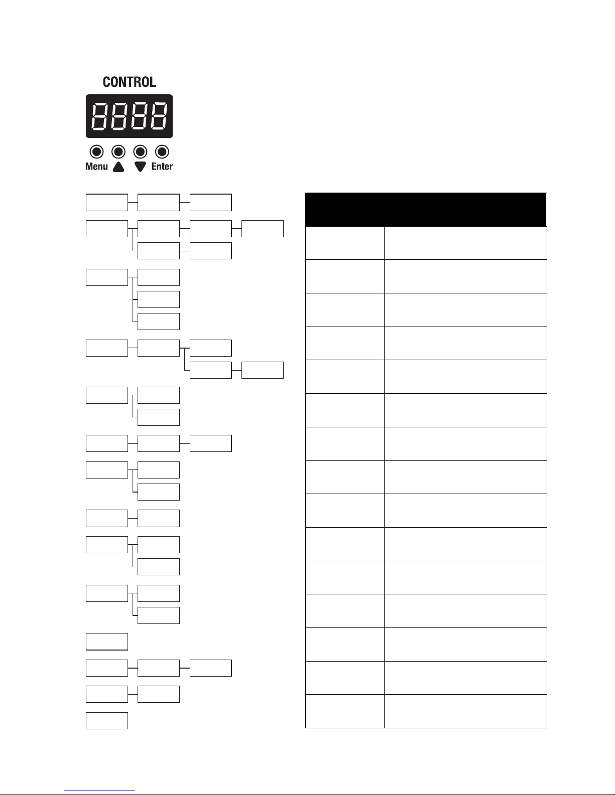
Quick Start Guide
After connecting your unit to the mains, use the Control menu on the side panel of the unit to set the operating mode.
Use the MENU button to make a function selection, then press ENTER to confirm it. Next use the UP and DOWN arrow buttons
to refine your selection, then use the ENTER button to confirm your setting.
Running the unit in Auto Show mode
Use the side panel Control menu to find and select the Shnd mode and the ENTER button to confirm.
Use the UP and DOWN arrow buttons to select your chosen show (Sh0-sh16) and then press ENTER to confirm your choice.
You can set the speed of the show using the UP and DOWN arrow buttons (Sp1-sp9).
Press the MENU button again to return to the main menu.
Running the unit in Sound-to-Light mode
Use the side panel Control menu to find and select the SoUd mode then the ENTER button to confirm. Next choose on or
off then the ENTER button to confirm. If you have chosen ON, the unit will now respond to music via the built-in microphone.
To adjust the sensitivity of the microphone, choose Sens, then the ENTER button to confirm. Use the UP and DOWN arrow
buttons to set the sensitivity value from 0 to 100, then press the ENTER button to confirm your choice.
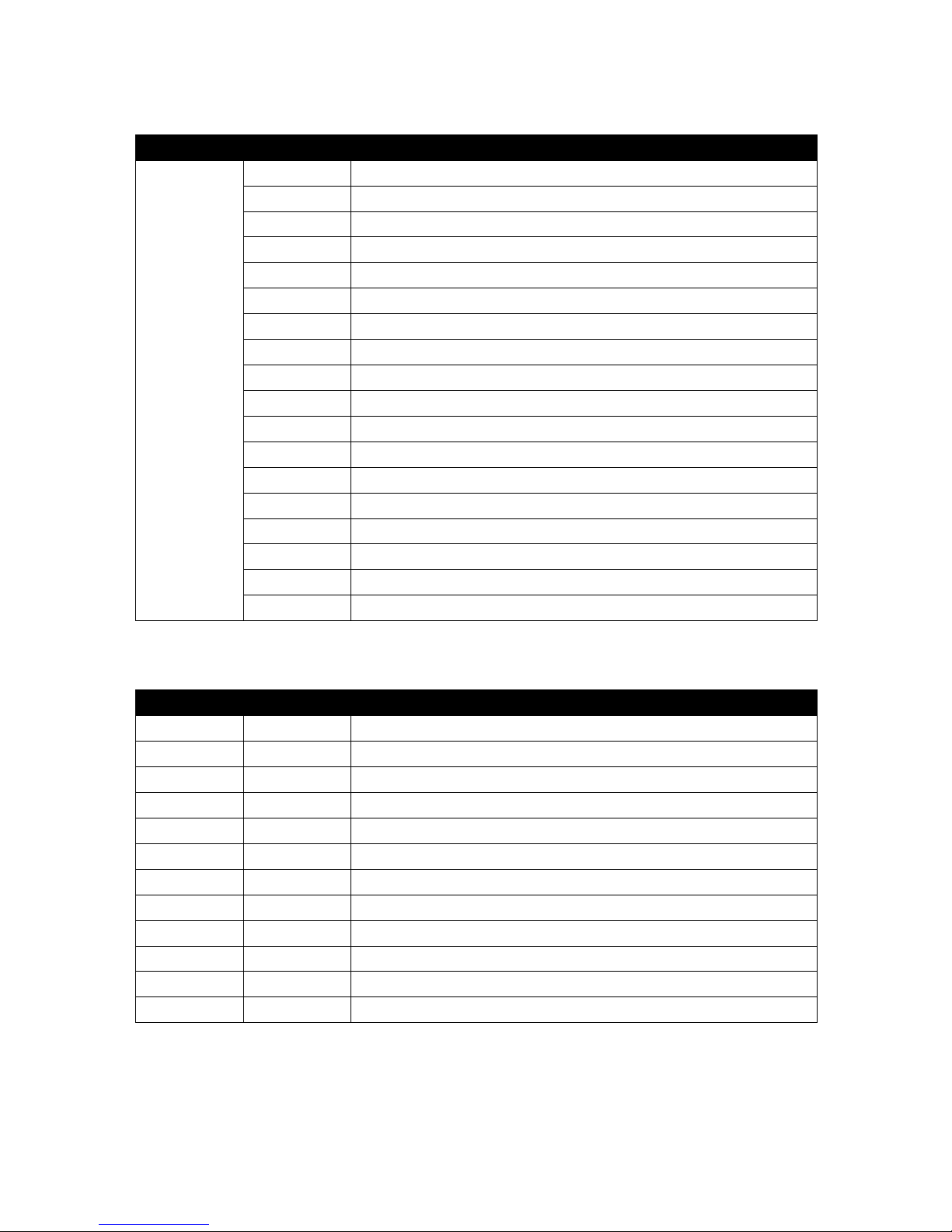
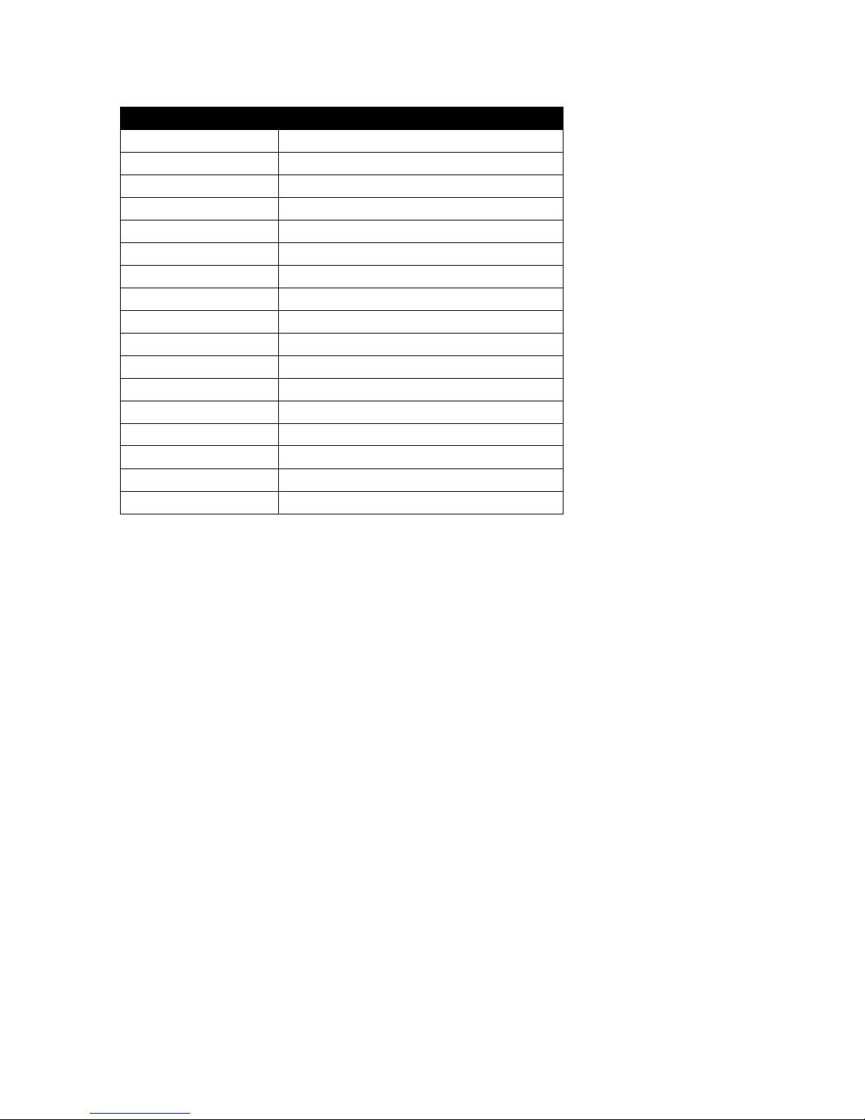
Running the unit in DMX mode
If you intend to control the unit via DMX, you will need to set the DMX address correctly. Choose Addr then ENTER to confirm.
Use the UP and DOWN arrow buttons to set the address number and then press ENTER to confirm your choice.
The unit can run in different channel modes. Choose ChNd then ENTER to confirm. Use the UP and DOWN arrow buttons to
choose between 1, 6, 8, 12 or 18 channel modes and then press ENTER to confirm your choice. Press the MENU button again to
return to the main menu.
Running the unit in Master/Slave mode
Connect multiple units with DMX cables running from the DMX Output from one unit into the DMX Input of the next unit in the
chain. Set the first unit in the chain as the Master unit and set all others to Slave mode. The Slaves will then follow the Master.
To set up in Master/Slave mode, use the side panel Control menu to select SLND then NASt on the first (Master) unit.
Then select ShNd and choose a Show (Sh 0 to Sh16) then press ENTER to confirm your choice.
On all other units, select SLND then choose SL1 or SL2. then press ENTER to confirm your choice.
SL1 is normal Slave mode where all units follow the Master unit’s operation. Use the SL2 setting if you are only using two
units as this mode will make the Slave unit mirror the Master unit and create a better show.

Rear panel Control LED display
Addr A001 A512
ShNd sh 0
Sens 0 100
SoUn on
ChNd 1Ch
12Ch
SL 1
6Ch 8Ch
SL 2
18Ch
off
tlt1 no
Yes
dISp dSIP
led on
off
tlt2 no
Yes
test
hour 0
uer
rSet
u10
9999
SLNd NASt
sh16
sp 1 sp 9
Display
Function
Addr
Set the DMX address for the unit.
Use the Up and Down buttons to set.
ChNd
Set the DMX channel mode.
Choose from 1, 6, 8, 12 or 18 channels.
SLNd
Set the unit to Master/Slave mode.
Choose Master, Slave 1 or Slave 2.
ShNd
Set the unit to Show mode.
Set the pre-programmed show (from 01-16).
Sp1 –sp 9
Sets the speed of the show.
Speed setting from 1-9.
SoUn
Set the unit to Sound-to-Light mode.
Choose either On or Off.
Sens
Set the microphone sensitivity.
Choose from 0(low) to 100(high) sensitivity.
Led
Set the Control LED display to turn off
automatically (OFF) or remain on (ON).
dISP
Rotate the Control LED display 180°.
Use when unit is mounted upside down.
tLt1
Set the first row Y axis position.
Set the first row Y axis reverse position.
tLt2
Set the second row Y axis position.
Set the second row Y axis reverse position.
test
Set the unit to run through a series
of auto self tests.
hour
Unit runtime.
uer
Software version.
rset
Resets the unit.

1 channel DMX operation (choose A001 address)
12 channel DMX operation
Channel
Value
Function
CH1
(008-255
can also be
used with
Sound-to-Light)
000-007
No Function
008-022
Show 01
023-037
Show 02
038-052
Show 03
053-067
Show 04
068-082
Show 05
083-097
Show 06
098-112
Show 07
113-127
Show 08
128-142
Show 09
143-157
Show 10
158-172
Show 11
173-187
Show 12
188-202
Show 13
203-217
Show 14
218-232
Show 15
233-247
Show 16
248-255
Sound-to-Light mode
Channel
Value
Function
1
000-255
The first line. Y position
2
000-255
The second line. Y position
3
000-255
Full dimmer, 0-100%
4
000-255
Strobe, slow to fast
5
000-255
Colour 1
6
000-255
Colour 2
7
000-255
Colour 3
8
000-255
Colour 4
9
000-255
Colour 5
10
000-255
Colour 6
11
000-255
Colour 7
12
000-255
Colour 8

6 / 8 / 18 channel DMX operation
6 channel
8 channel
18 channel
Value
Function
1
1
1
000-255
Tilt 1 0 ~ 270 degrees
2
000-255
Tilt 1 Driver speed, fast to slow
2
3
000-255
Tilt 2 0 ~ 270 degrees
4
000-255
Tilt Driver speed, fast to slow
3
5
000-255
Full dimmer, 0-100%
2
4
6
000-008
No change
009-255
Strobe, slow to fast
7
000-008
No function
009-024
R
025-041
G
042-057
B
058-074
W
075-090
R+G
091-107
R+B
108-123
R+W
124-140
G+B
141-156
G+W
157-173
B+W
174-189
R+G+B
190-206
R+G+W
207-222
R+B+W
223-239
G+B+W
240-255
R+G+B+W
8
000-255
Colour 2
9
000-255
Colour 3
10
000-255
Colour 4
11
000-255
Colour 5
12
000-255
Colour 6
13
000-255
Colour 7
14
000-255
Colour 8
3
5
15
000-007
NO change
008-247
Show 1 – 16 optional
248-255
Sound mode
4
6
16
000-255
Show speed, slow to fast
5
6
17
000-014
NO change
015-255
Colour fade
6
8
18
000-255
Colour fade, slow to fast

Technical specifications
Kam PowerGlide
Mains power
AC 110-240V 50/60Hz
Mains connection
IEC mains input and output
Fuse
F7A L250V
Control modes
DMX512 / Auto / Sound-to-Light / Master/Slave
Light source
8 x 10w CREE 4-in-1 LED
Colours
Red, green, blue and white
Dimming
0 to 100%
Red lumi (1m)
7800 x 8 Lux
Green lumi (1m)
16100 x 8 Lux
Blue lumi (1m)
30000 x 8 Lux
White lumi (1m)
29300 x 8 Lux
Control setting
4 buttons plus function setting LED display
Operating temperature
10~40°
DMX512 connections
3 pins XLR input (male) and output (female)
DMX512 channels
1 / 6 / 8 / 12 / 18
Dimensions (WxDxH)
400 x 235 x 130mm (not inc brackets)
Nett weight
5Kg
Other KAM Floodlight manuals
Popular Floodlight manuals by other brands

Dialight
Dialight ProSite Installation & operation instructions

Chauvet DJ
Chauvet DJ EVE TF-20X user manual

brennenstuhl
brennenstuhl TORAN 3050 MB operating instructions

BEGA
BEGA 77 153 Instructions for use

VONROC
VONROC WL507AC Original instructions

Eye Lighting
Eye Lighting H566 Series Installation & maintenance