Kandolite K575POD818RGBW User manual

USER MANUAL
K575POD818RGBW

I n d e x
Summarize ......................................................................... 3
Safet instruction................................................................ 3
Outside size picture............................................................. 4
Main function ...................................................................... 5
DMX controller function ....................................................... 5
Displa operation instruction............................................... 7
Manual instruction............................................................... 8
Operating control instruction............................................... 9
XRL connection instruction .................................................11
Connection picture .............................................................13
Problem anal ze.................................................................14
Technical’s specification………….…………………………..………16
Page 2 of 17

Summarize
Thank you for purchasing our LED PAR lighting Please read these instructions
carefully before begin
and operate the fixtures according to these instructions to
avoid any possible damages and
accidents causes by misusage
Products introduce
LED K575POD818RGBW light uses aluminum shell
, designed in a fashion of
hydrodynamic form
Appearance shows: long can, short can or
short can with
color filter
It adopts high power
4-in-1
LED, which refers to single LED is made
of R,G,B,W LED, And long life span, low consumption, good
color mixing effect
and high brightness are the most prominent features
Each kind of LED can be
independently dimmed The built-in program includes dimming, strobe, eotic,
gradual change, fading and so on
It uses power switch, performs low weight
and consumption, stable
capability and long life International standard DMX 512
signal is requested
Packing list
•
K575POD818RGBW
light 1PC
•
Power cable
•user manual
Safety Information
! Enquire the skilled people before any repair;
! Always make sure disconnect from the power source before setting up, serving and
moving;
! Avoid direct eye exposure to the fixture when it is on;
Page 3 of 17

Safet instruction
● Make sure the power supply voltages are consistent with this lights
,
Ensure the
use of voltage is in the range of the request technical parameter
●before the installation, please check the light’s fasteners and mechanical
structure have been received in good condition and appear no damage
●
This light is designed for indoor use,
working
temperature is lower than 40
degree
●The fixtures maybe mounted in any position provided there is adequate room
for ventilation Make sure there are no inflammable and explosive items
(ornaments) in 0 5 meters away
●Yellow / green cabling earthling safety; no flicker when the fixture is working on
Outside Size Picture
Page 4 of 17

Main Function
•Each color of LED with 256 dimming RGB can make over 16 7 million colors
•dim 0%-100%, Strobe
、
gradual change
、
jumping change
•DMX512 Controller
,
4 button set DMX ID address with led display
•auto run /sound activated/master slave/interconnected multi-machine
control
•using switching power supply to protect the LED to work well
•lens degree: 25 ºl
•Channel mode : CH3
、
CH 4
、
CH5
、
CH8 DMX control channel optional
•Protection grade IP65
DMX Control Function Mode
CH 3
Channel
DMX Value Control Function Remark
CH 1 0-255 RGB mixing tone
CH 2 0-255 White 0——100% color saturation
CH 3 0-255 General dimming purity
Note: Chromaticity represents visible light, such as red, green, yellow, cyan etc Color
saturation refers to the proportion of color chromaticity possession, 100% saturation
means the color has reached the pure color Purity value refers to the brightness,
when purity reaches 100%, the color is the brightest
Page 5 of 17

CH 4
Channel
DMX Value Control Function Remark
CH 1 0-255 R 0-100%
CH 2 0-255 G 0-100%
CH 3 0-255 B 0-100%
CH 4 0-255 W 0-100%
CH 5
Channel
DMX Value Control Function Remark
CH 1 0-255 General dimming
CH 2 0-255 R 0-100%
CH 3 0-255 G 0-100%
CH 4 0-255 B 0-100%
CH 5 0-255 W 0-100%
CH 8
Channel
DMX Value Control Function Remarks
CH 1 0-255
(
General dimming
)
CH 2 0-255 Red dimming 0——100%
CH 3 0-255 Green dimming 0—100%
CH 4 0-255 Blue dimming 0—100%
CH 5 0-255 White 0——100%
0-14 Dimming
CH 6 15-255 Strobe Speed
When 7CH>31
,
this
function is invalid
0-31 Invalid
32-63 From dark to bright
64-95 From bright to dark
96-127 From dark—bright—dark
Must use CH1,2,3,4,5,
otherwise no light
From the CH 8, start
the speed adjustment
128-159 RGB Gradient
160-191 dark—bright—dark auto
run
192-223 4 colors jumping change
CH 6
224-255 Multi-colors jumping
change
Speed adjustment from
CH 8
CH 8 0-255 Speed Adjustment
(
CH 7
)
Page 6 of 17

Displa Operation
•MENU : access the menu or return to a previous menu option
•ENTER: select the current menu option
•UP: menu selection or parameter increments
•DOWN: menu selection or parameters decrease
Page 7 of 17

Manual Instruction
Addr
A001-A512
DMX Mode
SLAV SL AV
Slave receiving mode
CHNd 3 4 5 8 DMX receiving channel
choosing
SP-- SP-SP15
Built-in program speed
Pr-- Pr00-Pr15 Built-in program
ASC
AS00-AS1
5
Color Jumping
MENU
FADE FA00-FA15
Gradual Changing mode
FLAS FL00-FL15
White strobe mode
RL r000-r255 Red dimming
gL g000-g255
Green dimming
bL b000-b255
White dimming
UL
u000-u255
White dimming
Page 8 of 17

SouA So uA Sound Activated
LED
on/Off
Display on/off
nodE nod0-nod4 DMX dimmer mode
UErn
UE2 0
The edit No of the
software
Operating instruction
•MENU
(
UP/DOWN
)
+ENTER+UP/DOWN
)
+ENTER
•Remark: Exp: Select the DMX mode, Here are the operation details:
•Press the MENU, go back to the initial setting
•Press UP/DOWN, display “Addr”
•Press ENTER to change the content, the display will glinting at this moment
•Press UP/DOWN to change the address code to select d001
•Press ENTER
to select and store the current menu options DMX mode will be
•
stored
automatically and the screen will stop glinting
•Exp
:
Select DMX Channels optional mode, the operation is as below:
•Press MENU
,
go back to the initial setting
•Press UP/DOWN
,
display ”CHnd”
•Press ENTER to change the content, the display will glinting at this moment
•Press UP/DOWN to select the DMX channels that you need, 3CH
、
4CH
、
5CH and so
on
•Press ENTER
select and store the current menu options DMX mode will be
•
stored
automatically and the screen will stop glinting
•Exp
:
Close the display, the operation is as below:
•
Press MENU
,
go back to the initial setting
Page 9 of 17

•
•Press UP/DOWN
,
display “LED”
•Press ENTER to change the content, the display will glinting at this moment
•Press UP/DOWN to select “OFF”
•Press ENTER to confirm, the select the working mode that you need When stop
pressing, the display will shut after a while When the display is closed, press any
button to activate the display If setting the led to “off”, when stop pressing, the
display will shut after a while
•2
、
、、
、
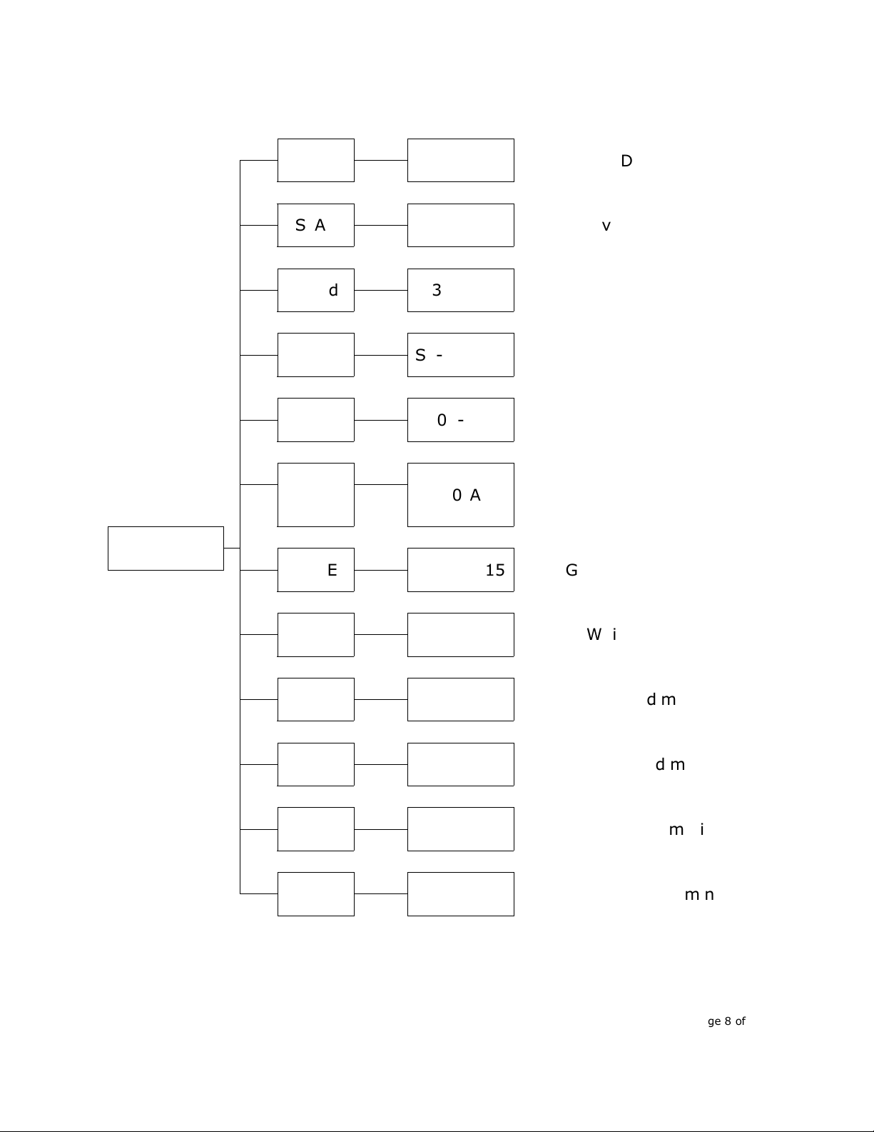
Details of program built inside
(
((
(
Pr- -
)
))
)
•Press MENU, go back to the initial setting
•Press UP / DOWN until Pr--
•Press ENTER to choose, the display will glinting at this moment
•Press UP / DOWN to change the address code to select pr00
•
Press ENTER to select and store the current menu options DMX mode will be
•
stored
automatically and the screen will stop glinting
•Remark: Pr14--- Pr30 Can change the content Of SP
,
correct the speed of jumping
change , SP00 is the fastest
,
SP15 is the slowest
•Pr00-Pr13
:
R,G,B W single color or multi-colors lighting
•Pr14-Pr28
:
correspond with the Pr00-Pr13 add the strobe function
•Pr29
:
4 colors jumping
•Pr30
:
there are kinds of colors jumping
Page 10 of 17

Operating Control Instruction
Master/Slave
Master
:
The master should set as built-in program and shows” P - X – X” send out
synchronization signals
To avoid the host signal and DMX512 signals interfere
with each other, should cut off the DMX512 signals The signal lines are longer
than 60 meters should increase a signal amplifier
Slave
:
It must be in the SLAV mode and the address code should be A001 to assure
receive the master’s signals correctly Only one light can be set as a Master and
others are slaves
XLR cable connecting
XRL cable:
::
:
The stand connection way of the XRL is: one end connects to the male plug, and
the other connects to the female
Noted
:
In order to avoid failures and interference signal transmission
,
we connect
a resistance120Ω (1/4) at the end of the DMX connecting as below:
Page 11 of 17

The Conversion between 3pin and 5 pin XLR
If the output cable of DMX512 controller is the 5PIN, please use 1pc 5PIN to
3PIN cable
Page 12 of 17

Connecting picture
Cable connecting picture:
Page 13 of 17

Problem Anal ze
Problem Checking way
Can not turn on the
light
Check the power source plug is in normal or not
Check the switch of the lights is off or on
Check it the fuse if in normal
DMX can not control
it
Check the DMX cable is connect to the lights or not
Check the DMX512 controller work in normal or not
Check the DMX cable is normal or not
Check if the lights is in DMX mode(
A001)
Display not bright
When connect to the electricity,
did the led flash one time?
If so,
the power source is normal; If not,
please check if the
switch and the transformer has power out
Check if the power input of the IC board is normal
Check if the cable connect to the display loose
Change the main board to see if it is normal
Change the display
LED not light
When connect to the electricity,
did the led flash one time?
If so,
the power source is normal; If not,
please check if the
switch and the transformer has power out
Check if the power input of the IC board is normal
Check if the cable connect to the display loose
Change the main board to see if it is normal
Change the display
LED is connect by leds in series first, then connect parallel,
so please check if the leds is loose

Some of the LED not
light
Use the multimeter to check if the led is bright or not, of
not, please change the led
check whether current limiting resistor is normal or not
Check constant current IC is normal or not (compared with
the normal IC)
Single color leds
always bright/not
bright
Check the switch of this color is normal or not
Change the IC control board
Noted: only professional persons can do as above
!
Page 15 of 17

Technical Specification
•Input voltage: AC 100V-264V/47-63HZ
•Output voltage:DC24V
•Consume:120W
•Lamp Type:4-in-1 LED
•Lamp Spec: High Power 8W
(
18PCS
)
•Constant current driver:500MA
•PWM Dimmer
:
>400HZ(16666 grades)
•Refresh rate:>400HZ
•Life span: 50000~100000hours
•Control Signal
:
DMX512, sound activated, auto run
•Control mode
:
stand alone/ sound activated
•Mode
:
CH3
、
CH 4
、
CH 5
、
CH 8
、
CH 9
•Color effect
:
RGBW mixing
•Function Effect: dimmer, strobe, eotic, gradual change, sound activated
•Beam Angle: 25°
•Cooling mode: Natural Convection
•Anti-electricity intension
:
1 5KV
•Insulation Resistance:
>2
MΩ
•Size:284*193*254mm
•Net Weight: 5KG
Page 16 of 17

Copyright 2012 KANDOLITE All rights
reserved Due to continuous improvements
and innovations, specifications may change
without notice
Table of contents
Other Kandolite Dj Equipment manuals