Kanematsu F-25V User manual

F-25V/F-25U/F-50V/F-45U
Operating Manual

INTRODUCTION
This Manual describes the operation for the Kanematsu Land mobile radio
This Land Mobile is full-featured FMtransceiver designed for flexible mobile and base station
business communications in the VHF or UHF Land mobile bands.
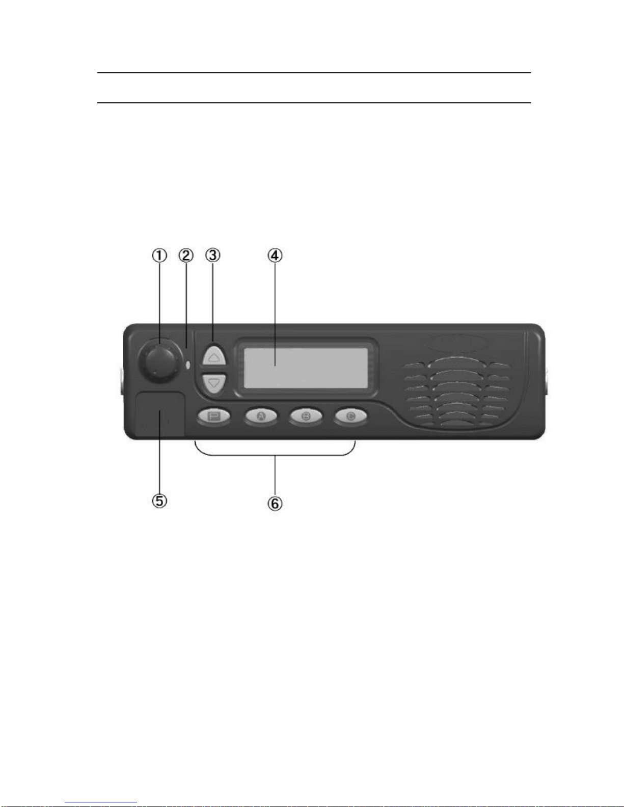
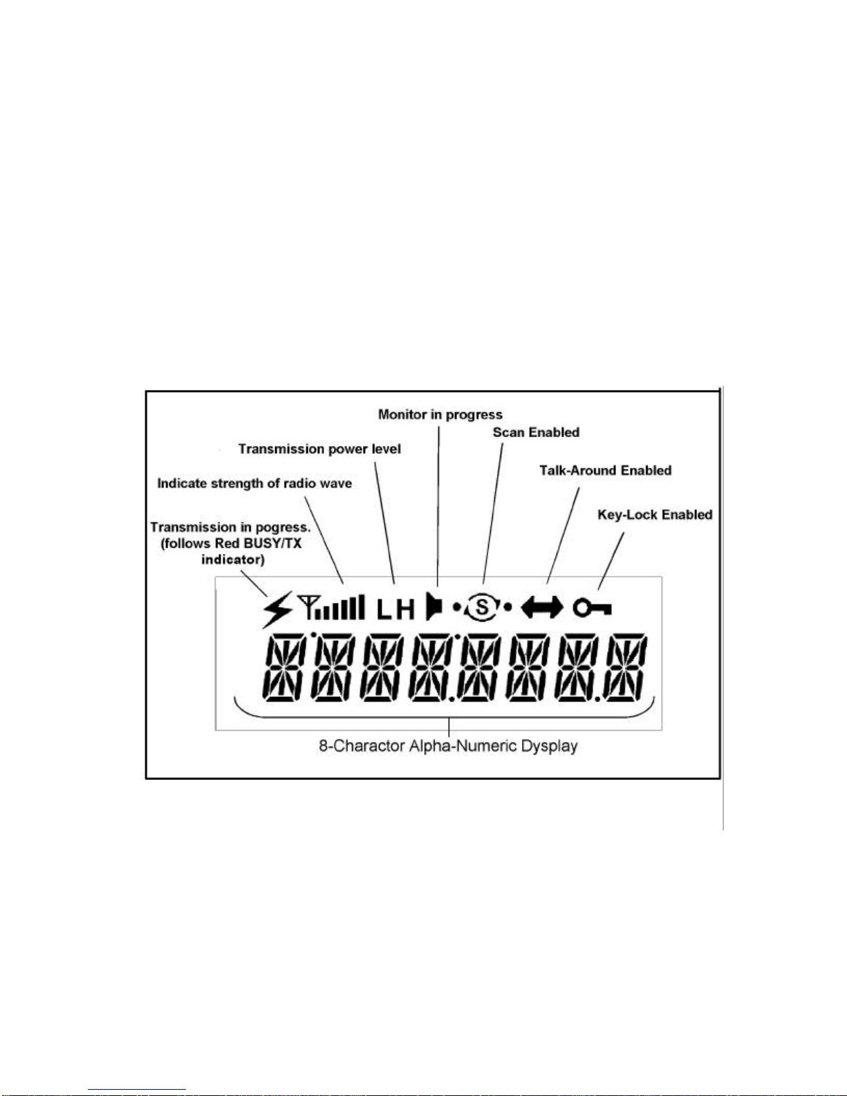
This Land mobile radio can be programmed with 128channels. This Land mobile include a 16
segment, 8character, numeric display for channel display.
Important channel frequency data is stored in EEPROM and flash memory on the CPU,
and easily programmable by dealers using personal computer and PC EDITER software.
FCC Requirements
Your radio must be properly licensed Federal Communications Commission prior to use. Your
Wireless dealer can assist you in meeting these requirements. Your dealer will program each
radio with your authorized frequencies, signaling codes, etc., and will be there to meet your
communications needs as your system expands.
SAFETY WANING INFORMATION
READ THIS IMPORTANT INFORMATION ON SAFE AND EFFICIENT OPERATION
BEFORE USING YOUR LAND MOBILE RADIO
・ Only qualified technicians are allowed to repair this product.
・ Do not operate the radio without a proper antenna attached. As this may damage the
radio and may also cause to exceed FCC RF exposure limits.
・ Typical electronic systems that may malfunction due to the lack of protection from radio
frequency energy present when transmitting. If the vehicle contains such equipment,
consult the dealer.
・ Just as it is dangerous to fuel a vehicle with motor running, similar hazard exist when
operation a mobile radio. Be sure to turn the radio off while fueling a vehicle.
・ Do not operate the radio without a proper antenna attached, as this may damage the
radio and may also cause you to exceed FCC RF exposure limits.
・ Do not transmit for more than 50% of total radio use time. Transmitting more than 50%
of the time can cause FCC RF exposure compliance requirements to be exceeded.
・ Always Keep at least 25cm (10inches) between the antenna and operator while
transmitting and 96cm between the antenna and the general population.
・ Always use authorized accessories.
・ Dynamite blasting caps may be caused to explode by operating a radio within 500 feet
of the blasting caps. Always obey the “Turn Off Two –Way radios”signs posted where
dynamite is being used.

・ Do not install the radio in the closed compartment that contains an LP gas container or
its fitting.
・ No changes or adjustments shall be made to the equipment except by an authorized or
certified electronic technician.
・ Using your radio to send personal messages is a violation of FCC rules.

Control and Connectors
FRONT PANEL
All Buttons on the Front Panel are Programmable Function (PF) Buttons, configured
according to your network requirements and programmed by your dealer. The instructions
below a typically configured radio
1VOL/PWR Knob
Turn this control clockwise to turn the radio on and increase the volume. Turn it
counterclockwise into the click-stop to the radio off.
2BUSY/TX Indicator
Indicate transceiver Transmit/Receive Status
Steady Red: Transmitting in progress
Steady Green: Busy Channel
3UP/DOWN Buttons (Programmable Function Buttons)
Pressing either button changes the current channel (and displayed name).

4LCD
The display includes and 8-character alphanumeric section showing channel names,
status and identity information, and error messages.
5Microphone Jack
Connect the microphone plug to this jack.
6[P]-[C] Buttons (Programmable Function Buttons)
These buttons can be set up for the special applications, such as High/Low power
selection, Monitor, Talk-Around, etc as determined by your network requirements and
programmed by dealer.
LCD Icons & Indicators

REAR PANEL
1Antenna Socket
The 50-ohm coaxial feed line to the antenna must be connected here, using a Type-M
(PL-259) plug.
213.8V DC Cable Pigtail with connector
The supplied DC power cable must be connected to this 2-contact. Use only the supplied
fused cable, extended if necessary, for power connection.
3 External Speaker Jack
An external loudspeaker may be connected to this 2-contact, 3.5mm mini-phone jack
Caution: Do not connect either wire of this line to ground, and be certain that the speaker has
adequate capability to handle the audio output (4W) from the radio.
4D-Sub 15-Pin Accessory Connector
External TX audio line input, PTT (Push To Talk), and external RX audio Line output
signals may be obtained from this connector for use with accessories such as data
transmission.

BASIC OPERATION
Important! –Before turning on the radio the first time, confirm that the power connections
have been made correctly and that a proper antenna is connected to the antenna jack.
Overview -Your authorized Dealer can program your radio for Conventional format.
RECEIVE
Switching Power ON
Turn power on by the VOL/PWR knob. The radio will beep, and become illuminated.
Press the UP/DOWN button to choose the desired operating channel. A channel name will
appear on the display.
Setting the volume
Turn the VOL/PWR knob clockwise to increase the volume, and counterclockwise to
decrease it.
Select a Channel
Press the assigned PF button to Up/down Channel.
The display can show channel numbers or channel labels. Technician along programs the
display mode and channel labels.
Transmitting
Press PF button, which is programmed to the Monitor feature to listen for channel activity
When receiving a call, transmit only after the incoming call ends. The radio cannot receive a
call and transmit simultaneously.
Press PTT switch.
If the channel is clear, the BUSY/TX indicator will grow red. The radio is now transmitting.
While holding in the PTT switch, speak across the face of the microphone in a clear and
normal voice. For best transmission, hold the microphone about 1-1/2 to 2 inches away from
your mouth. Release the PTT switch to receive.
If the Busy Channel Lockout feature has been programmed on a channel, the radio will not

transmit when a carrier is present. Instead, the radio will generate a continuous low-pitched
tone while PTT switch ispressed. Release the PTT switch and wait for thechannel to be clear
of activity.
If CTCSS or Digital Code Squelch (DCS) Lockout has been programmed on a channel, the
radio can transmit only when there is no carrier being received or when the carrier being
received includes the correct CTCSS tone or DCS code.
Time-Out Timer
If the selectedchannel has been programmed for Time-Out Timer, you must limit thelength of
each transmission, While transmitting, a beep will sound 10 seconds before time-out.
Another beep will sound just before the deadline; The TX indicator will disappear the
transmission will cease soon thereafter. To resume transmitting, you must release the PTT
switch and wait for the “penalty timer “to expire (if you press the PTT switch before this timer
expires, the timer restarts, and you will have to wait another “penalty”period)

ADVANCED OPERATION
Programmable Function Buttons
This land mobile radio includes six Programmable Function (PF) Buttons.The PF button
functions can be customized, via programming by your dealer, to meet your communication
requirements. Some features may require the purchase and installation of optional internal
accessories. The possible PF button programming features are illustrated below, and these
functions are explained on pages to follow.
For Future details, contact your dealer. For future reference, check the box next to the
function that has been assigned to each PF button on your particularradio, andkeep it handy.
MONITOR
Press the assigned PF button hears background noise (unmute the audio); the BUSY/TX
indicator will grow green.
SCAN 1-4
The Scanning feature is used to monitor multiple channel programmed into the transceiver.
While scanning, transceiver will check each channel for the presence of asignal, and will stop
on a channel if a signal is present.
Press the assigned PF button to active scanning.
The scanner will search the each channels, looking for active ones; it will pause each time if
finds a channel on which someone is speaking.
Press the assigned PF button again to disable scanning. Operation will revert to the before
scan start channel.
Note: Your dealer may have programmed your radio to stay on one of following channels if
you press the PTT switch during scanning pause:
‘Scan List Top channel’
‘Priority channel 1’
‘Priority channel 2’
SCAN Skip
Press the assigned PF button to delete the current pause channel for Scanning.

POWER
Press the assigned PF button to set the radio’s transmitter to the “Low Power”mode. Press
this button again to return to “High Power”operation when in difficult terrain.
Talk Around
Press the assigned PF button to activate the Talk Around feature when you are operating on
duplex channel system (separate receive and transmit frequencies, utilizing a “repeater”
station). The Talk Around feature allows you to bypass the repeater station and talk directly to
a station that is nearby. When TA is on, the radio transmit on the receive frequency of the
selected channel.
CALL 1-4
Press the assigned PF button to sent your radio’s identification code (ANI) to the dispatcher
(requires the Optional DTMF pager UNIT)
EMERGENCY
This land mobile radio includes an “Emergency”feature, which may be useful if you have
someone monitoring on the same frequency as your transceiver’s channel.
Press the assigned PF button to initiate an emergency call. For future detail contact your
dealer.
Display Invert
Press the assigned PF button to invert the LCD display to backward-facing readout.
Press the assigned PF button again to return the LCD display to frontward-facing readout.
Display Aliases
Press the assigned PF button to change the display information to channel aliases(Alphabet
8 character number).
Press the assigned PF button to change the display information to channel number.
SQL
Press the assigned PF button to squelch adjust mode. The current squelch level is displayed
on the LCD.The Squelch level ischanged by pressing thisbutton, current level is counted up.
Return to channel by pressing the other button again.
Tuning the tightens the squelch setting, allowing only stronger signals to open the squelch
and heard.

Public Address
Press the assigned PF button to turn the Public Address system on or off. When PA is on,
pressing the microphone PTT switch cause audio to rout the audio amplifier without enabling
the transmitter.
Key Lock
Press and hold in the assigned PF button for 2 second to lock the front panel buttons; this can
be enabled to prevent radio setting from being disturbed.
MEMO CH 1,2
Press the assigned PF button to recall the programmed channel directly.
DTMF system
(Requires the optional DTMF Unit)
This system allows selective calling, using DTMF tone sequences.
When your radio paged by a stations bearing a tone sequence, which matches yours, your
radio’s squelch will open and the alert ringer will sound.
This manual suits for next models
3
Table of contents
Popular Radio manuals by other brands

Noxon
Noxon iRadio 310 quick start guide

ZyXEL Communications
ZyXEL Communications ZyXEL ExpWave 240B user guide

Realistic
Realistic Pro-53 owner's manual

Exalt
Exalt ExtendAir series quick start guide

Blaupunkt
Blaupunkt PP20 owner's manual

Midland Radio Corporation
Midland Radio Corporation 70-101BD user manual