Kanga Products FMT MK4 User manual

FMT MK4 Instructions Rev 10 Page 1 30/9/2023
FMT MK4 Feature rich CW Trainer
This is new version of the FISTS Morse tutor
project, this time after many requests it is
offered as a cased kit. I addition a number of
new features have been added too.
Now the FMT will support BOTH Paddle and
Straight keys in practice mode and an
additional fixed low level SINEWAVE output
is provided. This output can be connected to
a PC for use in a number of ways, the first is
when its used with a software package such
as CWGet, FLdigi etc you can check your own
sending in practice mode, the FMT does NOT
have a Morse decoder built in but this way you can see how good (or Bad!) your sending really is.
Another useful use for this output is to use the practice oscillator over Zoom or other internet streaming
type services.
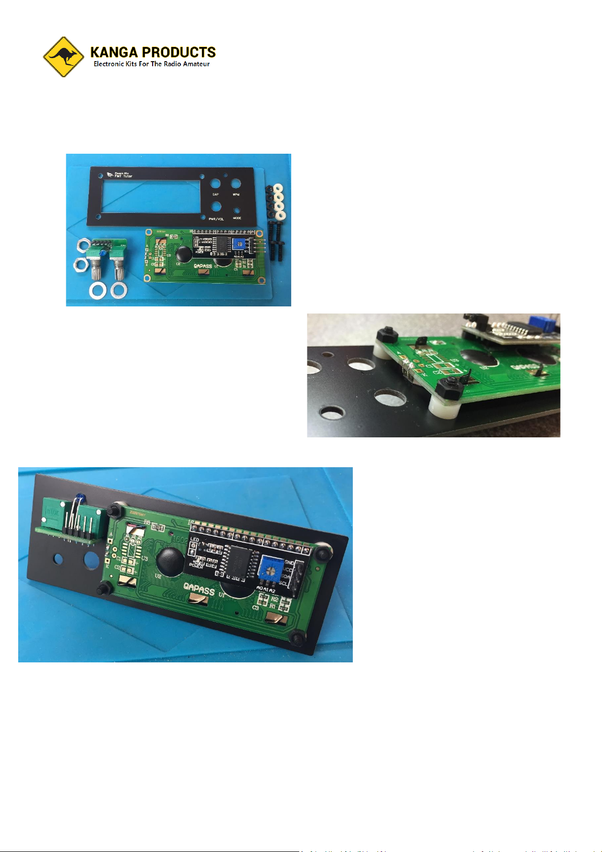
The kit is easy to build and due to coming with pre-punched front and back panels a better finished
product is assured (no more cutting out holes for the large LCD display)
Designed originally for the FISTS CW Club this tutor offers a wide range of features that you will find
hard to beat. The FMT Now has had a BIG addition to its feature list, it now has all the tutor features you
would expect but also as a 39 lesson Koch trainer built in too, I believe that this is the best way to learn
the code and is great for someone completely new to this mode.
Of course you also get all the original FMT Tutors features.
The Standard tutor modes are:
Random Letters, Random Numbers and Mixed Modes which is the standard from the old type of tutors,
but this tutor also much more;
Random Prosigns, Random Callsigns, Random common words and abbreviations, Contest mode (More
on that later) and even a practice oscillator (Straight key, Iambic paddle, and Cootie mode too) and a 10-
minute practice session timer.
The tutor is very simple to use, no pages of menus to navigate your way around, just one push button
that changes the mode and 3 knobs, one for character speed, one for the gap between characters and
finally a volume control.
Learning the code can be hard and you do need to stick to it, but don’t spend too long per session, it’s
not beneficial. I suggest keeping to a 10 min session once a day, every day. To help you know when a
session is up the tutor will illuminate a LED for 10 secs every 10 Minutes. This is a sign that you may
need to take a break.

FMT MK4 Instructions Rev 10 Page 2 30/9/2023
Now a note about the contest mode, ok what is contest mode? Well, the tutor will send a typical contest
type ‘Over’. It will send a random callsign followed by a three digit serial number, finally a short random
message ending such as ‘GD DX’, a 4 digit locator (Not necessarily the one for the callsign !) , RST Report,
or ‘QRZ’ etc.
That’s all well and good but to add to the realism as much as possible the pitch between overs and also
the speed will change randomly if you select the ‘ACM’ (Advanced Contest Mode) on the tutor’s board
(a two pin jumper enables it). You may want to start with the standard contest mode but you can
change to ACM at anytime. ( I activate it all the time on mine)
The tutor will generate code from about 12 to nearly 30 wpm, if this gets too tame for you then you can
push the tutor up to above 50WPM, another jumper on the main PCB selects this ‘Hyper’ mode.
In addition, the user can change the default tones pitch to their own liking. (See users guide)
Select practice mode and plug either a straight, Paddle, or Cootie key in and you have a practice
oscillator to play with too. (Paddle and Cootie key options are new in this MK4 version)
The FMT will now allow you to select Iambic A or B mode and also gives the option for left or right
handed paddle use
In Koch Mode the tutor will allow the user to select 1 of its 39 lessons and is the best way to learn
Morse, a great addition to the FMT.
The finial mode is the Prisoner of war Tap Code trainer /emulator, read the user guide for full details of
this historic code.
A New Feature!
The FMT has the option now of being used as a basic keyer for your radio (if you no longer need the
AUX audio output) if you have a paddle key connected, the speed and Iambic mode are selectable in
this mode.

FMT MK4 Instructions Rev 10 Page 3 30/9/2023
How to build the FMT?
Read ALL the following instructions BEFORE you start.
Check you have all the parts before you start.
FMT PCB
Mini Controls PCB
Mini Brightness Control PCB
Hammond RM2015M case
Front and Back Punched/Screen Printed Panels
4 x Stick on feet
DC Power Socket
3 x 3.5mm PCB Sockets
PCB 8 Ohm Speaker
9V Battery holder
3 x Battery holder fixing screws
4 x PCB fixing Screws
IC1 ATMEGA328 Processor Chip Keep on antistatic foam till needed (ESD protection!)
Socket 28 Pin IC Socket
2 x 10K potentiometer
1 x 10K potentiometer with integrated switch
1 x PCB Push Button
3 x Control Knobs
1 x 3mm Alarm Blue LED
1 x 4 Core connecting cable
1 x 5 Core connecting cable
1 x 2.54mm jumper
1 x 2.54mm 2 Pin Female Header
1 x 2.54mm 3 Pin Header
1 x 2.54mm 4 Pin Header (to be fitted to main PCB for display wiring)
1 x 2.54mm 5 pin straight Header ( fitted to main PCB for Control board)
1 x 2.54mm 5 pin 90 degree Header (fitted to small control PCB)
1 x Mounting Spacers/Hardware pack
1 x 2 line LCD Display
1 x 8 way switch
1 x 2K trimmer control
The build of the Morse Tutor is straight forward and shouldn’t present much in the way of problems.
This version now uses a number of SMD parts, ALL SMD parts are pre-installed.

FMT MK4 Instructions Rev 10 Page 4 30/9/2023
Building the FMT is an easy project, lets start with the 28pin IC socket, this socket has a little notch by
one end. Make sure you pace the socket to match the outline on the PCB.
Notch this end.
Next fit the 8 way switch, again place it to match the outline so the numbers on the switch and the
board match up.
Then fit the three jack sockets and the power socket.
Two near to the power socket and one further along the same
edge of the board.
Next fit the header pins. There is a 3,4, & 5 way set of
header pins. One for the display, one for the GAP/Speed
control board and one for the Key/AUX option. Make
sure these are fitted so they are at 90 degrees to the
board (Vertical)

FMT MK4 Instructions Rev 10 Page 5 30/9/2023
Now fit the battery holder. There are two types that may be
supplied with the kit, the first has two wires a red and black.
Cut these leads from the holder to about 20mm, strip the ends
of the wires by 3 mm and twist/ tin the ends, solder the wires
in place
Follow the layout silk screen shows where each wire needs to
go.
Then position the holder so the wires are under it and secure in
place from the BOTTOM of
the board with the three
small black self-tappers
provided.
The other battery holder option is a holder with two steel pins,
if you have this version place it on the board and attach it to the boards with the three screws provided
BEFORE you solder it in place, (screws to be fitted from the BOTTOM of the board), once secure then
solder and trim the leads.

FMT MK4 Instructions Rev 10 Page 6 30/9/2023
We only have a few parts left to fit now.
Now we can fit the power control and the small
mode push switch. IMPORTANT NOTE Follows
The combined volume
and power switch should
be fitted onto the main
PCB but before you do
you will need to remove
the Tab from the body of
the pot, it will snap off
easy, I use my cutters
and try and bend the
tab, it will snap off
without much effort.
Now fit the mode switch, this fits next to the volume control on the PCB. Make sure it is sitting nice and
flat onto the PCB.
.
Now we need to build up the small control PCB board.
Fix the 5 Pin Header to the board, you will have a new 90 degree bent
pin version. Make sure the bent pins are pointing towards the back of
the board NOT towards the position for the two controls or you will not
be able to plug a cable onto them.
Next fit the two 10K control potentiometers on the board, You MUST
break off the small tag on each of these controls as you did for the
volume control before. Finally, the blue LED. It may be worthwhile NOT
fitting that just yet as it needs to be the right height to fit into the hole
on the front plate, we will come to that in a moment
I have left the speaker till now as it’s very easy to get off cuts
of wire stuck inside its grill. So take it out of its bag and I
would suggest putting a little tape across its holes until you
finish the build.
Now to fit it.
If you look at the back of the speaker you will see a + and –
terminal. The ‘+’ pin must go into the hole marked SD+.

FMT MK4 Instructions Rev 10 Page 7 30/9/2023
Next move onto the front panel. These are the parts you will need for this stage
Fit the LCD module as shown below. Make sure that
you put the small white spacers between the panel
and the LCD display or the display will not sit
correctly. Before fitting the display module you will
see its 4 connection pins are bent over by 90
degrees. You will need to straighten these pins. Use
a pair of pliers and carefully bend the pins back to
the upright position. Make sure they are nice and
straight and all the same distance apart.
Now attach the small PCB to the front panel.
Bend the LED so that it can protrude through the
small hole between the GAP and WPM controls.
The LED as two leads, one longer than the other,
the long pin goes into the ROUND pads hole.
Once your happy with the position and height of
the LED solder it in place and trim the leads.
Note the pins on the display module in this picture. They are sticking out straight. Are yours??
Now fit the front panel loosely to the
main PCB, don’t tighten this up at this
time.
Find the bottom part of the case and
the back panel. Hold the back panel in
place next to the back of the PCB and
lower the lot into the case base. Now
use the 4 small self-tappers to secure
the PCB into the case.
Now is time to fit the Processor chip, it will be on an anti-static foam pad. Look carefully at the chip and
you will see a small dot near one pin. This is Pin 1, make sure this end of the chip is nearest to the multi-
way switch.

FMT MK4 Instructions Rev 10 Page 8 30/9/2023
Next we need to fit the cables between the board and the front panel. The first is for the display, take
the 4-way cable that came in the kit and plug it onto the main PCB in the position marked ‘DISPLAY’ its
the only 4 way header on the board.
The other end of the cable connects to the piggy back board on
the display, it will only work one way round. Look at the
pictures above to show you the correct way to fit the cables.
(note the picture shows the older PCB but the display cable is
fitted just the same)
Then you need to fit the control cables to the GAP/SPEED PCB
use a 5-core cable for this.
Fit the 9v Battery and turn on the tutor, the blue LED should
flash briefly and the display will light up. The text on the display
may be faint (or even not there at all!) or just a row of black squares. Adjust the small blue trimmer on
the back of the display board to set the display to your liking. By Now you should also be hearing the
sweet sound of Morse Code. Press and release the mode switch should allow you to move from one
mode to another, the volume, gap and speed controls should also be working.
You will still have a couple of parts left over, a small PCB marked ‘Brightness’ together with a trimer and
2-way female header. It is possible that this little board MAY be provided pre-built but most likely you
will have to assembly it yourself, This is a easy job, just be sure to fit the trimer and the 2 way socket
strip on opposite sides of the board
This little board replaces the jumper fitted on the back of the display module, it will allow you to adjust
the brightness of the screen.
If the display is not working check you have put the 4 way display cable the right way round. Same for
the controls. If all ok turn off and fit the top case and use the two long case screws to fix the two half’s
together. Use the 4 stick on feet on the bottom of the case

FMT MK4 Instructions Rev 10 Page 9 30/9/2023
You have completed the Tutor, good job!
You now need to look at the user guide for details on using the FMT and setting the options you want
for the 8-way switch.
I have given you some standard settings below for the switches that most people will be happy with,
feel free to change them. (Read the user guide first)
Default Switch Settings (Details of functions in instructions)
Switch Setting
1 Left/Right Paddles Standard (ON Default, OFF Reve Paddles)
2 Full Screen Hold (OFF Default)
3 Iambic A/B (ON Default= Iambic B / OFF=Iambic A)
4 Advance Contest Mode (ON Default)
5 Hyper Speed setting (OFF Default)
6 Volume Limiter for Headphones (ON Default)
7 & 8 Not Used in this firmware
Also set the small jumper on the 3-way header pins so that it’s on the bottom two pins.
Popular Fitness Equipment manuals by other brands

HeartSine
HeartSine samaritan SAM 350P user manual

ShoulderSphere
ShoulderSphere ShoulderSphere Instructions for use

Hoist Fitness
Hoist Fitness HR1 Super Trainer Assembly instructions

Beurer
Beurer EM 49 Instructions for use

Nautilus
Nautilus NP-R8009 Owner's manual and installation instructions

FLYBIRD
FLYBIRD JF01-SZJ user manual