Kango K 350 Setup guide
1
PAGE
Repair Instructions
K 350
Important! Before carrying out any repairs, the hammer should be checked for electrical safety and for mechanical
performance. For electrical safety the hammer should be placed on a non-conductive surface which is
either of a wooden construction (with the mains supply disconnected) which contains no metal parts or
a bench which is insulated by a rubber mat. The hammer should then be checked by high voltage flash
testing. On completion of dismantling procedure all electrical components should then be checked for
electrical safety. The hammer should ONLY be checked for hammer performance if the unit passes the
electrical safety test.
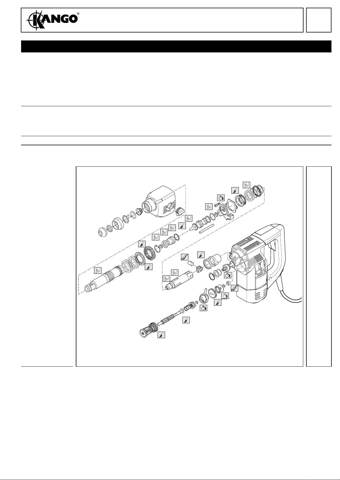
Disassembly
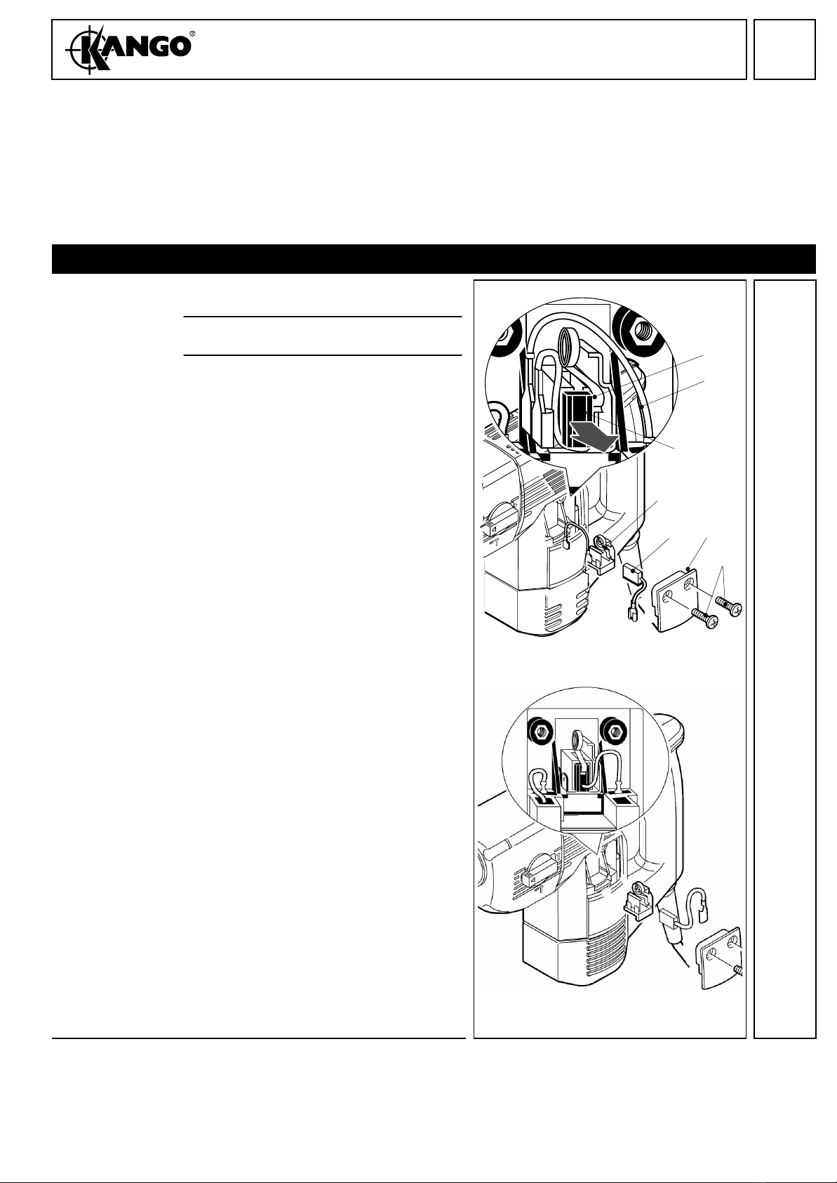
Removing the
carbon brushes 1Remove the attaching bolts (85) and the
protective cap (9).
2Disconnect the wire (B) and pull the brush
holder (15) from the housing.
3Movethespring(A)aside(seeillustration)
and remove the carbon brushes (88).
Disconnect the carbon brush cables.
☞From date of construction 03/99, the
carbon brush connection is located di-
rectly on the field. 88
B
A
15
88 9
85
➞ 03/99
03/99 ➞
1
2
PAGE
Repair Instructions
K 350
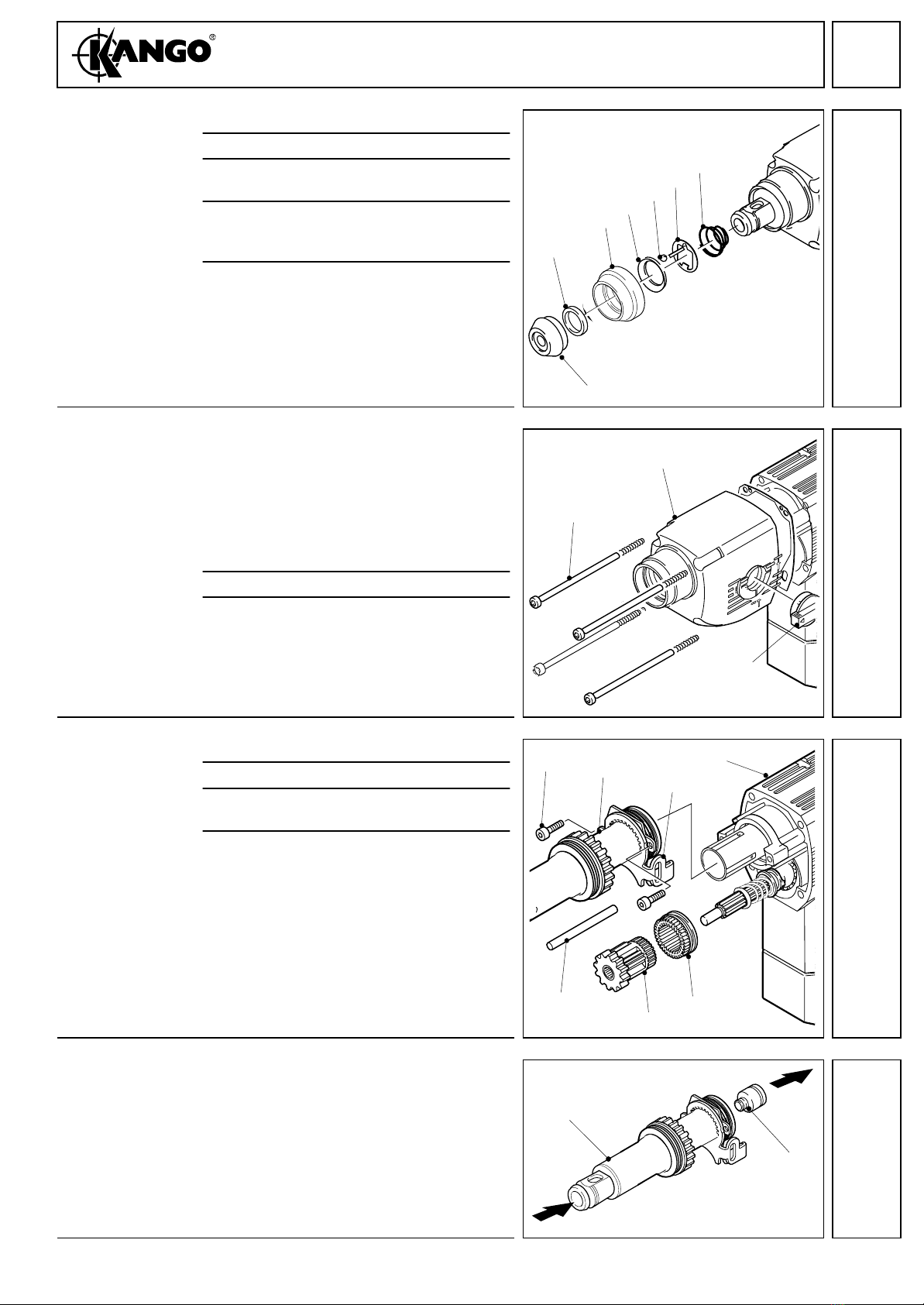
Dismantling the
SDS-Plus-Recep-
tion
1Remove the rubber cover (87).
2Remove the spacer (60).
3Remove the sliding sleeve (87) and the re-
taining ring (64).
4Depress the support plate (63) and press
out the ball (62) with the aid of a screw-
driver or remove it with a magnet.
5Remove the support plate (63) and the
pressure spring (61).
Removing the
gear housing 1Removing the switch lever (87):
Switch the lever to the hammer only posi-
tion and break it off with aid of pliers (the
lever is being destroyed).
Note: Should this not be possible mount
theswitch ina viceand breakit offby rock-
ing the machine. Remove any broken
parts from the machine.
2Remove the four housing bolts (85).
3Remove the gear housing.
Removing the
spindle 1Remove the two bolts (85).
2Remove the pin (44).
3Remove the offset gear (37) and the ring
gear (38).
4Remove the complete spindle sleeve (46)
from the cylinder.
Removing the
striker 1Position the spindle (46) vertically and
briefly hit the plunger using a suitable
drift - the striker (39) comes free.
60
87 64 62 63 61
87
2
25
85
87
3
43
85 46 27
44 37 38
4
46
39
5

3
PAGE
Repair Instructions
K 350
Dismantling the
spindle
(removing the
outer parts)
1Removing the rear thrust bearing assem-
bly: Lever off the spiral clip (53) with a
screwdriver. Remove the thrust bearing
assembly in the following component
parts:
– washer (58)
– thrust bearing (52)
– two compensating washers (65)
– profile ring with damper O-ring (51)
2Remove the retaining plate (45) and the
slider (43).
3Removing the spindle gear (49):
Press the spindle gear (49) using a suita-
ble sleeve against the cup springs (47) -
the spring ring (50) is released and can be
removed with pliers. Remove the spindle
gear (49).
4Remove the stop washer (48) and the cup
springs.
Dismantling the
spindle (remov-
ing the inner
locking ring)
To remove the locking ring, service tool
4.931 5990 84 is needed (see illustration 7).
1Turn the locking ring (53) with aid of serv-
ice tool, such that one end projets the
service boring by approx. 2 mm.
2Put a screwdriver through the service bor-
ing and place it under the locking ring (53).
3Move the screwdriver to and fro and at the
same time turn the locking ring with aid of
the service tool in direction of arrow. Turn
the locking ring until it is completely lev-
ered off.
4Press the locking ring from the spindle.
47 48 4950 43 45
53
50
47
49
58
5152
65
6
53
B
A
53
7

4
PAGE
Repair Instructions
K 350
Dismantling
the spindle
(inner parts)
1Press the following parts from the
spindle (46):
– backing flange (56)
– sleeve (54)
– snap die (57)
– sleeve (59)
2Remove the O-rings (87).
Removing the
back gear shaft
and the cylinder
1Pullout thebearinghousing(70)orloosen
the bearing housing by hitting the gear
housing lightly with a plastic hammer.
2Remove the tumble drive (35) and the cyl-
inder (40).
3Press out the bolt (42) by hand and re-
move the two disks (41) (older machines:
guide ring (see box).
4Remove the needle bearing (87) with aid
of an interior extractor. In case of older
machines, remove the 13 rollers (90) from
the back gear shaft.
Dismantling the
back gear shaft 1Remove the “O” ring (87).
2Remove the disk and the thrust
bearing (30).
3Press off the reduction gear (36).
4Remove the remaining parts from the re-
duction gear shaft (29):
– tumble drive (35)
– disk (34)
– coupling sleeve (33)
– spring (32)
– disk (31)
54
59
46 87 57
56
87
09/97
8
08/9608/96
09/97
70
42
41
40
35
87(90)
9
29
31 32 3334 35 36 87
30
10

5
PAGE
Repair Instructions
K 350
Removing the
angle drive 1Remove the locking washer (67).
2Remove the shaft (82) together with the
discs (72 & 73) and the ring (71). (If nec-
essaryby hitting the gear box lightly with a
plastic hammer).
Note: Depending on the tolerance of the
bearing,thetoolcanbeequippedwiththetwo
or three discs (72 &73). Note the numbers of
the discs and use the same number when re-
assembling.
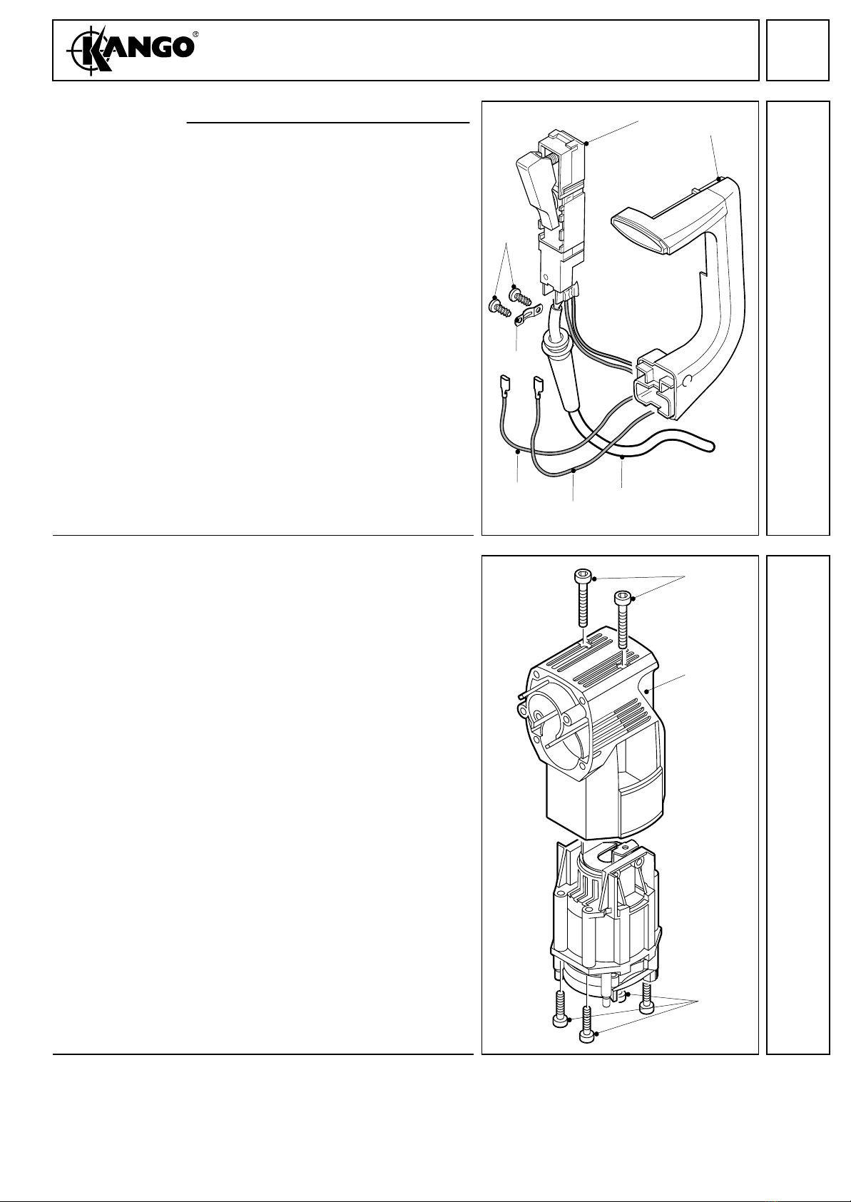
Removing the
motor cover 1Remove the four bolts (85) and remove
the protective cap (8).
Dismantling
the handle 1Remove the pin (4).
2Disconnect the field supply cables (18,19)
from the contacts and pull them from the
field housing.
3Removetheattachingscrews(85)andthe
handle cover (86).
4Remove the silicone buffer (12).
5Remove the locking ring (6) and the wash-
er (5).
6Remove the AVS-rubber (87).
7Remove the handle (86).
8Unscrew and remove the handle bolt (68).
72
67
82 71
66
73
11
8
85
12
85
86 87 56
68
41
8
27 12
86
18,19
13
6
PAGE
Repair Instructions
K 350
Removing the
electrical parts 1Unscrew the cable collar (17).
2Remove following parts:
– switch (22/23)
– capacitor (24)
– cable (1)
– wire (18/19)
Removing
the motor 1Remove the bolts (85) and pull out the
motor (if necessary, hit the motor hous-
ing (27) lightly with a plastic hammer).
22/23
85
86
1
17
18
19
14
85
27
85
15
7
PAGE
Repair Instructions
K 350
Removing and
dismantling the
armature
1Remove the seal ring (21).
2Lever off the bearing cover (20) and re-
move the silicone buffers (12).
3Pull out the entire armature (74).
4Press off the gear wheel (82).
5Remove the spacer (81), sleeve (80) and
the bearing (77).
Removing
the field 1Remove the air deflector ring (11) and the
silicone buffers (12).
2Pull the field coil (10) from the casing (7)
and remove the centering ledges (16).
20 12
82
81
80
77
74
21
16
16
7
12
11
10
17
8
PAGE
Repair Instructions
K 350
Maintenance
General For best performance hammers should be serviced at regular intervals, any indication that the hammer
is not performing as specified should be investigated to prevent any adverse damage occurring.
ALL SEALS, GASKETS, GREASE OR OTHER PARTS DEEMED NECESSARY FOR SERVICING
ARE IN THE SERVICE KIT.
ALL NEEDLE ROLLER BEARINGS SHOULD BE PRESSED WITH THE ROUNDED EDGE ENTER-
ING THE BORE FIRST, AND THE PRESS TOOL PRESSING AGAINST THE FLAT SURFACE OF
THE BEARING.
Cleaning All mechanical parts with the exception of any sealed bearings should be cleaned in a suitable cleaning
fluid. Electrical parts should be cleaned by the use of compressed air.
PRECAUTIONS MUST BE TAKEN FOR PERSONAL SAFETY THE USE OF EYE PROTECTION
AND GLOVES IS RECOMMENDED.
Check for wear Check the disassembled parts for wear (visual inspection) and replace worn parts.
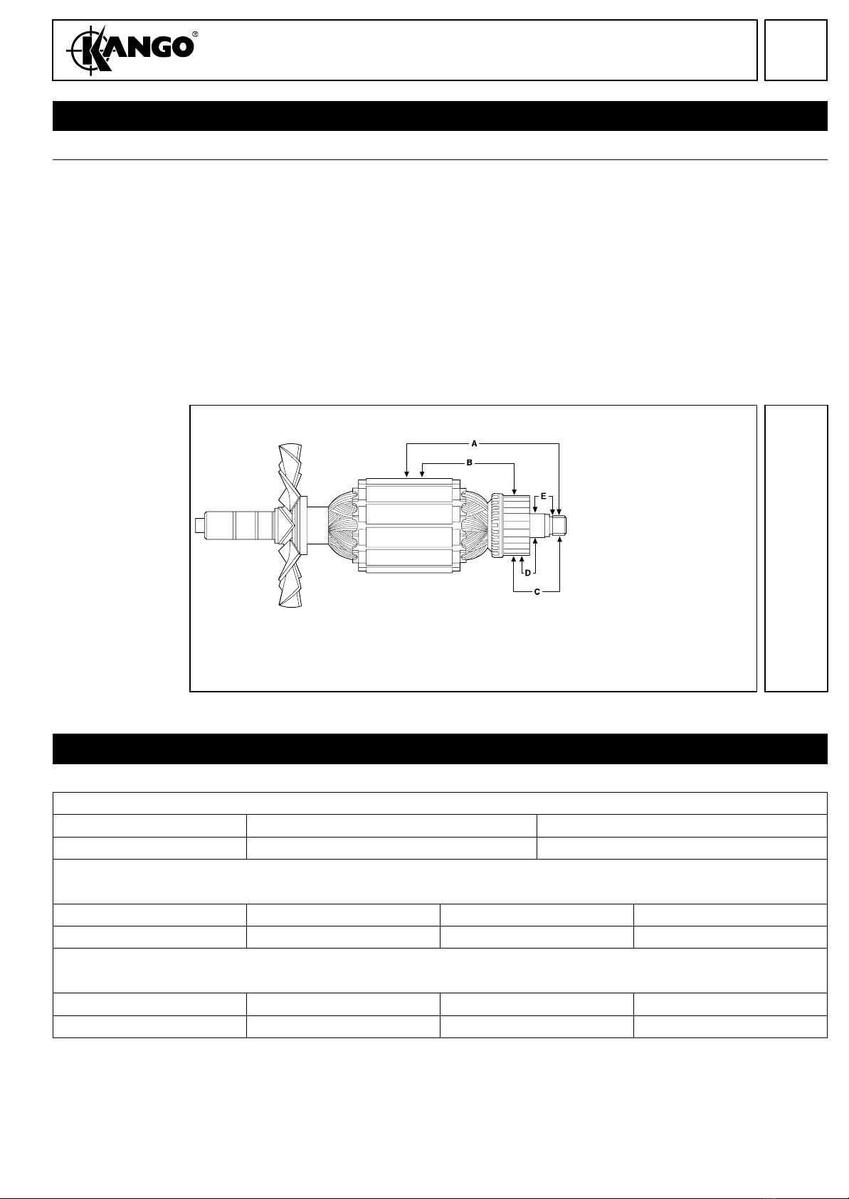
Lubrication At service and repair intervals the lubrication should be carried out as shown in the diagram below.
All parts in the service kit should be fitted. The total amount of grease for the 350 is 30 grms (1 tube)
(9170 3043 23, blue). Lubrication of the hammer is as shown on the grease chart.
ALL SCREWS SHOULD BE REFITTED WITH LOCKTITE 222 OR SIMILAR.
D
A
B
E
E
E
E
E
G
H
I
K
LM
N
O
P
Q
F
F
C
S
T
U
1g
1g
1g
1g
1g
2g
8g
4g
4g
1g
1g
1g
1g
4g
0.5g
0.5g
0.5g
0.5g
5g
2g
2g
9
PAGE
Repair Instructions
K 350
ELECTRICAL TESTING
Electrical tests Before assembly all electrical parts MUST be checked for safety, and that they conform to specification.
Testing the
Armature
(Flash Testing)
Supplementary Insulation
Apply 1250 volts rising to 2500 volts A.C. between laminations and spindle (A). See dia-
gram.
Basic Insulation
Apply 750 volts rising to 1500 volts A.C. between commutator segments and lamina-
tions (B). See diagram.
A Armature shaft to lamination pack 2500 volts
B Lamination pack to commutator 1500 volts
C Armature shaft to commutator 4000 volts
D Commutator to commutator bush 1500 volts
E Commutator bush to shaft 2500 volts
ELECTRICAL PERFORMANCE TEST READINGS
ARMATURES
MODEL 110V/120V 220V/230V/240V
350 0.927Ω3.297Ω
FIELD COILS
110V/120V 220V/230V 240V
350 0.121Ω0.429Ω0.499Ω
PERFORMANCE
110V/120V 220V/230V 240V
350 17 amps 10 amps 9 amps
Note: On all test readings + or - 5% of figures shown is acceptable.
Table of contents
Other Kango Power Hammer manuals


Popular Power Hammer manuals by other brands


Pattfield Ergo Tools
Pattfield Ergo Tools PA-1700SH Translation of the original instructions

Coleman
Coleman Powermate 024-0075SP instruction manual

Makita
Makita HR3210C Parts Breakdown

WilTec
WilTec JH95A Operation manual

Master
Master MH 10-SE Translation of the original instructions

Stark
Stark RH 1300 DB user manual