Kannad INTEGRA ARINC e-NAV User manual

Orolia S.A.S.
Z.I. des Cinq Chemins CS10028
56520 GUIDEL - FRANCE
Telephone: +33 (0)2 97 02 49 49 Fax: +33 (0)2 97 65 00 20
Web : http://www.mcmurdogroup.com
E-mail : info@mcmurdogroup.com
REF.: DOC13033
INDEX: B
DATE: SEP 14/2016
INTEGRA ARINC e-NAV
DESCRIPTION, INSTALLATION,
OPERATION MANUAL
P/N S1850581-01

© Orolia S.A.S.
Users are kindly requested to notify Orolia S.A.S.
of any discrepancy, omission or error found in
this manual.
Please report to our customer support:
E-mail: [email protected]
Tel.: +33 (0)2 97 02 49 00

INTEGRA ARINC e-NAV
DESCRIPTION, INSTALLATION,
OPERATION MANUAL
PAGE: TOC 1 of 2
REF.: DOC13033
INDEX: B
DATE: SEP 14/2016
© Orolia S.A.S.
CONTENTS
1. SYSTEM PRESENTATION......................................................................... 1
1.1. General .....................................................................................................................1
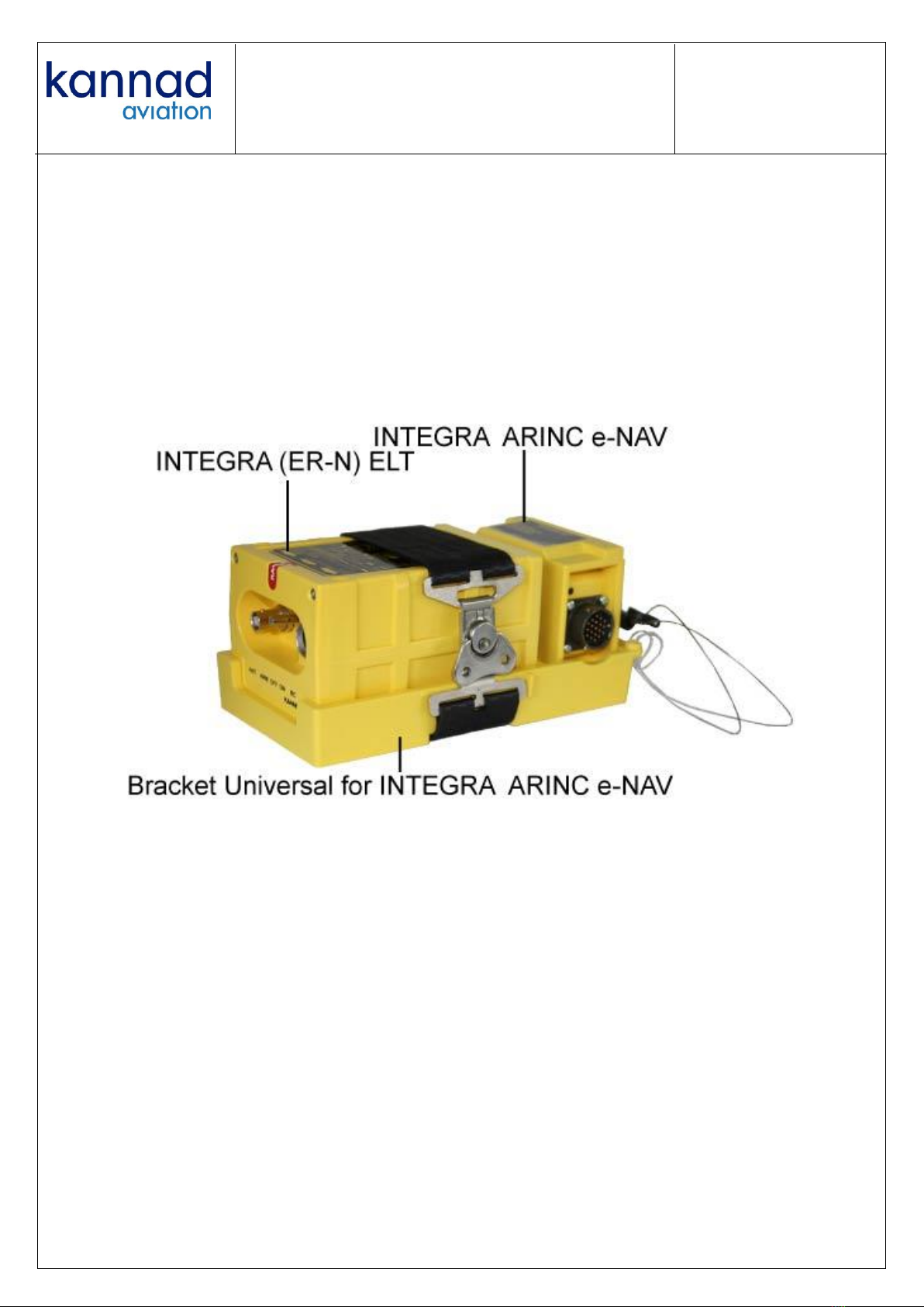
1.2. INTEGRA ARINC e-NAV Presentation....................................................................1
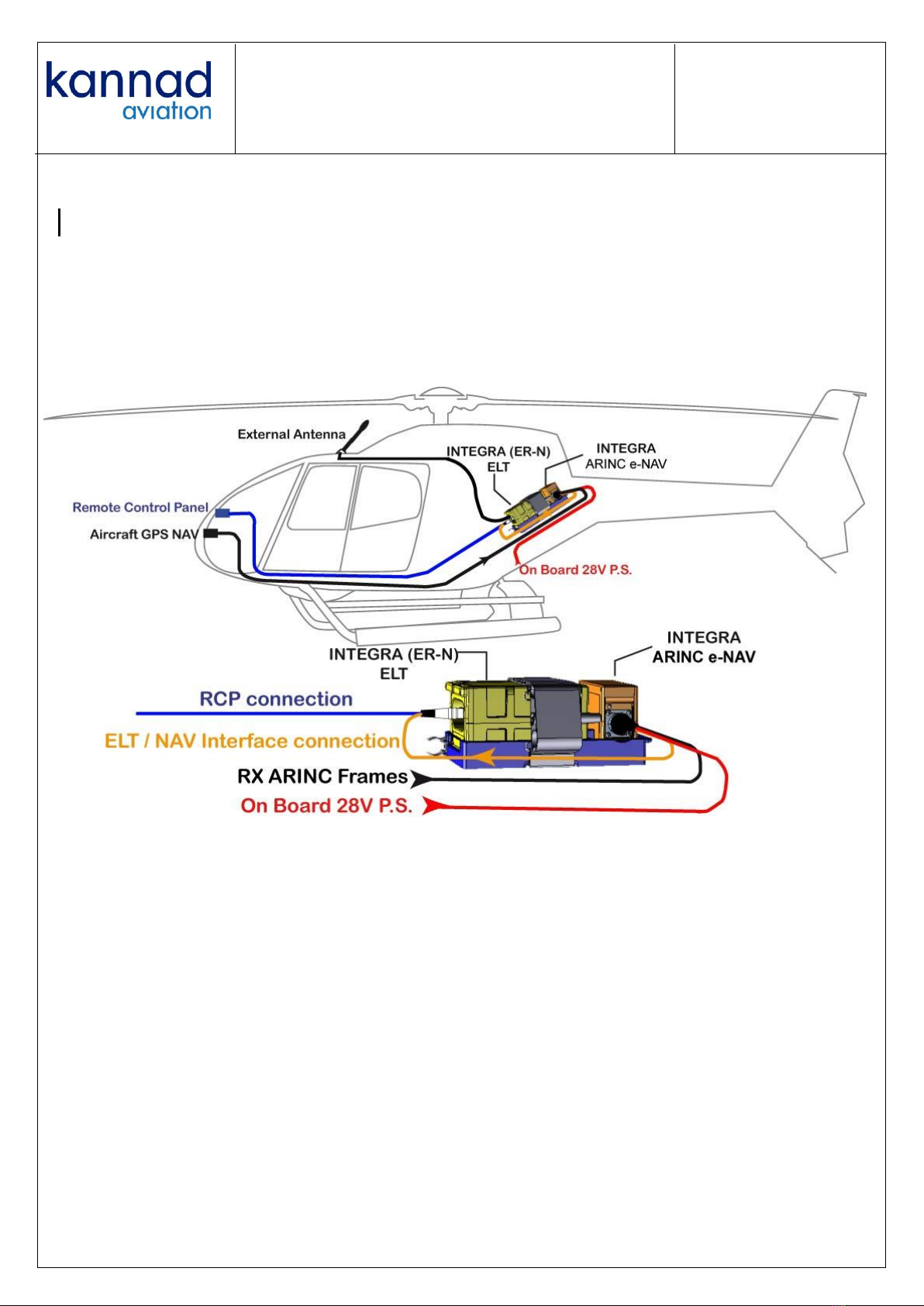
1.3. Concept ....................................................................................................................3
2. INTEGRA ARINC e-NAV INSTALLATION ................................................. 4
3. INTEGRA ARINC e-NAV CONNECTION ................................................... 5
3.1. Connectors and Cables ..........................................................................................5
3.2. Connection to On Board 28V DC Power Supply ...................................................5
3.3. Connection to On Board GPS Equipment .............................................................5
3.4. Connection to INTEGRA (ER-N) ELT .....................................................................5
4. FIRST POWER UP PROCEDURE.............................................................. 6
4.1. Check of the ELT .....................................................................................................6
4.2. Check of on board GPS equipment .......................................................................6
4.3. Position Data Verification .......................................................................................6
4.3.1. Tester Connection..............................................................................................6
4.3.2. Test preparation..................................................................................................7
4.3.3. Validation Procedure...........................................................................................7
4.3.3.1. SELF TEST .....................................................................................................7
4.3.3.2. Data Position Check ........................................................................................8
5. OPERATION ............................................................................................... 9
6. TECHNICAL CHARACTERISTICS .......................................................... 10
6.1. Weight and Dimensions........................................................................................10
6.2. ARINC Frames Specifications ..............................................................................10
6.3. Environmental Characteristics.............................................................................11
6.4. Temperatures Specifications................................................................................12
6.5. Electrical Characteristics......................................................................................12
6.6. Compatibility List ..................................................................................................12
6.6.1. ELT ...................................................................................................................12
6.6.2. Mounting Brackets ............................................................................................12
6.6.3. GPS ..................................................................................................................12
7. CONNECTING DIAGRAM ........................................................................ 13
8. SERVICING............................................................................................... 14

INTEGRA ARINC e-NAV
DESCRIPTION, INSTALLATION,
OPERATION MANUAL
PAGE: TOC 2 of 2
REF.: DOC13033
INDEX: B
DATE: SEP 14/2016
© Orolia S.A.S.
LIST OF FIGURES
Figure 1: INTEGRA ARINC e-NAV Overview ................................................. 1
Figure 2: Example of INTEGRA ARINC e-NAV installed on Mounting
Bracket ............................................................................................................. 2
Figure 3: INTEGRA ARINC e-NAV Concept ................................................... 3
Figure 4: INTEGRA ARINC e-NAV Installation .............................................. 4
Figure 5: 19 Pin female plug, View from Back Face of Inserts .................... 5
Figure 6: Beacon Tester Connection with ELT ............................................. 6
Figure 7: Connecting Diagram ..................................................................... 13

INTEGRA ARINC e-NAV
DESCRIPTION, INSTALLATION,
OPERATION MANUAL
PAGE: 1 of 14
REF.: DOC13033
INDEX: B
DATE: SEP 14/2016
© Orolia S.A.S.
1. SYSTEM PRESENTATION
1.1. General
INTEGRA ARINC e-NAV is an External Navigation Device (END) used for
INTEGRA (ER-N) ELTs family and navigation equipment through
ARINC 429/743.
INTEGRA ARINC e-NAV External Navigation Device is used to store GPS
data coming from an on-board GPS ARINC429/ARINC743 output.
The position data is transmitted in the 406 MHz distress message as soon
as the ELT is activated.
This manual contains information to install and operate the INTEGRA
ARINC e-NAV, Part Number S1850581-01.
1.2. INTEGRA ARINC e-NAV Presentation
The INTEGRA ARINC e-NAV is composed of:
1. A housing to protect the electronic PCB.
2. An identification of the Firmware version on the cover of the housing.
3. A LED to indicate the INTEGRA ARINC e-NAV status.
4. A 19 Pin male socket to connect the INTEGRA ARINC e-NAV to the
ELT, A/C +28V DC and on board GPS.
5. Two fixing supports to attach the housing to a mounting bracket.
6. An identification label on the top of the housing.
Figure 1: INTEGRA ARINC e-NAV Overview

INTEGRA ARINC e-NAV
DESCRIPTION, INSTALLATION,
OPERATION MANUAL
PAGE: 2 of 14
REF.: DOC13033
INDEX: B
DATE: SEP 14/2016
© Orolia S.A.S.
The INTEGRA ARINC e-NAV is to be mounted on a specific INTEGRA ELT
mounting bracket:
Bracket Universal for INTEGRA ARINC e-NAV for ELT (AP), P/N
S1850551 –01 when connect to an AP INTEGRA (ER-N) or AP-H
INTEGRA (ER-N) ELT, or
Bracket Universal for INTEGRA ARINC e-NAV for ELT (AF), P/N
S1850551 –02 when connected to an AF INTEGRA (ER-N) or AF-
H INTEGRA (ER-N) ELT.
Figure 2: Example of INTEGRA ARINC e-NAV installed on Mounting Bracket

INTEGRA ARINC e-NAV
DESCRIPTION, INSTALLATION,
OPERATION MANUAL
PAGE: 3 of 14
REF.: DOC13033
INDEX: B
DATE: SEP 14/2016
© Orolia S.A.S.
1.3. Concept
The 19 Pin male socket has to be connected to 3 separate cables:
On Board 28 VDC power supply,
ARINC frames of the On Board GPS equipment.
DIN-12 plug of the ELT.
In addition, the ELT has to be connected to the Remote Control Panel and
to the external antenna.
Figure 3: INTEGRA ARINC e-NAV Concept

INTEGRA ARINC e-NAV
DESCRIPTION, INSTALLATION,
OPERATION MANUAL
PAGE: 4 of 14
REF.: DOC13033
INDEX: B
DATE: SEP 14/2016
© Orolia S.A.S.
2. INTEGRA ARINC e-NAV INSTALLATION
1. On the Bracket Universal, place INTEGRA ARINC e-NAV housing
onto its supports either with its connector on the left side or on the
right side.
2. Fix the INTEGRA ARINC e-NAV onto the mounting bracket with the 2
captive screws and tighten to a torque of 1.4 Newton per meter using
a torque driver with a 2.5 mm Allen bit.
3. Place the INTEGRA (ER-N) ELTs onto the Bracket.
4. Secure the INTEGRA (ER-N) ELTs into its bracket [refer to relevant
INTEGRA (ER-N) ELT manual].
Figure 4: INTEGRA ARINC e-NAV Installation

INTEGRA ARINC e-NAV
DESCRIPTION, INSTALLATION,
OPERATION MANUAL
PAGE: 5 of 14
REF.: DOC13033
INDEX: B
DATE: SEP 14/2016
© Orolia S.A.S.
3. INTEGRA ARINC e-NAV CONNECTION
3.1. Connectors and Cables
3 separate shielded cables have to be wired to the plug connected to the 19
Pin male socket.
A 2-Wire cable to connect INTEGRA ARINC e-NAV to the On Board 28 V
DC power supply.
A 2-Wire cable to connect INTEGRA ARINC e-NAV to the On Board GPS
equipment
A 6-Wire cable to connect INTEGRA ARINC e-NAV to the ELT
Wires of AWG24 gauge should be preferred.
A 19 Pin female plug reference SOURIAU 851 06 R 14 19 S 50 shall be used
to connect the INTEGRA ARINC e-NAV (this plug is not provided)
Figure 5: 19 Pin female plug, View from Back Face of Inserts
3.2. Connection to On Board 28V DC Power Supply
Refer to Section 7, Connecting Diagram
3.3. Connection to On Board GPS Equipment
Refer to Section 7, Connecting Diagram
3.4. Connection to INTEGRA (ER-N) ELT
Fabricate a 6-wire cable long enough to reach the INTEGRA (ER-N) ELT.
On the ELT side, connect a DIN-12 connector, P/N S1820514-03 (Not
supplied).
IMPORTANT: It is not possible to use a programming dongle in this
cable.
Refer to Section 7, Connecting Diagram

INTEGRA ARINC e-NAV
DESCRIPTION, INSTALLATION,
OPERATION MANUAL
PAGE: 6 of 14
REF.: DOC13033
INDEX: B
DATE: SEP 14/2016
© Orolia S.A.S.
4. FIRST POWER UP PROCEDURE
This procedure can only be performed by the installer, as it requires specific
equipment such as a WS TECHNOLOGIES BT100 or any equivalent COSPAS-
SARSAT beacon decoder (AEROFLEX IFR 4000 opt1 for example) capable of
being connected to the BNC connector of the ELT in order to decode a
COSPAS-SARSAT digital message at 406.037 MHz.
4.1. Check of the ELT
Make sure that the ELT is programmed with a location protocol.
4.2. Check of on board GPS equipment
1. Check that the RX ARINC link of the aircraft GPS equipment is
activated (refer to the GPS equipment relevant manual).
2. Switch the GPS equipment to ON.
3. Wait for the acquisition of a GPS valid position on the GPS equipment.
4.3. Position Data Verification
CAUTION: Position data verification can only be checked if the ELT is
activated. Never perform position data verification by checking the position
data with the external antenna connected; in this case the 406 MHz would
be received by the Cospas-Sarsat Satellites and interpreted as a real
distress message. To avoid that, connect your beacon decoder to the
external antenna output socket.
4.3.1. Tester Connection
1. Disconnect the antenna cable from the ELT antenna socket
2. Connect a Cospas-Sarsat tester to the antenna socket of the ELT as
shown on figure 6 below:
Figure 6: Beacon Tester Connection with ELT

INTEGRA ARINC e-NAV
DESCRIPTION, INSTALLATION,
OPERATION MANUAL
PAGE: 7 of 14
REF.: DOC13033
INDEX: B
DATE: SEP 14/2016
© Orolia S.A.S.
4.3.2. Test preparation
CAUTION: On INTEGRA (ER-N) ELT, if both internal and external GPS
sources are available, the internal source is used.
To check the external GPS, make sure that the internal GPS is not
locked. Depending on the sky view, the internal GPS sometimes locks
even before the first burst at 50 seconds.
To make sure that the internal GPS will not lock, obstruct the top of the
ELT to make sure it doesn’t face the sky.
NOTE: The best way is to wrap the ELT in aluminum or copper foil.
4.3.3. Validation Procedure
NOTE: For ELT operation, refer to the relevant ELT Operation Manual.
1. After having performed all wiring tasks as indicated in Section
3.INTEGRA ARINC e-NAV CONNECTION, connect the 19 Pin female
plug to the 19 Pin male socket of INTEGRA ARINC e-NAV.
2. Connect the 2-Wire RX ARINC Frames cable to the On Board GPS
equipment..
3. Connect the 2-Wire +28 V DC cable to the +28 V DC On Board Power
Supply
4. Connect the DIN-12 connector of the ELT cable to the DIN-12 Plug of
the ELT
4.3.3.1. SELF TEST
1. Switch the ELT from OFF to ARM.
2. After 5 seconds the LED of INTEGRA ARINC e-NAV switches ON:
GREEN: +28V DC is correct and ARINC Frame is valid,
Red: +28V DC is not correct and/or ARINC Frame is not valid.
3. After 5 seconds, the LED switches OFF

INTEGRA ARINC e-NAV
DESCRIPTION, INSTALLATION,
OPERATION MANUAL
PAGE: 8 of 14
REF.: DOC13033
INDEX: B
DATE: SEP 14/2016
© Orolia S.A.S.
4.3.3.2. Data Position Check
1. Switch the ELT to ON.
2. 2 tests bursts are transmitted with default position (no position).
3. Wait 50 seconds until the first 406 MHz burst containing the GPS
position is transmitted by the ELT.
4. Read the position data on the Cospas-Sarsat tester.
5. Check that this position matches the GPS equipment’s position
IMPORTANT: depending on the protocol used, the position
transmitted by the ELT is rounded off to 4 seconds or 4 minutes (see
table below extracted from CS G005 standard):
Identification data
Location
Data
Protocols
Unique ELT Serial Number
4 minutes
User Location(1)
4 seconds
Standard Location
Aircraft Operator Designator & Serial
Number
4 minutes
User Location(1)
4 seconds
Standard Location
Aircraft 24-bit Address
4 minutes
User Location(1)
4 seconds
Standard Location
Aircraft Registration Marking
4 minutes
User Location
Serial Number Assigned by
Administration
4 seconds
National
Location(1)
NOTE (1): These protocols are not available by default in Kannad e-Prog
Software
6. Switch the ELT to OFF.
7. Disconnect the Cospas-Sarsat tester.
8. Connect the antenna cable to the antenna socket of the ELT.
9. If the aircraft is in operational condition, switch the ELT to ARM;
otherwise keep the ELT on OFF (see CAUTION below).
CAUTION: OFF mode must only be selected when the ELT is
removed from the aircraft or when the aircraft is parked for a long
period or for maintenance.

INTEGRA ARINC e-NAV
DESCRIPTION, INSTALLATION,
OPERATION MANUAL
PAGE: 9 of 14
REF.: DOC13033
INDEX: B
DATE: SEP 14/2016
© Orolia S.A.S.
5. OPERATION
NOTE: For ELT operation, refer to the relevant ELT Operation Manual.
All connections with the INTEGRA ARINC e-NAV are already done.
If the ELT switch is on OFF position, switch the ELT to ARM.
If the ELT switch is on ARM position, perform a self-Test by switching ELT
to OFF, then to ARM.
- After 5 seconds the LED of INTEGRA ARINC e-NAV switches ON:
GREEN: +28V DC is correct and ARINC Frame is valid,
Red: +28V DC is not correct and/or ARINC Frame is not valid.
- After 5 seconds, the LED switches OFF.
In the meantime, the ELT performs a Self-Test.
Check that the result of the ELT Self-Test is not faulty.
NOTE: Position will be transmitted only in the ELT is activated (manually by
switching to ON position or automatically if a crash occurs). The current position
will be transmitted about 50 seconds after ELT activation.

INTEGRA ARINC e-NAV
DESCRIPTION, INSTALLATION,
OPERATION MANUAL
PAGE: 10 of 14
REF.: DOC13033
INDEX: B
DATE: SEP 14/2016
© Orolia S.A.S.
6. TECHNICAL CHARACTERISTICS
6.1. Weight and Dimensions
Dimensions: 85 x 74 x 40 mm (3.346 x 2.913 x 1.574 in)
Weight: 176 g. (0.388 lbs) typical
6.2. ARINC Frames Specifications
The format of frames accepted by INTEGRA ARINC e-NAV are as follows:
ARINC Bits
32
31->30
29->9
8->1
Content
Parity
SSM
Latitude/longitude
Label
Latitude and longitude are encoded on 21 bits and use both Data field (bits
29-11) and SDI field (10 and 9 bits). Parity bit can be checked or not by
INTEGRA ARINC e-NAV.
ARINC RX1: ARINC positive input
ARINC RX2: ARINC negative input
Automatically manages both ARINC429/ARINC743 data rate: 12.5 kbits/s and
100 kbits/s.
NOTE: the data rate shall not be changed after power up.
Signed/Status Matrix (SSM) field shall
contain bits 11
Possible labels are the
following
Bit N°
Meaning
Label
Meaning
31
30
110
ARINC743 Latitude
0
0
Failure Warning
111
ARINC743 Longitude
0
1
No Computed Data
310
ARINC429 Latitude
1
0
Functional Test
311
ARINC429 Longitude
1
1
Normal Operation

INTEGRA ARINC e-NAV
DESCRIPTION, INSTALLATION,
OPERATION MANUAL
PAGE: 11 of 14
REF.: DOC13033
INDEX: B
DATE: SEP 14/2016
© Orolia S.A.S.
6.3. Environmental Characteristics
ENVIRONMENTAL CATEGORIES FORM FOR INTEGRA e-NAV ARINC
Qualification
Tests Title
ED62A references
(when applicable)
DO-160F
Section
Category
Temperature / Altitude
ED-62A (SPECIAL) Class1
4.0
As per ED-62A
Low Temperature
ED-62A (SPECIAL) -40°C
4.5.1
As per ED-62A
High Temperature
Activation
ED-62A (SPECIAL) +55°C
4.5.2 /3
As per ED-62A
In Flight Loss of Cooling
N/A
4.5.4
X
Altitude
ED-62A (SPECIAL) 50,000
ft
4.6.1
As per ED-62A
Decompression
ED-62A (SPECIAL)
4.6.2
As per ED-62A
Overpressure
§ 4.4.3 / ED-62A
4.6.3
As per ED-62A
Temperature variation
5
B
Humidity
6
C
Ops. shocks and crash
safety
ED-62A (SPECIAL)
7
As per ED-62A
Vibrations
Fixed Wings
8
R (C&C1)
Helicopters
U(G)(1)
Explosion proofness
N/A
9
X
Waterproofness
10
R
Fluid susceptibility
N/A
11
X
Sand and dust
N/A
12
X
Fungus
N/A
13
X
Salt spray
14
S
Magnetic effect
15
A
Power input
16
Z
Voltage spike conducted
susceptibility
17
A
Audio frequency
conducted susceptibility
18
Z
Induced signal
susceptibility
19
ZC
Radio frequency
susceptibility
20
Conducted: T
Radiated: L
Radio frequency
emission
21
H
Lightning transient
susceptibility
22
A2G33
Lightning direct effects
N/A
23
X
Icing
N/A
24
X
ESD
25
A
Fire, Flammability
ED-62A (SPECIAL FLAME)
26
As per ED-62A

INTEGRA ARINC e-NAV
DESCRIPTION, INSTALLATION,
OPERATION MANUAL
PAGE: 12 of 14
REF.: DOC13033
INDEX: B
DATE: SEP 14/2016
© Orolia S.A.S.
Environmental Categories
Fixed wings versions: RTCA DO-160G / EUROCAE ED14G chapters 4 to
26
- [ED62A]X[ED62A]C[ED62A][R(C&C1)U(G)]XRXXXSAZAZ[ZC][TL]H[A
2G33]XXA[ED62A]
Helicopters versions: RTCA DO-160G / EUROCAE ED14G chapters 4 to
26
- [ED62A]X[ED62A]C[ED62A][U(G)]
XRXXXSAZAZ[ZC][TL]H[A2G33]XXA[ED62A]
Storage temperature: -55 °C to +85 °C
6.4. Temperatures Specifications
Operating: -40 °C to +55 °C (Class 1)
Storage: -55 °C to +85 °C
6.5. Electrical Characteristics
Power supply: Aircraft +28 VDC
Consumption: 7 mA typical, 12.5 mA max@28 V (established mode).
300 mA max. (Power up).
6.6. Compatibility List
6.6.1. ELT
- INTEGRA AP (ER-N): P/N S1850501-03
- INTEGRA AF (ER-N): P/N S1851501-03
- INTEGRA AF-H (ER-N): P/N S1852501-03
- INTEGRA AP-H (ER-N): P/N S1854501-03
6.6.2. Mounting Brackets
- Universal Mounting Bracket for INTEGRA ARINC e-NAV for ELT (AP):
P/N S1850551- 01
- Universal Mounting Bracket or INTEGRA ARINC e-NAV for ELT (AF):
P/N S1850551 - 02
6.6.3. GPS
- All GPS compatible with ARINC 429 / 743 standards
- Data rate: 12.5 kbits/s or 100 kbits/s.

INTEGRA ARINC e-NAV
DESCRIPTION, INSTALLATION,
OPERATION MANUAL
PAGE: 13 of 14
REF.: DOC13033
INDEX: B
DATE: SEP 14/2016
© Orolia S.A.S.
7. CONNECTING DIAGRAM
NOTE: RCP mating connectors and relevant RCP pin-out inputs are defined in
the INTEGRA ELT initial installation Manual supplied with the ELT.
For complete instructions and specifications, this manual can be found on
Kannad Aviation download area.
Figure 7: Connecting Diagram

INTEGRA ARINC e-NAV
DESCRIPTION, INSTALLATION,
OPERATION MANUAL
PAGE: 14 of 14
REF.: DOC13033
INDEX: B
DATE: SEP 14/2016
© Orolia S.A.S.
8. SERVICING
Maintenance is on demand only. No periodic inspection is required.

This manual suits for next models
1
Table of contents
Popular Industrial Equipment manuals by other brands

Siemens
Siemens 8GK9930 - 0KK03 operating instructions

REO
REO REOVIB MFS 368 operating instructions

ALFRA
ALFRA KFT 500 operating instructions

ABB
ABB XAC22682 Operation manual

Conductix-Wampfler
Conductix-Wampfler 91112-310-3090986 Operation manual

Aerotech
Aerotech HIGH-POWER RMS M750W-P Assembly and operation instructions