KAP Medical K-3 ELITE User manual

OPERATING INSTRUCTIONS
K-3 & K-4 ELITE & OEM SERIES
K-3 ELITE ~ AIRE-ZONE™
DIGITAL TRUE LOW AIR LOSS SYSTEM WITH PULSATING WAVE THERAPY
K-3oem ~ EZ-AIRE™
TRUE LOW AIR LOSS SYSTEM WITH PULSATING WAVE THERAPY
K-4 ELITE ~ D3
DIGITAL ALTERNATING TRUE LOW AIR LOSS SYSTEM
X™
K-4oem ~ AIRE-FLOAT™
ALTERNATING TRUE LOW AIR LOSS SYSTEM
US & INTERNATIONAL PATENTS PENDING
Please read this manual before using this product. Do not discard.
Save for future reference.
This manual MUST be given to the user of this product.

K-3 & K-4 Series Owner’s Manual
Page 1
A FDA registered company. Products are FDA listed.
1395 Pico Street
Corona, CA 92881
951 340 4360
FAX 340 4361
Customer Service:
1-866-KAP-MED 1 (866 527 6331)
Technical Support & Service:
1-951-340-4360
www.kapmedical.com
FDA Registered Company
California FDA Registered Company
Medicare Coded (SADMERC)
Health Canada Medical Device Licensed
ISO 13485 Certified Company
Medical Device Electrical Safety Tested
SGS Fire Safety Tested
MADE IN USA

K-3 & K-4 Series Owner’s Manual
Page 2
TABLE OF CONTENTS
SECTION PAGE
Danger, Caution and Warning 3
Manufacturer’s Liability 4
Contraindications 4
Technical Specifications 5
Safety Agency Approvals 7
Safety Instructions 8
Bed Rail Entrapment Risk Notification 9
Unit Overview 11
Explanation of Symbols Used 13
Mattress Overview 15
Unpacking the System 16
Mattress System Set-Up 17
Operating Instructions 18
CPR Function 25
Patient Transportation 27
Cleaning Procedure 28
Care and Storage 29
Troubleshooting Guide 30
Preventive Maintenance 30
Accessories 30
Control Unit calibration and settings 31
Warranty Information 32
Quick Reference Guides 34-37

K-3 & K-4 Series Owner’s Manual
Page 3
DANGER, CAUTION AND WARNINGS
Warning words are used in this manual and signify hazards and unsafe practices which could result in personal injury or
property damage. See the definitions below for information relating to each word.
NOTE / IMPORTANT
Indicates a hazardous situation that could result in damage to property if it is not avoided.
DANGER
Danger indicates an imminently hazardous situation, which, if not avoided, will result in serious injury or death.
CAUTION
Caution indicates a potentially hazardous situation which, if not avoided, may result in property damage or minor injury
or both.
WARNING
Warning indicates an imminently hazardous situation which, if not avoided, will result in serious injury or death.
RISK OF ELECTRICAL SHOCK
Do not remove control unit cover.
EXPLOSION HAZARD
Do not use the control unit in the presence of flammable anesthetics or in the proximity of an oxygen tent.
There is no known risk of adverse effects on the KAP Medical control unit/pump caused by other electromagnetic
devices, present at the time of treatment, or vice-versa.
•Refer servicing to qualified service personnel.
•Never drop or insert objects into any opening of the control unit.
•DO NOT SMOKE while using this product and do not use in the presence of smoking materials or open flame. Smoking
by visitors in the room will contaminate the system. Therefore, visitor smoking is NOT permitted. Air flowing through air
mattress will support combustion. Failure to observe this warning can result in severe fire, property damage and cause
injury or death.
•Entrapment may occur. Patient entrapment with bed side rails and mattress may cause injury or death. Mattress
MUST fit bed frame and side rails snugly to prevent patient entrapment. Follow the manufacturer’s instructions and
monitor patient frequently. Proper patient assessment and monitoring, and proper maintenance and use of equipment
is required to reduce the risk of entrapment. Variations in bed rail dimensions, and mattress thickness, size, or density
could increase the risk of entrapment. Visit the FDA website at http://www.fda.gov to learn about the risks of
entrapment. Refer to the owner’s manual for beds and rails for additional product and safety information. Mattress
MUST fit bed frame and bed rails snugly to reduce the risk of entrapment.
•To avoid risk of electric shock, this equipment must only be connected to a supply main with a protective earth using the
supplied 14-foot (427cm) hospital-grade power cord provided with the product.
•Do not heat, steam autoclave, immerse the control unit in liquids or spill liquids or food on or into the control unit. In the
event of any spillage, immediately turn off the control unit and disconnect it from the power source. Return the control
unit for servicing to a factory authorized service center.
•Care should be taken such that the power cord of the control unit is not pinched and does not have any objects placed
upon it. Make certain the unit and power cord is not located where it can be stepped on or tripped over.
•Do not modify this equipment without authorization from the manufacturer.

K-3 & K-4 Series Owner’s Manual
Page 4
•Not for use in oxygen-rich environments.
•Before opening or cleaning the control unit enclosure, make certain that the unit is turned off and unplugged from its
power source. The control unit enclosure should only be opened by factory authorized qualified technical service
personnel.
•Please read this manual before operating any of KAP Medical’s Air Therapy systems. If you are unable to understand
the manual, please contact your dealer or the manufacturer before attempting to use this equipment. Otherwise
personal injury or property damage may result.
•When installing the KAP Medical mattress system, do not exceed the manufacturers rated weight of the mattress or the
bed frame. See the bed frame manufacturer’s manual for bed frame weight rating.
FCC Statements:
This device complies with FCC part 15.231 for license exempt radio apparatus. Operation is subject to the following two
conditions:
(1) This device may not cause harmful interference, and
(2) This device must accept harmful interference received, including interference that may cause undesired
operation.
Changes or modifications not expressly approved by the party responsible for compliance could void the user’s authority
to operate the equipment.
Intended Use
The KAP MEDICAL Air Therapy Systems are intended to be used for the prevention and treatment of decubitus ulcers.
NOTE: INFORMATION CONTAINED IN THIS OPERATING INSTRUCTION MANUAL IS SUBJECT TO
CHANGE WITHOUT PRIOR NOTICE.
MANUFACTURER’S LIABILITY
KAP MEDICAL’S original warranty on all K-3 / K-4 Systems will remain in effect during the warranty period, provided
any changes, readjustments, or repairs have been carried out by a factory authorized service center or a technician of
KAP MEDICAL, and when the control unit and mattress system has been used according to the following operating
instructions.
KAP MEDICAL’S liability under the warranty is the repair or replacement provided and, in no event, shall KAP
MEDICAL’S liability exceed the purchase price paid by the customer for the product. Under no circumstances shall
KAP MEDICAL be liable for any loss, direct, indirect, incidental, or special damages arising out of or in connection with
the use of this product.
CONTRAINDICATIONS
Always consult the patient’s physician before using any of KAP Medical’s Air Therapy Systems.

K-3 & K-4 Series Owner’s Manual
Page 5
TECHNICAL SPECIFICATIONS
Electrical Specifications:
Note: The control unit Power Inlet is used as the means of isolating the equipment from the supply mains on all poles
simultaneously. U.S. / INTL.
Input Voltage AC: 90 ~ 240 VAC
Input Frequency: 60 / 50 Hz
Maximum Power Consumption: 180 W ±30 W
Circuit Protection: Dual fused, 250V, 5A Fast blow fuse(s), std. fuses.
Fuse Type: Bussmann S500-5-R
Breaking Capacity: (BRK.CAP.) @125 VAC is 10kA @250 VAC is 200A
Mode of Operation: Continuous
Performance Specifications:
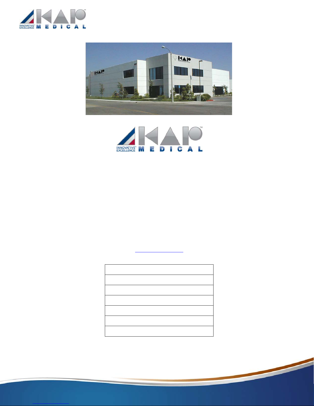
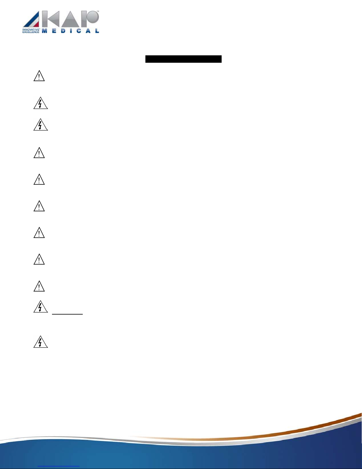
Weight Capacity:
Mattress Overlay: 360 lbs. (163 Kg.) maximum.
Standard Replacement Mattress: 360 lbs. (163 Kg.) maximum.
Bariatric Replacement Mattress: 1000 lbs. (455 Kg.) maximum.
Raised Side Bolstered Mattress: 360 lbs. (163 Kg.) maximum.
Bariatric Raised Side Bolstered Mattress: 1000 lbs. (455 Kg.) maximum.
Foam Aire Mattress: 360 lbs. (163 Kg.) maximum.
Universal Mattress (UM): 360 lbs. (163 Kg.) maximum.
Expandable Mattress (XM): 1000 lbs. (455 Kg.) maximum
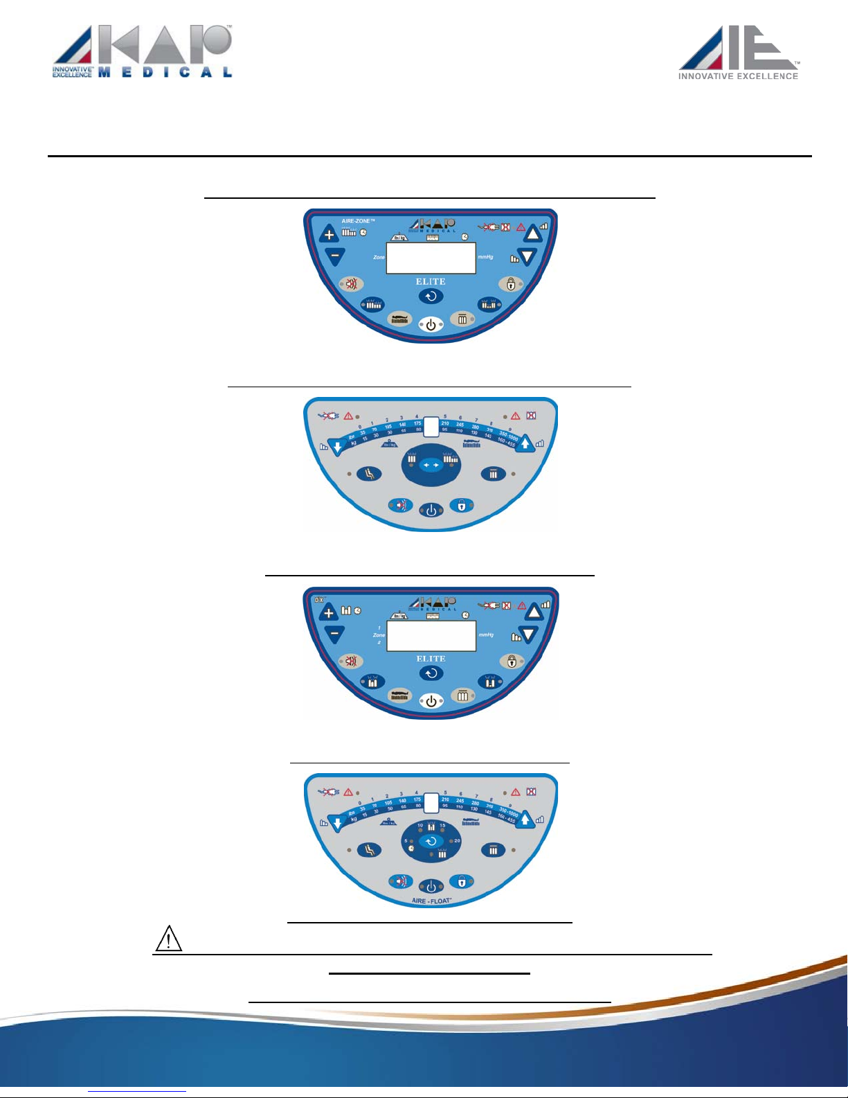
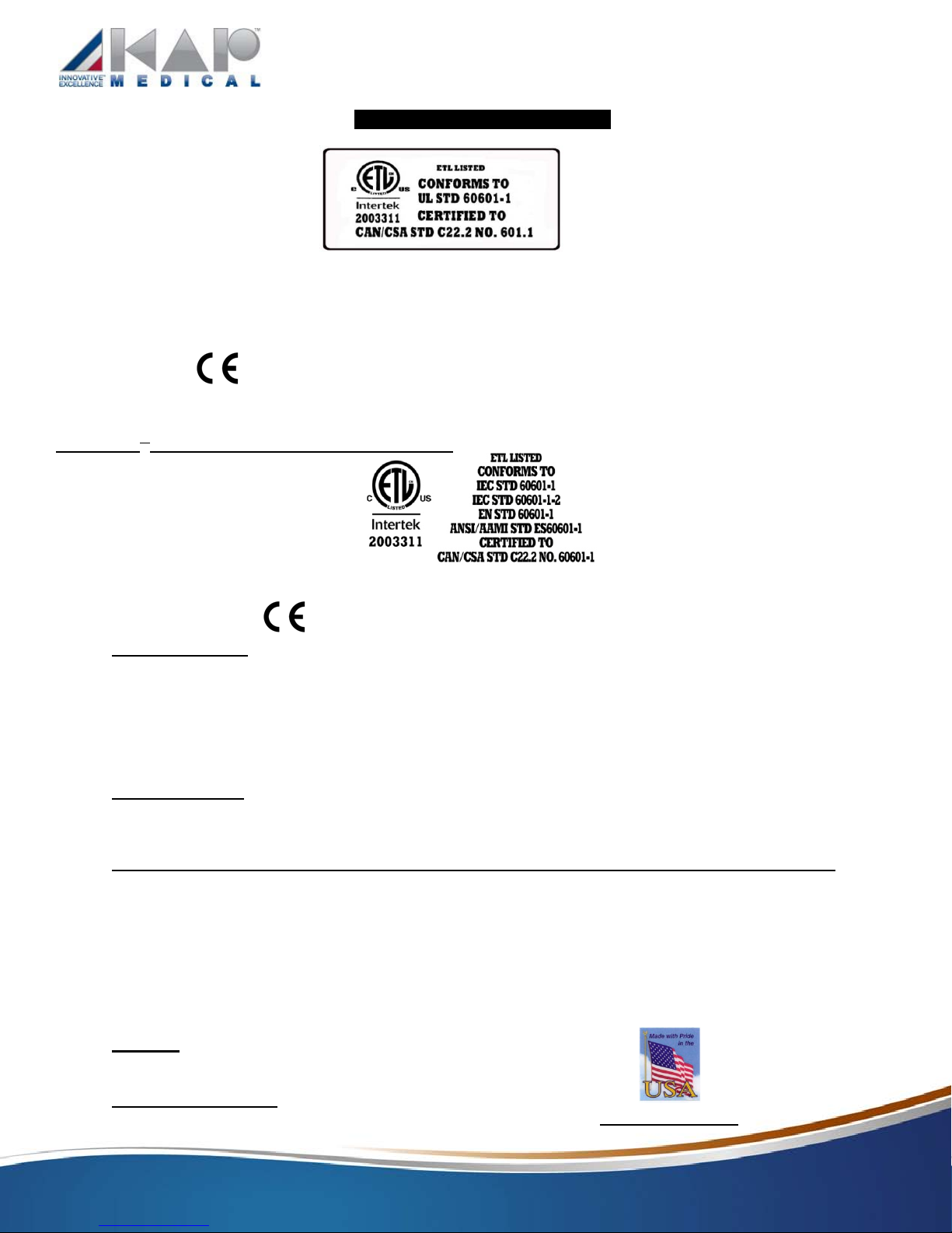
Pressure Zones: 5
AP Zones: 2 (K-4 models only)
Max Flow: 1275 LPM (45 CFM)
Support Surface Inflation Time: Within 60 seconds.
Patient Comfort Pressures / Alternating Pressure (K-3, K-4)
Soft Pressure: 6 ±5 mmHg
Firm Pressure: 32 ±5 mmHg
A/P Time: 1 Minute - 99 Minutes. (K-4 model only)
A/P Low Pressure: 10% - 75% (K-4 model only)
Patient Comfort Pressures / Alternating Pressure (K-3oem, K-4oem)
Soft Pressure: 7 ±5 mmHg
Firm Pressure: 32 ±5 mmHg
A/P Time: 5, 10, 15 and 20 minute A/P Time(s) (K-4oem model only)
A/P Low Pressure: 0% or 50% of high AP pressure setting. (K-4oem model only)
Patient Contact
Control unit and the mattress are lead free, mercury free and latex free,
Dartex top sheet is Halogen-free (bromide-free).
Mechanical Specifications: Control Unit (A)
Dimensions, LxWxH: 12” x 5 3/4” x 10.5” (30cm x 14cm x 27cm) (K-3, K-4 models)
13.5” x 11” x 6” (34cm x 28cm x 15cm) (K-3oem, K-4oem models)
Weight: K-3, K-3oem = 9 lbs. (4 Kg.) & K-4, K-4oem = 10 lbs. (4.5 Kg.)
Power Cord: 14’ long Hospital Grade
Connection: ½” flow magnetic quick connector (K-3, K-4 models)
½” flow single quick disconnect connector (K-3oem model)
½” (2) & ¼” flow quick disconnect connector coupling (K-4oem model)
Packaging: 1 piece per box

K-3 & K-4 Series Owner’s Manual
Page 6
Mechanical Specifications: Control Unit (A) (continued):
Air Filter Charcoal Air Filter
PLEASE CLEAN FILTER EVERY 3 MONTHS OR WHENEVER DIRTY. Remove 2 thumb screws and separate filter
foam from filter cover. Wash filter foam using soap and water. Dry and replace filter and filter cover on the unit and
fasten screws.
Support Surface (B) Standard, Bariatric & Bolstered:
Air cushions are high frequency heat sealed, liquid proof and washable. Base is liquid proof and washable.
Top Sheet is low friction, low shear, low force producing, breathable, liquid resistant and highly vapor permeable.
Material is nylon, Dartex, or 2-or-4-way stretch Derma-plus.1” or 2” bottom foam pad or 2” air pad on the bottom of
the air cushions enclosed in a cover.
The Foam AireTM
mattress has foam filled air cushions, enclosed in a foam base with foam side rails and foam
topper. The complete foam assembly is enclosed in a Kevlar fire barrier.
Description Inflated Dim. (LxWxH) Weight
Mattress (K-3 models): 80”x36”x10” 16 lbs.
(203x89x25.5cm) 7 Kg.
Mattress (K-4 models): 80”x36”x10” 18 lbs.
(203x89x25.5cm) 8 Kg.
72”, 76”, 84” & 88” in length mattresses available.
32”, 36”, 39”, 42”, 48”, 54”, 60” & 76” in width mattresses available
7”, 8” & 10” in height replacement mattresses available, along with 3” or 5” mattress overlays.
Packaging: 1 piece per box
Optional Patented Low Air Loss top sheet available.
Optional mattress with Kevlar lined fire barrier top sheet and mattress base available.
Environmental Specifications
Operating Conditions:
Ambient Temperature: 40°∼104°F (10°∼40°C)
Relative Humidity: 30% ∼75% Non-Condensing
Atmospheric Pressure: 700 hPa to 1060 hPa
Storage And Shipping Conditions
Ambient Temperature: -40°∼158°F (-40°∼70°C)
Relative Humidity: 10% ∼100%
Atmospheric Pressure: 500 hPa to 1060 hPa
Protection Against Harmful Ingress Of Liquids:
Ordinary Protection (IPXO)
Mattress Sanitation:
All components such as manifold, hose assembly, air cushions, top sheet, and foam base are interchangeable and
can be easily cleaned or detached for laundry. The Foam Aire mattresses have a Kevlar fire retardant barrier inside
the cover. Care should be taken if removing the cover for cleaning.
Disposal Requirements:
This equipment should be disposed of at your local Recycling Center (Non-hazardous waste) when it has reached
the end of its service life.

K-3 & K-4 Series Owner’s Manual
Page 7
SAFETY AGENCY APPROVALS
ETL Listed: 2nd
Edition
The standard for safety of Medical Electrical Equipment
Conforms To: UL STD 60601-1 with respect to Electrical Shock, Fire and Mechanical Hazards
Certified To: CAN/CSA STD C22.2 No. 601.1
CE Mark:
Class 1 equipment (Europe); Class 2 equipment (USA)
Optional 3rd
Edition Compliant Systems available
ETL Listed: 3rd
Edition
Class 1 equipment (Europe); Class 2 equipment (USA)
3rd
Edition CE Mark:
Flame Resistance:
Unit components meet UL 94V-0 and Mattress components pass California117.
Optional California TB 106, TB 129, 16 CFR 1632, 16 CFR 1633, BS 6607 (CRIB 5), BS 597-1, & BS-597-2
compliant mattresses lined with Kevlar fire barrier available (Kevlar lining based on flammability standard).
All Foam AireTM
mattresses are TB129, 1632 & 1633 compliant.
FDA Registration: FDA registered company as a manufacturer and as a contract manufacturer.
KAP MEDICAL’S quality system meets the requirements of:
FDA 21 CFR, PART 820- QSR-Current Good Manufacturing Practices (CGMP) for medical devices.
Products are FDA listed.
Health Canada Medical Device Licensed.
ISO 13485 certified company.
Medicare coded (SADMERC).
Patents:
US & International Patents Pending
Certificate of Origin:
All products are manufactured in Corona, CA, USA. MADE IN THE USA

K-3 & K-4 Series Owner’s Manual
Page 8
SAFETY INSTRUCTIONS
•Before operating your K-3 / K-4 series control unit, be certain the AC power available at your location matches the
power requirements printed on the product identification label on the back of the unit.
•To avoid electric shock, always plug the power cord of the control unit into a properly grounded power source.
•Do not insert items into any openings of the control unit. Doing so may cause fire or electrical shock by shorting
internal components.
•Do not spill liquids or food on or into the control unit. In the event of any spillage, immediately turn off the control
unit and disconnect it form the power source. Return the control unit for servicing to a factory authorized service center.
•Care should be taken such that the controls on the footboard of the bed frames are not obstructed by the K-3 / K-4
series control unit.
•Care should be taken such that the control unit is not blocked, and kept away from any heat sources or radiators
during the operation of the unit.
•Care should be taken such that the power cord of the control unit is not pinched, or has any objects placed on it.
Make certain it is not located where it can be stepped on or tripped over.
•Do not attempt to service the control unit except as explained in this operating instruction manual. Contact factory
for servicing instructions. Always follow operating and service instructions closely.
•Do not place the patient directly on the mattress without the top sheet.
•WARNING: Before opening the control unit enclosure, make sure the control unit is turned off and unplugged
from its power source. The control unit enclosure should only be opened by a factory authorized qualified service
technician.
•Smoking by the patient or anyone else around or on system is prohibited. K-3 / K-4 series system uses room air
for circulation through the mattress. Smoking will contaminate the system.

K-3 & K-4 Series Owner’s Manual
Page 9
BED RAIL ENTRAPMENT RISK NOTIFICATION
NOTICE TO PATIENT, PATIENT’S FAMILY AND/OR PRIMARY DAY-TO-DAY CAREGIVER
DO NOT use this product without first completely reading and understanding this Bed Rail Entrapment Risk Notification
and any additional instructional material such as owner’s manual, instruction sheets and on-product warnings supplied with
this product. If you are unable to fully understand this Bed Rail Entrapment Risk Notification, the on-product warnings or
any additional instructional materials, contact the patient’s health care provider and/or your equipment provider before
using this equipment. Failure to understand and comply with the information contained in this Bed Rail Entrapment Risk
Notification can result in serious injury or death.
Entrapment within the bed rail Entrapment under the bed rail Entrapment between the Entrapment between the
bed rail and mattress head or foot board and the
end of the mattress
Entrapment under the bed rail at the ends Entrapment between split bed rails Entrapment between the end of
of the bed rail the rail and the side edge of the
headboard or foot board
RISK OF ENTRAPMENT
Bed Rail Entrapment is a known risk in the use of bed’s equipped with bed rails.
Every patient is unique. Only the patient’s medical care provider is familiar with the patient’s unique medical condition and
needs. Only the patient’s medical care provider and/or the dealer from whom you obtained this equipment, upon proper
assessment of the patient’s medical condition and needs, can evaluate whether this equipment is appropriate for use by any
particular patient and assist the patient, the patient’s family and/or the patient’s primary day-to-day caregiver in assessing
the Risk of Entrapment.
Proper patient assessment, equipment selection, frequent patient monitoring, and compliance with instructions, warnings
and this Bed Rail Entrapment Risk Notification is essential to reduce the risk of entrapment.
Accessories have been developed in the industry to reduce the openings in existing bed systems that could cause
entrapment. Any modification through the use of accessories must be used in conjunction with proper patient assessment
prior to intervention. For a full discussion on this topic, see the Hospital Bed Safety Workgroup’s “A Guide for Modifying
Bed Systems and Using Accessories to Reduce Risk of Entrapment” found at http://www.fda.gov
.
Conditions such as restlessness, mental deterioration and dementia or seizure disorders (uncontrolled body movement),
sleeping problems, and incontinence can significantly impact a patient’s risk of entrapment, Pediatric patients or patients
with small body size may also have an increased risk of entrapment.

K-3 & K-4 Series Owner’s Manual
Page 10
BED RAIL ENTRAPMENT RISK NOTIFICATION
•Bed rails are intended to prevent an individual from inadvertently rolling out of bed, provide assistance to a patient when
repositioning and to provide a sense of security. NEVER use bed rails for restraint purposes where “restraint” means
preventing or hindering the patient within the bed from exiting the bed as they wish. Use of rails as a means of restraint
significantly increases a patient’s risk of entrapment.
•Bed rails are intended to be used as a pair in a bed system. When in use, both side rails must be in the up position,
except when the patient is entering or exiting the bed. Use with one side rail up and one side rail down could create an
increased risk of entrapment.
•Bed rails and/or their mountings should not be used if they are bent or otherwise deformed. Bent or deformed bed rails
and/or bed rail mountings increase gaps and increase the risk of entrapment. DO NOT place pressure upon bed rails
while moving the bed. Although bed rails are not rated to any specific patient weight limitation, the bed rails or their
mountings may become deformed or broken if excessive side pressure is exerted on the bed rails.
•Mattress overlays or active therapeutic support surfaces (TSS), which support the patient on an air mattress or
specialized foam layer, may present an increased risk of entrapment for some patients. The benefit of TSS product use
must be weighed against the potential increased risk of entrapment. The risk judgment must be performed by a medical
professional.
The U.S. Food and Drug Administration in partnership with the U.S. Department of Veterans Affairs, Health Canada’s
Medical Devices Bureau and representatives from national health care organizations and provider groups, patient advocacy
groups, and medical bed and equipment manufacturers including the Hospital Bed Safety Workgroup, a collection of experts
from the United States FDA, health care professionals and manufacturers of hospital beds, published guidelines regarding
body part dimensions as they relate to a bed system’s safety. These guidelines, “Hospital Bed System Dimension and
Assessment Guidance to Reduce Entrapment” contain additional information on the risk of entrapment. Visit the FDA
website at http://www.fda.gov and search for “bed rail entrapment” to learn about the risk of entrapment or to view the FDA
guidelines document.
The above statements are not intended to be a complete or comprehensive list of all risks of entrapment. KAP Medical
recommends that whenever bed products are used that the patient, the patient’s family and/or the patient’s primary day-to-
day caregiver discuss entrapment risks with the patient’s medical care provider.

K-3 & K-4 Series Owner’s Manual
Page 11
UNIT OVERVIEW
{Figure 1, Page 15}
These Air Therapy Systems are designed to provide continuous air therapy support at required patient comfort levels and
are used to inflate an overlay mattress or replacement mattress system. The Thermoplastic 94V-0 fire retardant enclosure
houses a blower, main PCB, display panel, a short circuit /over voltage protection with dual fuses, a quick connection and
disconnection (CPR deflation) coupling connector (R) with ½” flow ports with RTPM (real time pressure monitoring)
technology sensors, and a 14’ (427 cm) long detachable 16 AWG hospital grade power cord (Q).
Unit Label Location(s):
K-3 AIRE-ZONE™ / K-4 D3X™ (DecubeXTM
)
K-3oem EZ-AIRE™ / K-4oem AIRE-FLOAT™

K-3 & K-4 Series Owner’s Manual
Page 12
Unit Display Labels:
Refer to the “Explanation of Symbols Used” chart on page 13 for a cross reference of Display Key descriptions.
K-3 AIRE-ZONE™
™
™
K-3oem EZ-AIRE™
K-4 D3
X™
K-4oem AIRE-FLOAT™

K-3 & K-4 Series Owner’s Manual
Page 13
EXPLANATION OF SYMBOLS USED ON THIS DEVICE
Not all features included with each model.
FUNCTION
SYMBOL
EXPLANATION
POWER (SB)
Turns unit On / Off.
Green = On Amber = Standby
SOFT / FIRM (K) or Up or Down key adjusts patient comfort pressure levels.
PLUS / MINUS (L) Adjust “+/-” to set various therapy times and patient
settings.
SET-UP (H)
Set Patients height and weight.
MODE (M)
Select between Therapy Modes.
(K-3, K-4, K-4oem)
SELECT (S)
Select between Therapy Modes.
(K-3oem)
ALARM
SILENCE (AS)
Alarm Silence – mutes audible alarm.
LOCK OUT (LO) Locks out all control unit functions to prevent tampering.
(Max Inflate still available on K-3 & K-4)
PULSE (N)
(WAVE)
Selects Pulsation mode on.
Continuous Low Air Loss during Pulse mode.
PAN (Y)
Selects Pan mode on.
Continuous Low Air Loss during Pan mode.
STATIC (T)
Selects Static Therapy mode.
Continuous Low Air Loss during Static mode.
ALTERNATING
PRESSURE (AP)
Selects A/P mode.
Continuous Low Air Loss during Pulse mode.
10 MIN A/P (D)
Default AP -Preset 10 min Alternating Pressure Therapy.
Continuous Low Air Loss during A/P mode.
FOWLER (U)
Fowler Mode. The pressure will increase to prevent the
patient from bottoming out.
MAX Inflate (W)
Inflates mattress rapidly (15 minute timer)
Continuous Low Air Loss during A/P mode.
POWER FAIL (PF)
In the event of power failure or if the hose is disconnected,
an audio/visual alarm will sound.
LOW PRESSURE (LP)
Indicates the point of attachment of the equipment to earth (Grounding Point).
Attention: Instructs end user / care giver / operator to refer to the manual.
Indicates that the degree of protection against electrical shock is TYPE BF.
Not for use in presence of flammable anesthetics.
Consult Instructions for Use
Waste electrical and electronic equipment (recycle).
Risk of electrical shock. Do not remove back cover.

K-3 & K-4 Series Owner’s Manual
Page 14
EXPLANATION OF SYMBOLS USED ON THIS DEVICE (CONTINUED)
Not all features included with each model.
SYMBOL
EXPLANATION
No Sharp Objects
Low Heat Setting
Do Not Dry Clean
Do Not Bleach
No Open Flames
Normal Cycle
Do Not Iron
Latex-Free
Bolstered Mattress
Even Bolstered Mattress
Bolster Deflate
Mattress Deflate
Air Pad Deflate
CPR Deflate
Length Expansion Regulator
Width Expansion Regulator
Universal Mattress Regulator
Heel Zone Regulator

K-3 & K-4 Series Owner’s Manual
Page 15
MATTRESS OVERVIEW
(Support Surface) {Figure 1, (B), Page 15}
Self-contained mattress replacement system/ mattress overlay system (B) with easily detachable
components for cleaning. Flame retardant, water repellant, mildew resistant, low friction and low shear, 5” or
8” high (inflated) detachable lateral tubular air cushions (T) (16~22). Detachable zippered or strapped highly
breathable, reusable, quilted Top Sheet composed of two layers; Top layer is made out of urethane coated 70
Denier nylon, (Dartex, 2-way stretch, or 4-way stretch, optional). Bottom layer is made out of quilted
material. It is flame retardant, water repellant, vapor permeable, anti-microbial, low friction and low shear (E).
2” safety air pad or convoluted foam pad enclosed in a foam/air pad base (C) to support the patient in the
event of loss of air pressure in the mattress. The mattress has a hose assembly (V) with easy to use quick
connect and disconnect connector coupling (R).
Figure - 1
Mattress System
Overlay Mattress System Bolstered Mattress System

K-3 & K-4 Series Owner’s Manual
Page 16
Mattress Weight Capacity:
NOTE: See bed frame manufacturer’s manual for bed frame weight rating.
K-3 & K-4 SERIES systems are used for patients who weigh between 35 lbs. and 1000 lbs.
(15 Kg. and 455 Kg.)
Replacement Mattress Standard System: 36” wide, 35-360 lbs. (15-163 Kg.)
Bariatric Mattress: 1000 lbs. (455 Kg.) maximum
Raised side Bolster Mattress: 360 lbs. (163 Kg.)
Bariatric Raised side Bolster Mattress: 1000 lbs. (455 Kg.)
Foam Aire Mattress: 360 lbs. (163 Kg.)
Universal Mattress (UM): 360 Lbs. (163 Kg.)
Expandable Mattress (XM): 1000 lbs. (455 Kg.)
WARNING:
It is highly recommended that the K-3 / K-4 series SYSTEM always be installed on medical bed frames that
are equipped with standard hospital side rails or assist rails. Please raise all 4 side rails on the bed and
lock them in position after the patient is on the mattress. Health care professionals assigned to each case
should make the final determination whether side or assist rails are warranted after assessing patient risks
of entrapment and falls in accordance with State patient restraint legislation or facility interpretation of
such legislation.
Check that all air hoses and power cord are clear of moving bed components before placing a patient on
the bed and that the mattress system is fully inflated. Operate all bed frame motorized functions through
their full range of motion to be certain that there is no pulling, interference or pinching.
Mattress MUST fit bed frame and side rails snugly to prevent patient entrapment. See {Figure 1, Page 15}
UNPACKING THE SYSTEM
Note: When opening the large system box or the small control unit box, ensure that the object used to open
the box does not penetrate and damage the components inside.
Components Supplied:
•Complete Replacement Mattress System Box
1 Control Unit box & 1 Mattress
•Overlay Mattress System Box
1 Control Unit & 1 Overlay Mattress
•Control Unit Box
1 Control Unit
1 Operating Instruction Manual
1 Power Cord
•Foam Aire Mattress Box
1 Foam Aire Mattress
1 Control Unit (if ordered with Mattress)
1 Hose Assembly (if ordered with Mattress)
Unpacking and Inspection:
•Before accepting and signing for your shipment, please inspect the box or boxes for external and internal damage.
Verify that the number of boxes listed on the packing list matches the number of boxes received. Verify that no
components in your shipment are damaged or missing. Report any missing boxes, components and or damage to the
transportation carrier immediately.

K-3 & K-4 Series Owner’s Manual
Page 17
MATTRESS SYSTEM SET-UP
Note: Make sure that the hose end of the mattress is towards the foot of the bed.
Note: When installing the KAP Medical mattress system, do not exceed the manufacturers rated weight of the
mattress or the bed frame. See the bed manufacturer’s manual for bed frame weight rating.
Note: Make sure the CPR, bolsters and air pad plugs are connected and locked in place before inflating the
mattress
Note: Care should be taken such that the air inlet vent on the control unit is not covered, and the control unit is
not placed on the floor in such a manner that it is a hazard for flow of traffic or lowering of bed frame.
Note: Before using the KAP Mattress System, please remove current mattress, mattress replacement systems or
overlay systems from the bed.
Overlay Mattress system:
•When using the Overlay mattress system, care should be taken such that the overlay is placed directly on an
existing 3” to 5” foam mattress.
•Unroll the Overlay and place it on the foam mattress.
•There are two elastic straps, one at the head and the other at the foot section. Two long straps on one side and two
short straps with buckles on the other side of the overlay. Insert head and foot elastic straps around the foam
mattress. Loop each long side strap around the foam mattress and fasten it securely to the short strap on the other
side using the buckle.
Replacement Mattress system:
•When using the replacement mattress system, care should be taken such that the mattress is placed directly on the
bed frame. {Figure 1,(B), Page 15}
•Unroll the Replacement Mattress and place it on the bed frame (BF).
•There are ten nylon black straps with buckles (F), two straps at the head of the mattress, two on the foot of the
mattress, and three on each side of the mattress. Loop each strap around the bed deck and secure using the
buckle (D-ring). Note: Make sure Head, Knee and Foot sections of the bed can be raised and the straps are
secured to the deck and not to the frame. Once the mattress is strapped, tuck the exposed straps under the
mattress.
•Pull out the hanger on the back of the control unit (A) and suspend the control unit from the footboard (FB) of the
bed (BF). If the bed you are using does not have a footboard, place the control unit (A) on its base (not on its back
where the filter is located) on a flat surface in front of the bed near the foot of the bed frame (BF).
•Uncoil the power cord (Q) and plug the cord into the appropriate AC power source (X), which is properly grounded.
Plug the other end of the power cord into the control unit and press it in place.
Note: Care should be taken such that the power cord of the control unit is not pinched, or has any objects placed
on it. Ensure it is not located where it can be stepped on or tripped over. Make sure the control units power inlet
connection is positioned to easily disconnect the power cord from the unit.
•Connect the mating connector (R) on the mattress hose assembly (V) into the insert on the control unit connector
and lock it in place.
Note: ELITE Series-Make sure the magnetic connector has a good connection. Also, care should be taken such
that the mattress hose is freely suspended without being pinched or kinked.

K-3 & K-4 Series Owner’s Manual
Page 18
•Make sure the CPR, bolsters and air pad plugs are connected and locked in place before inflating the mattress.
•Make sure the left and the right side safety air bolsters (if available) as well as the bottom safety air pad are fully inflated
and up to the correct operating pressure and firm prior to placing a patient on the mattress.
•Make sure the heel regulator valves/knobs in the Universal Mattress (UM) and Expandable Mattress (XM) are in proper
position
OPERATING INSTRUCTIONS
Note: Not all functions are available on all models. {Display labels – page 12 & Figure 1- Page 15}
INITIAL POWER UP
•(K-3 ELITE, K-4 ELITE) During initial power up when power cord (Q) is plugged into the power source (X), the control
unit will display “KAP MEDICAL, LOW AIR LOSS SYSTEM” on K-3 system and “KAP MEDICAL, ALTERNATING LOW
AIR LOSS SYSTEM” on K-4 system for a brief moment and then goes through a system initialization routine for a few
seconds. Once the routine is completed the display (D) will read “KAP MEDICAL STAND BY”.
•(K-3oem, K-4oem) During initial power up when power cord (Q) is plugged into the power source (X), the control unit will
display illuminated amber light indicating that the unit is in Standby mode.
POWER (SB)
•Press Power key, the (amber) Standby LED will turn off and the (green) LED turns on. The blower will turn on.
LOW AIR LOSS
•Continuous Low Air Loss relief is provided at all times when the K-3 or K-4 series system is powered on.
MAX INFLATE (W)
•Press MAX Inflate (W) key, the (green) LED will turn on. This mode is used to rapidly inflate the mattress. During this
mode a series of beeps will sound every 3 minutes as a reminder that MAX Inflate mode has been activated. During this
mode, the entire mattress will be pressurized to 35 ±5 mmHg. The mattress (B) will inflate to its normal size within 60
seconds. MAX Inflate mode will deactivate after 15 minutes.
THERAPY (STATIC) (T)
•To set Static mode press (S) Select key (K-3oem model only) or (M) Mode key until the Static mode
indicator light illuminates and the screen displays THERAPY. The unit will go into “THERAPY” mode.
•In THERAPY mode all the air cushions in the mattress will be maintained at the same pressure and can be adjusted to
the desired patient comfort control level.

K-3 & K-4 Series Owner’s Manual
Page 19
PATIENT COMFORT CONTROL LEVEL (K) or
•The system is designed for patients weighing between 35 ~ 1000 lbs. (15 Kg. ~ 455 Kg.). By pressing the Comfort
Control Keys (K) towards the SOFT position (down arrow) reduces the pressure setting, and the FIRM position (up
arrow) increases the pressure. The patient comfort pressure ranges from SOFT 6 ±5 mmHg to FIRM 32 ±5 mmHg.
Depending on the desired patient comfort level, the controller will increase or decrease the speed of the air blower to
provide the appropriate air flow into the mattress to maintain the desired pressure in the mattress.
•Once the mattress is inflated to its normal size, lay the patient on the mattress and set the Comfort Control Key(s)
(Soft/Firm) to the desired patient comfort level. Wait 2 minutes for the mattress pressure to stabilize and verify the
appropriate pressure required to support the patient by performing a simple “four finger check”. Make sure that the
patient is lying flat on their back in the center of the mattress. Place four fingers between the air cushions directly
underneath the sacral region of the patient’s body. There should be a minimum of 3 to 4 finger width clearance
between the bottom of the patient and the safety foam base, (on an overlay there is no safety foam base). Repeat this
procedure until the desired patient comfort pressure is achieved.
ALTERNATING PRESSURE (AP) (K-4 models only)
•To set Alternating Pressure (AP mode), press the (M) Mode key to light up the appropriate AP times 5, 10, 15 or 20
minutes. (K-4oem model)
•To adjust the low pressure zone of the Alternating Pressure therapy, follow the next steps:
•(Perform in Stand-By mode) Press and hold “Mode” & “Fowler” keys until unit beeps. (Approx. 3 seconds).
•7- segment will display “0” (0% mmHg of high pressure setting) or “5“ (50% mmHg of high pressure setting)
•To end routine and accept setting, press “Power” key.
•Routine will auto time out in 30 seconds if no key is pressed.
•Turn on control unit and select Alternating Pressure mode.
•To set Alternating Pressure (AP mode), press the (AP) key, using the (L) “+/-” key select the desired AP time, 1 to 99
minutes. (K-4 Elite model)
•To adjust the low pressure zone of the Alternating Pressure therapy, follow the next steps:
•During Alternating Pressure therapy, press the “Mode” key; A/P settings will be displayed on the screen.
•Use the (L) “+” and “-“ keys to adjust the Low AP percentage value (10% to 75% of high pressure setting)
•Unit will time out and setting will be set automatically within 15 seconds.
•In AP mode, alternate air cushions will inflate to the patient comfort pressure while those cushions between the inflated
air cushions will deflate.
This manual suits for next models
3
Table of contents