Katadyn PowerSurvivor 80E User manual

PowerSurvivorTM 80E
Endurance Series
12-Volt & 24 Volt
Watermakers
OWNER`S MANUAL

II

Thank you…
for purchasing a Katadyn PowerSurvivor 80E watermaker. It was built to rigorous
specifications, and designed to produce potable freshwater from clean seawater using
minimal power. It is simple to install and operate and, with reasonable care and
maintenance, will provide years of useful service.
Please…
before installing or operating your watermaker, take the short time needed to read this
User’s Manual in its entirety. This small investment of time will help assure many years of
trouble-free operation from your system. We’ve worked hard to provide you with a reliable
product that is affordable, compact, simple to operate and easy to maintain—the rest is up
to you.
Contact us:
Be sure to fill in the enclosed warranty card and return it to us as soon as possible. This is
required to fulfill the terms of your warranty. For Customer Service, or information about
this and other products from Katadyn, please use our toll-free phone numbers or visit our
website at www.katadyn.com.
Katadyn North America
6325 Sandburg Road, Suite 400
Minneapolis MN 55427
Phone: 800-755-6701 or 763-746-3500
Fax: 800-548-0406 or 763-746-3540
Website: www.katadyn.com
Customer Service / Technical Support:
800-755-6701 or 763-746-3500
(International Collect Calls Accepted)
Email: [email protected]
We suggest you keep a record of your Katadyn dealer’s name, contact information, and the serial
number of your watermaker in the space below:
Dealer Name:
_________________________________________________________________
Address:
_________________________________________________________________
Phone/Fax/Website:
_________________________________________________________________
Serial Number:
_________________________________________________________________
III

Table of Contents
System Discription......................................................................................................1
Product Specifications ...............................................................................................2
Energy Recovery.........................................................................................................3
Installation ...................................................................................................................4
Installation DOs ..................................................................................................4
Installation DON`Ts.............................................................................................4
Installation Procedures......................................................................................5
Using your Watermaker..............................................................................................7
Special Conditions .............................................................................................9
Maintenance and Service ......................................................................................... 10
Pump Maintenance........................................................................................... 10
Prefilter Maintenance........................................................................................ 11
Membrane Storage, Preserving & Cleaning ................................................... 12
Seal Replacement............................................................................................. 15
Troubleshooting Flowchart.............................................................................. 21
Appendix.................................................................................................................... 22
Glossary ............................................................................................................ 22
Diagrams ........................................................................................................... 23
Kits & Accessories ........................................................................................... 28
Service Log ....................................................................................................... 29
WARRANTY....................................................................................................... 31
IV

System Description
The Katadyn PowerSurvivor 80E watermaker system has several components. Refer to the
System Diagram (Figure A-1) in the Appendix for an overview of the components of the system
and their interconnections.
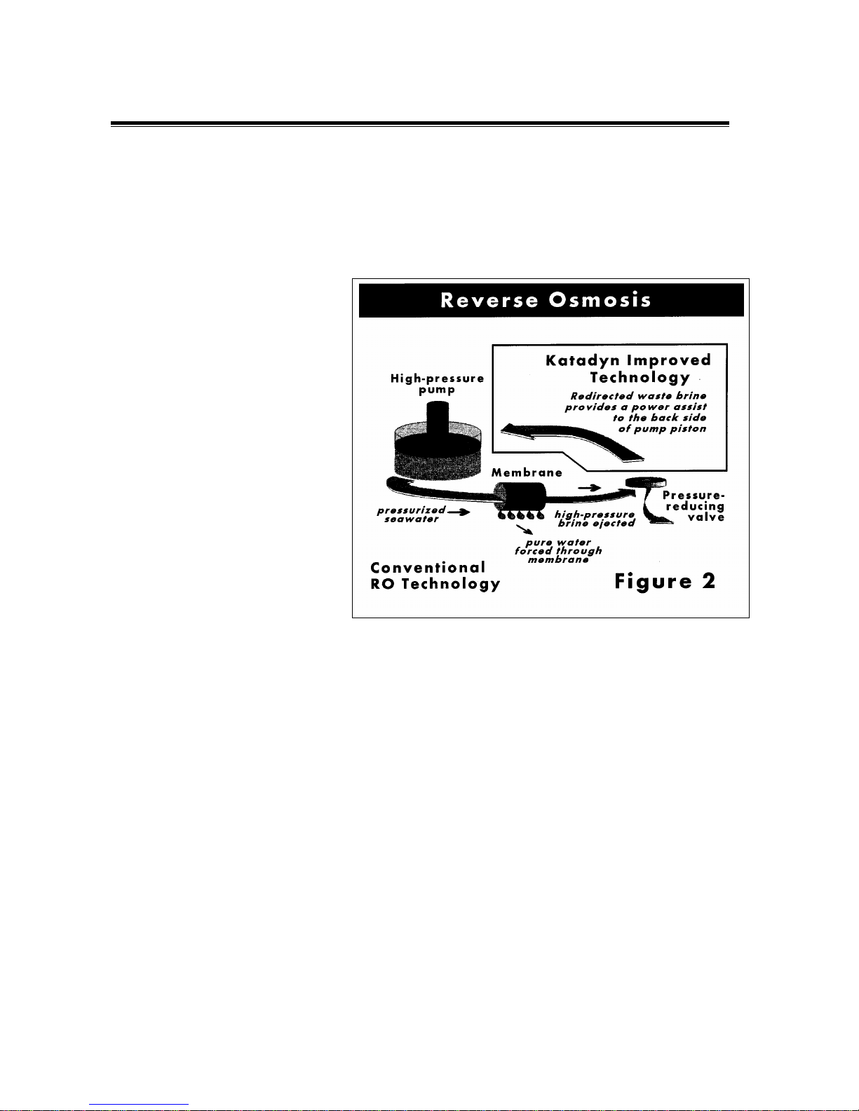
Motor/Drive/Pump & Membrane Housing: At the heart of the watermaker system
is a high-pressure, positive-displacement pump. The pump is powered by a reliable 12 (or 24)
VDC electric motor. An oil-bath gearbox (drive assembly) converts the rotary motion of the
electric motor to a powerful, reciprocating, linear motion for driving the pump piston. The pump
pressurizes input seawater to approximately 800 psi (pounds per square inch) and forces
product freshwater through a semipermeable membrane located in the membrane housing. The
motor, gearbox and pump have been integrated into a single, compact piece of equipment—
with low power consumption, quiet operation and a small footprint. The membrane assembly is
a separate unit which allows it to be mounted in a convenient location.
Prefilter Assembly: The prefilter assembly consists of one prefilter housing and a
standard 30-micron prefilter element constructed of polyester fibers. Two standard elements
ship with each system. In some exceptional circumstances, an optional second prefilter
assembly with a 5-micron prefilter element may be needed (see Kits & Accessories). The
prefilter assembly is separate unit which allows it to be installed in a convenient and accessible
location.
Valves: Two high-quality plastic 3-way valves are supplied. The prefilter 3-way valve selects
between (1) seawater input for normal operation and (2) an alternate intake line for inputting
membrane preservative or a cleaning solution. The product 3-way valve allows easy routing of
product water to either (1) a freshwater collection tank for normal operation or (2) a drain
location for discarding during initial startup, testing, preservation or cleaning operations.
Hoses and Hardware: Each PowerSurvivor 80E watermaker is shipped with appropriate
hoses and hardware sufficient to perform a normal installation. This includes two high-pressure
hoses (3’ and 5’) for carrying pressurized seawater from the pump to the membrane housing
and reject brine water from the membrane housing back to the pump. The 1/2" I.D. reinforced
plastic hose is used for seawater intake and reject brine. The smaller, 1/4" I.D. clear plastic
hose is for routing product freshwater. There are also hose clamps and mounting bracket
hardware for the prefilter assembly and membrane housing, and a TDS (Total Dissolved Solids)
meter for testing and monitoring the quality of product freshwater.
Customer-supplied Equipment: Every installation represents a unique challenge!
You or your installer will need to provide:
1. a reliable source of clean seawater for input to the prefilter 3-way valve
2. plumbing to an appropriate drain location for the reject brine water
3. a plumbing solution for your freshwater collection tank
Our Promise: Every Katadyn PowerSurvivor 80E watermaker includes a three-year factory
warranty and a long history of outstanding customer support. Our reputation for providing a
quality product, along with service when and where you need it, is unequaled in the industry. Of
course, you may never need us—but, if you do, we’ll be there.
1

Product Specifications
Power Requirements: 8 amps @ 12 VDC; 5 amps @ 24
VDC*
Construction: 316 Stainless Steel Pump Housing
Configuration: Modular
Rate of Water Production: 3.4 U.S. gal./hr. (12.9 liters/hr.)
±15% @ 13.8 VDC
Feed Water Flow Rate: 34 U.S. gal./hr. (129 liters/hr.)
Pump Weight: 34 lbs. (15.4 kg.)
Pump Height: 6.2" (15.7 cm.)
Pump Length: 17.5" (44.5 cm.)
Pump Width: 13.5" (34.3 cm.)
Membrane Housing Dimensions: 31" x 2.5" (79 cm. x 6.4 cm.)
Prefilter Housing Dimensions: 12" x 6" (30 cm. x 15 cm.)
*The electric current requirement is an average figure. Instantaneous current will vary during a
complete cycle of the pump.
2

Energy Recovery
The technology behind Katadyn reverse osmosis watermakers
Reverse osmosis desalination was first developed over three decades ago. It was a major
breakthrough in desalting technology, but the original process required a lot of power. By
recovering 90% of the energy lost in conventional reverse osmosis systems, we’ve made small
desalinators practical, so you can have freshwater when and where you need it.
Conventional Reverse Osmosis Desalination
The lower left portion of Figure 2 shows the basic principle of reverse osmosis desalination.
When saltwater is forced through a
semipermeable membrane at high
enough pressure—typically 800
psi—pure water will pass through
the membrane, but salts will not.
The membrane acts as a barrier to
contaminants such as salts,
viruses and bacteria, separating
hem from the pure water.t
When seawater is forced against a
membrane, only 10% passes
through as pure water. In a
conventional system, the
remaining waste brine stream, still
under high pressure, passes
through a pressure-reducing valve
and is discharged overboard. For
every gallon of pure water made,
up to ten gallons of seawater must
be pressurized! Therefore, 90% of
the energy used in conventional
reverse osmosis is lost!
Energy Recovery Makes It Possible The upper right portion of Figure 2 illustrates
how Katadyn systems are configured to recover and effectively re-use the energy wasted in
conventional reverse osmosis. The waste brine stream contains up to 90% of the energy
expended. By recovering this energy, we are able to dramatically reduce the power needed to
esalt seawater.d
To do this, we developed and patented a high pressure energy recovery pump. It recycles the
high-pressure brine by redirecting it to the backside of the pump’s piston. By balancing the
opposing force on the piston’s front side, the brine provides a power assist to the pumping
operation. Seawater can then be pressurized with much less effort.
Katadyn Watermakers Katadyn watermakers are simple, energy efficient and easy to
use and maintain. The PowerSurvivor 80E incorporates the latest advances in watermaker
technology, featuring an improved oil-bath drive assembly, an all-316 stainless steel pump
body, and simplified construction for easier and less frequent maintenance.
3

Installation
Do it right the first time and reap the rewards
The PowerSurvivor 80E watermaker utilizes a low-volume, high-pressure, positive
displacement pump. Unlike the centrifugal pumps found in some systems, a positive
displacement pump is self-priming. It can also draw water when mounted several feet above
the waterline of a vessel. Thus, the watermaker may be installed in almost any location and
orientation.
The most important part of a good installation is proper planning. Although the design and
operating requirements of the PowerSurvivor 80E allow much latitude for equipment location,
there are several cautions and suggestions you should consider before proceeding with an
installation. Installation DOs
When choosing a location for the watermaker drive/pump or membrane assembly:
5Avoid areas with excessive heat. Ambient temperatures above 105°F (40° C) exceed
the ratings for the electric motor, and excessive heat can damage or destroy the
membrane.
(Note: Most engine rooms get hotter than 105° F!)
5Choose a dry area. The motor/drive assembly is not waterproof and can corrode.
5Choose an area free of fuel vapors. The electric motor is not vapor-proof and should
not be operated if explosive or flammable materials are present!
5Find a location which allows comfortable access for routine inspection and servicing.
In addition, you should:
5Install the pre filter assembly in an easily accessible location. It needs regular
(sometimes daily) inspection and maintenance. For ease of routine maintenance, the
choice for this location is probably the single most important decision you will make—
plan it carefully!
5Provide a shutoff valve or seacock in the seawater intake line.
5Install a coarse strainer in the seawater intake line.
5We recommend using properly sized ring terminals and a terminal strip near the pump
to connect electric power. This allows for easy testing, removal and servicing when
required. Installation DON’Ts
9Don’t use a thru-hull installed high on your vessel’s hull for your source of seawater
intake. This is especially important for sailboats. Even a normal amount of heel when
under sail can cause the thru-hull to be out of the water, allowing air into the intake
system. A rolling anchorage can do the same.
9Don’t locate the pump assembly above gear or materials that could be damaged if it
leaked.
9Don’t locate the pump assembly near to sleeping quarters, bunks, or other areas that
are normally “quiet” areas for yourself or crew members.
4

Installation Procedures
Although every installation has its custom as-
pects, the following general instructions should be
useful to the typical installer. Refer to Figure A-1
(in the Appendix) for information on part identifica-
tion and system connections.
1. Install Pump: After reading the comments
on the preceding pages, decide on a location for
the pump and drive assembly. It should be
mounted with the pump and drive side by side
horizontally. The reason for this requirement is to
avoid two problems:
•If the pump develops a seawater leak and
is located directly above the drive
assembly, the drive assembly and/or
electric motor may be damaged (Figure 3,
left).
•If the drive assembly develops an oil leak and is located directly above the pump, oil
may find its way into the pumping system and damage the membrane (Figure 3, right).
We recommend securely thru-bolting the pump/drive assembly to a sturdy bulkhead or
platform, using corrosion-resistant 1/4" fasteners with flat washers (See Figure A-1). Pick a
location that allows ample space for routing the required hoses and electrical wires to the pump
and motor.
2. Connect Electrical Power to
Pump: To provide 12 (or 24) VDC electric
power to the motor, use a minimum of 14
gauge / 12 VDC (16 gauge / 24 VDC)
stranded copper wire. We recommend 12
gauge / 12 VDC (14 gauge / 24 VDC) or
larger wire for distances over 20 feet. Tinned,
stranded copper wire is preferred for marine
installations and is available in most marine
hardware stores. Figure 4 shows a typical
electrical power configuration.
3. Mount Pre filter Assembly and
3-Way Valve: Lightly coat the male
threads of the middle port of the pre filter 3-
way valve with a non-hardening, paste-type
thread sealant (e.g., Permatex®) to assure an
airtight seal. (Note: Teflon tape is not
recommended.)
M
white
black
12 V or 24 V
Battery or Power
Source
red
black
-
+
Figure 4
Dimension of the cable:
14 gauge / 12 V
16 gauge / 24 V
Terminal
Strip
Fuse and Circuit
Breaker:
12 V = 15 A
24 V = 10 A
Basic Electrical Diagram
1. Carefully thread the middle port of the pre filter 3-way valve into the “IN” port of the pre
filter housing. Do not over tighten this connection. When assembled correctly, the long
axis of the 3-way valve should be vertical (See Figure A-1).
2. Fasten the supplied right-angled mounting bracket for the pre filter assembly to a
bulkhead. Orient it so the pre filter assembly will be vertical, with the bowl underneath.
We recommend that it be thru-bolted with corrosion-resistant hardware.
3. Screw the top of the pre filter housing to the bracket with the supplied screws. One port
of the pre filter 3-way valve should project above the housing through the notch in the
mounting bracket.
5

4. Install Seawater Intake Plumbing: There are two common approaches to
providing the seawater intake circuit:
•Tee into an existing seawater intake (e.g., engine cooling water or manual seawater
pump inlet).
•Install a dedicated thru-hull for the watermaker.
Either of these configurations should meet the following criteria:
•It should be at a low point on the vessel’s hull, to minimize the chance of air intake
during heeling or rough conditions.
•The thru-hull should be a minimum of 1/2" I.D., and possibly larger if it is a shared inlet.
(Note: If there is the possibility that in the future you will want to upgrade by adding a
second PowerSurvivor 80E to implement redundant systems—you should consider
substituting 5/8" I.D. hoses and hose fittings during your initial installation).
•An easy-to-reach seacock should be installed on the thru-hull immediately inside the
hull.
•A coarse seawater strainer is strongly recommended. It should be easy to reach and
clean.
The easiest and most commonly used approach is to tee into an existing seawater intake
system. Because the flow rate and volume of seawater intake for the PowerSurvivor 80E are
both extremely low, the pump can be adequately supplied by most pre-existing intakes—even
inlets that operate at modest negative pressures, such as the cooling water inlet for an engine
or generator.
When teeing into an existing seawater supply, we recommend installing a separate seacock or
valve (in addition to the one at the thru-hull) to independently control the supply to the
watermaker.
5. Install Reject Brine Plumbing: The reject brine water can be teed into an existing
scupper or sink drain hose for draining overboard. Use the 1/2" reinforced hose and supplied
hose clamps. A tee of the correct size will have to be supplied. Alternatively, a dedicated thru-
hull may be installed at a convenient location. In this case, we recommend that a seacock be
installed at the thru-hull.
6. Install Product Freshwater Plumbing: Your product freshwater plumbing
design should allow for both saving and discarding of product freshwater. This normally
requires (1) a container for collecting good product freshwater and (2) a drain location.
In no case should the product freshwater hose be permanently plumbed into the ship’s potable
water storage tank(s), without providing a way to reject the product freshwater when necessary.
Note that product freshwater should always be rejected during the first few minutes after
startup, and especially after treating with membrane preservative or chemical cleaners. For that
reason alone, a means must be provided for disposing of unwanted product freshwater.
In general, we do not recommend that the output of product freshwater be routed directly into a
vessel’s freshwater storage tank(s). If for any reason the watermaker should fail during
operation, there is a good chance that the entire supply of freshwater in the storage tank could
become contaminated by unpurified seawater. This is especially important if:
•you have only a single tank for storing potable water.
•you will be making extended offshore passages and depend on your watermaker for
your potable water supply.
6

The preferred method for collecting product freshwater is to use portable jerry jugs or a
separate “day tank,” which is isolated from the main storage tank. Some method should be de-
vised for testing the product freshwater quality at the beginning and at the end of each
operation. When you are certain that the quality of the collected product freshwater is
acceptable, it can be transferred to the main storage tank.
Note: The important concept is to always have a minimum quantity of known-good potable
water available at all times, either in your main storage tank or in the collection container(s).
The length of your expected voyage and maximum distance from a source of potable water
will determine the size of the adequate minimum amount. Arrange your watermaking
schedule to assure that you always have the minimum of known-good potable water on
board in one or both of your containers.
To route the product freshwater output of their watermakers, many users simply run the 1/4"
I.D. clear plastic hose directly from the output hose barb on the membrane housing to a single
location, where the water is tested and either discarded or run into a collection container.
Should you prefer to have your product freshwater output routed to two separate locations for
testing/discarding and collection, the watermaker system includes a product 3-way valve for
use in your output plumbing. Refer to Figure A-1 for a routing diagram.
Using your Watermaker
Watermakers like to be run often
The ease of operation of our watermakers has its roots in our original products, which were
designed as military-quality survival equipment. Our deep experience in this technology,
combined with many years of active user feedback, allowed us to design a watermaker that can
be operated with little or no technical knowledge. There are no complicated adjustments to
make or gauges to monitor. By following the instructions below and paying attention to system
maintenance, you can expect years of trouble-free operation.
Pre-Run Checklist:Before running your
watermaker, always check the following:
5Any valves in the seawater intake, reject brine and
product freshwater lines should be open.
5The prefilter 3-way valve should be in the position to
intake seawater.
5Assure that the product freshwater output is routed to
a drain for testing/discarding.
5Make sure the clean/run valve lever on the pump is in
the “run” position (See Figure 5).
5Check for bad (“rotten egg”) smell from the water in
the prefilter assembly. Replace the element and clean
the housing, as required. Also check for foul water in
any in-line coarse strainer.
5Check battery or power supply voltage. Operating your watermaker below about 11 VDC is
hard on the electric motor and dramatically reduces the output of product freshwater.
5Observe the seawater around your vessel. Is it clean enough to use for your seawater
intake? There are several things to avoid feeding to your watermaker:
7

• petroleum products, such as oil, fuel, thinners, paints, paint removers, etc.
• chlorine-treated water (for example, most “dockside” water)
• silty water—water contaminated by fine, hard, suspended particulates
• putrid water, “red tides”, or any seawater that smells or looks contaminated
It is important to remember that the watermaker is designed to process clean, open-ocean
seawater. Any departure from that standard for your seawater intake runs the risk of causing
excessive wear or damage to internal pump parts and/or the vulnerable reverse osmosis
membrane, or producing contaminated product freshwater.
Note: Judging the quality of seawater input always involves a certain calculated risk. We
know of watermaker systems that have been destroyed far offshore by intaking fresh whale
excrement or oil contaminants from natural seepages—still, the chance of such things
happening is normally small. On the other hand, regularly running a watermaker in an
enclosed marina or harbor runs a much higher risk of harmful contamination. If you need to
test a new installation while in a marina or harbor, monitor the water quality around your
vessel carefully while testing. Most of the time you should be able to run the watermaker
safely for enough time to check out the system. Don’t sail away without testing a new
installation or repair!
Startup: Turn on the electric power to the watermaker. If there is air in the seawater intake
plumbing, the pump may require several minutes to draw up enough water to fill the hoses,
prefilter housing, pump and membrane housing. Since the pump is self-priming, there is no
need to prime the system prior to running. Shortly after the hoses and prefilter housing have
filled with seawater, reject brine water should start discharging from the pump.
Test and Run: When all air has been forced out of the system (which may take several
minutes more), product freshwater should begin to flow from the hose barb at the end of the
membrane housing. It is normal for product water to be unpotable for a short time after startup.
Reject the initial product water and use the TDS meter and/or taste test to monitor the quality
until it is acceptable. This will usually take about 5–10 minutes. When good quality water is
flowing continuously, direct the product freshwater output to your freshwater collection tank.
Continue to run until the desired quantity of water has been produced.
Shutdown and Storage: When the desired amount of water has been produced, the
product freshwater quality should be checked again. If water quality is good at both the
beginning and end of the run, it is likely that the collected water is good and can be safely
transferred to the ship’s potable water storage tank.
If you plan to run the watermaker again within a couple of days, it can simply be turned off. If
you do not intend to use your watermaker again within a week, it should be treated with
membrane preservative to prevent organic growth on the membrane.
8

Note: Organic growth is much more rapid in warm or tropical climates. If using the
watermaker in a tropical environment, we recommend a membrane preservative treatment if
the watermaker will not be run again within the next three days! Before doing repairs or
maintenance work on a PowerSurvivor, close the seawater inlet valve after turning
off the system. Otherwise, the possibility exists that hose failure, for example, could
cause the boat to sink.
At the end of a watermaker run, check the condition of water in the prefilter housing. If there is
evidence of trapped material, clean the prefilter housing and install a clean prefilter element.
Special Conditions
Product freshwater output volume will vary depending on the salinity and temperature of the
seawater being processed. Figure 6 illustrates the relationship between feed water
temperature and the quantity of product water.
Factors which are known to affect output or per-
formance include:
•High Salinity will decrease output
slightly and lead to a modest increase in
current draw. Effectively, the pump must
work harder to remove a larger
percentage of dissolved solids from the
seawater.
•Cold Water will have an effect similar to
that of high salinity.
•Silt or Sand can damage the membrane
and internal pump components if not
removed during prefiltration. If you must
regularly process such water, consider
installing a Silt Reduction Kit (see Kits
& Accessories).
•Foul Intake Seawater can seriously effect the quality of the product freshwater. The
watermaker membrane is designed to remove the impurities found in clean, open ocean
seawater. Processing of seawater with other kinds of impurities (1) may not remove
those impurities and (2) may damage or destroy the membrane. See Maintenance and
Service: Prefilter Maintenance below for more information on typical problems
associated with foul water intake.
•Low Battery Voltage will dramatically reduce the volume of seawater throughput and
product freshwater output. We recommend not operating the watermaker if battery
voltage is below 11 VDC.
Note on Red Tides: In many areas of the ocean, a phenomenon generally known as a
“red tide” can occur. This generic name is used to describe an invasion of local waters by
huge populations of micro-organisms, which turns the seawater red. Occasionally, a red tide
is accompanied by the death of local fish and other sea life, which can cause serious local
pollution of the seawater. Although the watermaker membrane can remove the
microorganisms that cause the red tide, it can not remove all of the chemical pollutants
caused by large-scale biological decomposition. Therefore, we do not recommend using the
watermaker to process seawater when a red tide is present.
9

Maintenance and Service
A little love goes a long way
We’ve worked hard to design a product that is simple to operate and maintain. However,
regular attention to the few maintenance requirements of this equipment is critically important.
This section of the Owner’s Manual describes both the routine and the long-term maintenance
requirements of the PowerSurvivor 80E. Much of our knowledge of maintenance requirements,
watermaker per-formance, and potential problems is a result of feedback from actual users over
many years. Following these instructions will help keep your product freshwater quality good
and your watermaker running trouble-free. Pump Maintenance
Once properly installed, the watermaker pump and drive assembly require little attention. You
should regularly inspect the equipment and check for any leakage of seawater or oil leaks from
the drive assembly. Any leakage of oil or seawater is a sign of a problem and should be
corrected.
Make certain that the watermaker remains dry. Exposure to saltwater can cause corrosion of
the drive assembly and/or damage to the electric motor. Keep all electrical connections clean,
dry and tight.
After every 1000 hours (approximately) of use, replace the seals in the pump (See Seal
Replacement below). After approximately 5000 hours of use, have the electric motor inspected
for brush wear and commutator condition.
Pump Piston Shaft Lubrication:It is important to lubricate the pump piston shaft
periodically, especially after cleaning the membrane. The piston shaft is visible at the side of
the drive assembly, where the pump connects to
the drive (see Figure 7). Jog run the watermaker
and stop it when the piston shaft is at its point of
farthest travel away from the pump (i.e., towards
the drive assembly). Assure that the watermaker
is off and can not be started accidentally while
you work. Clean the exposed piston shaft with a
clean rag and lubricate the shaft with non-
petroleum silicon lubricant.
Warning: The PowerSurvivor 80E
motor should be turned off and
disconnected from its source of power
before attempting to lubricate the piston
shaft. Never put your fingers into the area
of the piston shaft while the motor is
running. This could result in serious
injury.
10

Prefilter Maintenance
Background: Maintaining a healthy watermaker largely involves taking proper care of the
prefilter assembly and seawater intake plumbing. Failure to do so is the most common cause of
the two most frequent types of watermaker “failure” we hear about: (1) producing diminished or
no freshwater output, or (2) producing “bad-smelling” product freshwater. Here is what happens:
No Freshwater Output: The most common cause of diminished or no product
freshwater output is air entering the seawater intake system at some point. The pump volume is
small and the pressure required to press water through the membrane is high (about 800 psi).
Since air is highly compressible, a very small amount of air can keep the pump from producing
enough pressure to produce product freshwater. Periodically inspect and test the entire
seawater intake system to assure that all joints and fittings are airtight, especially the
connections at the prefilter assembly. (Note: Be aware that a stable air gap at the top of the
prefilter housing while operating is not uncommon, and doesn’t necessarily mean that air is
getting to the pump itself.)
Bad-smelling Product Freshwater: The purpose of the prefilter assembly is to trap
any particulates in the intake seawater that are larger than 30 microns. A coarse strainer (if
installed) performs the same chore for contaminants of larger size. In each case, trapped
material remains in the prefilter housing (and/or strainer bowl) until removed.
Much of the trapped material is organic: plankton, seaweeds and flotsam of all types. After a
watermaker has been turned off, this material soon begins to decompose. As it does, it breaks
down into a number of chemicals composed of smaller molecules. Some of these molecules are
small enough to pass through the watermaker membrane along with the product freshwater.
Perhaps the best-known example of such a chemical is hydrogen sulfide, a gas which (in small
concentrations) smells like “rotten eggs.”
Two main factors affect the speed with which these products of organic decomposition will
contaminate a watermaker system: (1) the ambient temperature and (2) the quantity of trapped
material. We realize that many users of our equipment run their watermakers in near-shore
situations while anchored. The amount of trapped material is usually high in such locations, and
the prefilter assembly will require more frequent attention. Moreover, the high ambient
temperatures in tropical locations greatly accelerate the rate of the decomposition process.
The following maintenance routine for the prefilter assembly is appropriate for a “worst case”
scenario: using the watermaker in a near-shore location in the tropics. Users in temperate
climate areas or users processing open-ocean seawater during offshore passages are not as
likely to require the same diligence.
Prefilter Maintenance: At the end of each run of your watermaker, examine the prefilter
assembly (and the coarse strainer, if installed) for trapped material. If anything is visible,
perform the following procedure:
11

1. Unscrew the prefilter housing, remove the dirty
prefilter element, and discard the water in the
bowl. Do not lose the large o-ring at the top of
the bowl.
Warning: If you purchase after-
market filter elements, be certain
they are made from polyester fibers.
In particular, be wary of elements
made of paper materials. They look
very similar, but are designed for
use with other types of water purifi-
cation systems and are harmful to
the membranes and high pressure
pumps used in reverse osmosis
watermakers. Be certain you
purchase only polyester filter
elements of 30-micron (or finer) size.
2. Clean the inside surface of the prefilter bowl.
Inspect and clean the o-ring at the top of the
bowl. Lubricate the o-ring and the threads of
the prefilter housing with a light coat of silicon
grease.
3. Install a clean filter element and screw the
prefilter bowl back on securely.
4. If the watermaker will not be used within the
next three days, treat it with membrane
preservative (see Membrane Storage below).
5. Tie a line through the center of the dirty filter
element and, if underway, tow it behind the vessel for a few minutes. If the vessel is
anchored, hang the dirty filter over the side of the boat so that it is underwater, and
jerk/shake it up and down a few times to dislodge the contaminants.
6. Dry the filter element thoroughly, preferably in the sun. Then store it for use as a clean
filter the next time the prefilter assembly is serviced.
We do not recommend scrubbing filter elements with brushes or other abrasive tools or
materials, as such treatment is unnecessary and greatly shortens the life of the filter element. If
filter elements are cleaned regularly as directed, and not allowed to become extremely dirty,
they can be expected to last for many months of service with nothing more than the gentle
cleaning described above. Clean filter elements also help assure unrestricted flow of intake
seawater to the pump.
Membrane Storage, Preserving & Cleaning
The two reverse osmosis membrane elements inside the membrane housing are expensive and
delicate components of your system. When properly cared for, they can be expected to last for
several thousand hours of use. However, improper use, maintenance or handling can damage
or destroy them very quickly.
Membrane Preservative Treatment:The primary
purpose of a membrane preservative treatment is to keep
membrane moist and reduce biological growth on the
membrane surface. Over time, biological matter can adhere to
the membrane surface, thus gradually decreasing its
effectiveness. When the watermaker is not to be used for an
extended period of time, you should preserve the membrane.
A membrane preservative treatment is effective for
approximately one year (storage temperature <25°C/77°F). If
longer storage is required, the membrane preservative
treatment should be repeated every year.
Warning: Be sure to follow the flushing procedures described below to ensure that the
membrane preservative solution does not get into the freshwater supply.
12

In temperate climates, the maximum period of time the watermaker should be stored without
preserving the membrane is approximately one week. In hot or tropical climates, the
watermaker membrane should be preserved if it will not be used within the next three days.
Follow these directions to preserve the membrane of your watermaker:
1. Turn the Clean/Run Valve lever on the pump to its “Clean” position (see Figure 8).
2. Fill a clean plastic container or bucket with two quarts (approximately 2 liters) of clean
water. Freshwater is preferable, but clean seawater may be used if freshwater is not
available. (Caution: Never use chlorinated freshwater. This may damage the
membrane.)
3. Mix two spoonfuls (approximately 20 grams, or 1% by weight) of dry Membrane
Preservative chemical with the water in the container and stir until completely dissolved.
4. Use your product 3-way valve (or move the product water output hose) to be sure that
any water flowing from the product freshwater output is properly discarded.
5. Turn the lever on the prefilter 3-way valve to the alternate intake position. Run the 1/4"
alternate intake hose with the strainer attached into the container of membrane
preservative solution.
6. Turn on the watermaker and run it until almost all of the membrane preservative has
been drawn from the container and foamy membrane preservative solution is ejecting
from the reject brine hose. If there is a chance that the watermaker will be subjected to
freezing conditions, continue to run until air is being ejected from the reject brine hose.
(Note: If the membranes freeze, they must be slowly and completely thawed before the
watermaker may be used again.)
7. Turn off the watermaker. It is now ready for storage for up to one year.
If seawater was used instead of freshwater, repeat the membrane preserving procedure with
freshwater as soon as possible. Repeat the above procedure at least once a year if the
watermaker is not being operated.
Cleaning the Membrane: We do not recommend casual or regular cleaning of the
reverse osmosis membranes in the watermaker—it should only be done when needed. Under
normal use conditions, when only open-ocean seawater is being processed, cleaning the
membranes should rarely (or never) be necessary. Proper membrane
preservative treatments prior to extended periods of non-use will
reduce biological growth on the membrane surface. Under these
conditions and with proper care, a membrane can be used for years
without requiring a cleaning.
Cleaning the membranes is only necessary if contaminants are
deposited on, and adhere to, the membrane surface in sufficient
amounts to affect the output of product freshwater. Usually this
condition also causes battery current to increase. There are two main
types of such deposits and a different chemical cleaner is needed for
each type:
•Organic Growth—usually caused by processing
brackish water or failure to properly store a membrane during extended periods of
non-use. Use Alkaline Cleaner.
Note: Buildup of
deposits and reduction
in product freshwater
flow usually take place
gradually over
extended periods of
time. Sudden reduction
or stopping of product
water output is rarely
caused by a dirty
membrane.
•Mineral Scale—caused by mineral impurities in the intake water supply. Use
Acid
Cleaner.
13

The only indication that the membranes might benefit from cleaning is a substantial reduction in
the quantity of product freshwater output, all other factors being normal (e.g., battery voltage,
salinity, seawater temperature). The best way to detect such a problem is by keeping an
accurate log of product freshwater output at known battery voltages. Such a practice is highly
recommended.
If you have determined that your membranes need cleaning and you know the type of deposits
(mineral or organic), use the appropriate cleaner. If you do not know the nature of the deposits,
try cleaning first with the Alkaline Cleaner and check for improvement in product
freshwater output. If output remains poor, repeat the cleaning process using the Acid
Cleaner. Never mix the two types of cleaners! Always flush well with clean water between
processes if performing both alkaline and acid cleaning. The following directions apply for both
types of membrane cleaners:
1. Turn the clean/run valve lever on the pump to its “clean” position (see Figure 8).
2. Discard any dirty seawater in the prefilter assembly. Clean the housing and install a clean
element
3. Fill a clean plastic container or bucket with one gallon (approximately 4 liters) of clean
water. Freshwater is preferable, but clean seawater may be used if freshwater is not
available. (Caution: Never use chlorinated freshwater. This may damage the
membrane.)
4. Mix four spoonful (approximately 40 grams) of either Acid Cleaner or Alkaline Cleaner
(not both!) with the water in the container and stir until the cleaner is completely
dissolved. The water should be warm, but not over 120° F (49° C).
5. Turn the lever on the prefilter 3-way valve to the alternate intake position. Run the 1/4"
alternate intake hose with the strainer attached into the container of cleaning solution.
6. Disconnect the reject brine water hose from its drain (or use a separate length of hose) to
route the reject brine water back into the container of cleaning solution during the
following procedure.
7. Turn on the watermaker. Discard any solution coming from the reject brine hose for about
30 seconds. Then run the reject brine water hose back into the container of cleaning
solution to allow recirculation of the cleaner.
8. Continue to run the watermaker for about 15 minutes, to assure that the cleaning solution
is well circulated through the pump and membrane housing.
9. Turn off the watermaker and allow the membranes to soak in the cleaning solution for 5
to 10 hours, or overnight. For severe fouling, repeat Steps 8 and 9 of this procedure.
10. When the soaking is finished, remove the reject brine hose from the cleaning solution
container and run the watermaker again. Discard the first pulses of the reject brine water.
When the reject brine flow becomes cleaner, return the reject brine hose to the cleaning
solution container for recirculation.
11. Continue to run the watermaker and recirculate the cleaning solution for another 30 to 60
minutes
12. When cleaning is complete, turn off the watermaker. Reconnect the reject brine hose to
its normal drain location.
13. Remove the alternate intake hose and strainer from the cleaning solution and place them
into a container of clean, warm (non-chlorinated) freshwater. If freshwater is not
available, clean seawater may be used if its temperature is above 68° F (20° C).
14. Turn on the watermaker and flush warm water through the system for 5 minutes.
If the watermaker will be stored for more than a week (three days in warm climates), it should
now be treated with the membrane preservative solution.
14

Seal Replacement
After approximately every 1000 hours of use, the watermaker should be partially disassembled,
cleaned, and lubricated with non-petroleum silicon grease. At that time, the seals should be
inspected and replaced, as required. The standard Repair Seal Kit (included in the Extended
Cruising Kit—see Kits and Accessories) is available from Katadyn and most marine retail stores.
It includes a complete set of replacement seals and other components for all user-serviceable
parts of the watermaker.
It is unlikely that you will have to replace all of the seals contained in the kit at every servicing.
The dynamic seals work harder and wear faster than others, and will need to be replaced more
often. Seals will wear faster in watermakers that are operated in silty or high salinity water. We
recommend that you save old seals. Most of them are still useable and could be kept in a kit for
emergency repairs.
Preparation:Before beginning to disassemble the watermaker, read the following
instructions completely. Have a Repair Seal Kit on hand. Before commencing work, refer to the
full-size drawings in Figures A-3 and A-4 in the Appendix to identify the parts contained in the
kit and make sure none are missing. Prepare a clean flat workspace with good lighting. Have
the following tools and materials available for a complete rebuild:
Tools Needed
piston seal installation tool needle-nosed pliers
1/2" open-end wrench small standard pliers
11/16" open-end wrench small scissors
7/8" open-end wrench soft mallet
1/4" allen wrench 10x loupe or magnifier
medium flat blade screwdriver silicon grease
clean rags
15

Disassembly:
1. Before beginning disassembly, run the watermaker and stop it when the piston shaft is at its
farthest point of travel away from the pump (toward the drive assembly). This provides
enough room for sliding the rubber boot
back toward the pump in Step 3.
2. Use the 11/16" open-end wrench to
disconnect the two high-pressure hoses
(coming from the membrane housing)
from the tube connectors on the check
valve plate and the valve assembly.
Loosen the hose clamps and remove the
reinforced plastic seawater intake and
reject brine hoses. See Figure R-1.
3. Use the 1/2" open-end wrench to remove
the four hex nuts securing the pump
back plate to the drive assembly. Then
pull the pump away from the drive
assembly to expose as much of the
piston shaft as possible. Slide the black
rubber boot on the piston shaft toward the
pump to expose the shaft coupling pin. Use
a small screwdriver or allen wrench to push
the coupling pin out of the shaft. (Note: the
coupling pin is a loose fit and may fall out on
its own. Do not lose it.) Separate the pump
from the drive assembly and set the drive
assembly aside in a safe place. Slide the
black rubber boot off the piston shaft. Move
the pump to a clean work surface for further
disassembly. See Figure R-2.
4. Remove the plastic intake hose barb from
the check valve plate. While the pump is still
bolted together, use the 7/8" open-end
wrench to just loosen the tube fitting in the
check valve plate. Then use the 1/4" allen
wrench to remove the six socket head
flange bolts that hold the check valve plate
to the pump body. Separate the check valve plate from the pump body and remove the
large o-ring (8012830) seal between them. See Figure R-2.
16
Table of contents
Other Katadyn Marine Equipment manuals
Popular Marine Equipment manuals by other brands

Regal-Beloit
Regal-Beloit Velvet Drive LIBERTY Series owner's manual

Boss Audio Systems
Boss Audio Systems MR637U Manual de usuario

Navman
Navman W100 user manual

Raymarine
Raymarine DSM300 install guide

Westerbeke
Westerbeke 58 Technical manual

Pfannenberg
Pfannenberg DS-SIL series Instruction Manual/Safety Manual