MINN KOTA CoPilot User manual

COPILOT ACCESSORY
FOR POWERDRIVE
Owner's Manual
Compatible with PowerDrive motors manufactured 2017 or after.
2 | minnkotamotors.com ©2019 Johnson Outdoors Marine Electronics, Inc.
INTRODUCTION
Made by Minn Kota
Johnson Outdoors
Marine Electronics, Inc.
121 Power Drive
Mankato, MN 56001 USA
Trolling Motors
Produced in 2012
CoPilot System
MODEL 1866100
SER NO R365 MK12345
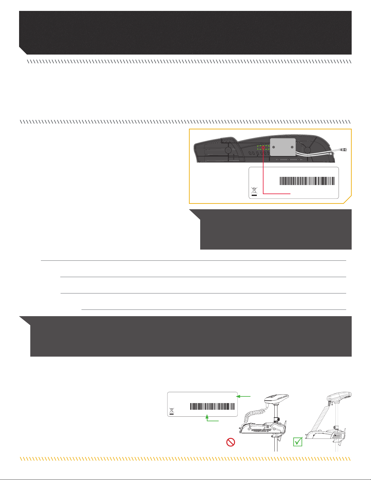
NOTICE: The serial number on your CoPilot is located
on a label inside your product package. We recommend
placing the label on the inside of the Sideplate or storing
your serial number label in a secure location.
EXAMPLE
Please thoroughly read this user manual. Follow all instructions and heed all safety and cautionary notices. Use of this product is only
permitted for persons that have read and understood these user instructions. Minors may use this accessory only under adult supervision.
THANK YOU
Thank you for choosing Minn Kota. We believe that you should spend more time fishing and less time positioning your boat. That’s why
we build the smartest, toughest, most intuitive trolling motors on the water. Every aspect of a Minn Kota trolling motor is thought out and
rethought until it’s good enough to bear our name. Countless hours of research and testing provide you the Minn Kota advantage that can
truly take you “Anywhere. Anytime.” We don’t believe in shortcuts. We are Minn Kota. And we are never done helping you catch more fish.
COMPATIBLE WITH POWERDRIVE MOTORS MANUFACTURED 2017 OR AFTER.
This remote is not compatible with PowerDrive V2 or
Legacy PowerDrive motors. Check to see that the
model name on your serial number tag includes "BT"
to ensure compatibility. Model names that do not end
in "BT" are not compatible with this remote. Motors manufactured in 2017
have a serial number that begins with the letter R. Serial Numbers starting
with a letter before R in the alphabet were manufactured prior to 2017, and
are therefore not compatible.
Model:
Serial Number:
Purchase Date:
Store Where Purchased:
REGISTRATION
Remember to keep your receipt and immediately register your
product. A registration card is included with your product or you
can complete registration on our website at minnkotamotors.com.
SERIAL NUMBER
Your Minn Kota 11-character serial number is very important. It
helps to determine the specific model and year of manufacture.
When contacting Consumer Service or registering your product,
you will need to know your product’s serial number.
We recommend that you write the serial number down so that you
have it available for future reference.
NOTICE: Do not return your Minn Kota motor to your retailer. Your retailer is not authorized to repair or replace this unit. You may obtain
service by: calling Minn Kota at (800) 227-6433; returning your motor to the Minn Kota Factory Service Center; sending or taking your
motor to any Minn Kota authorized service center. A list of authorized service centers is available on our website, at minnkotamotors.com.
Please include proof of purchase, serial number and purchase date for warranty service with any of the above options.
PowerDrive
mfg. 2017 or after
PowerDrive V2
Legacy PowerDrive
Made by Minn Kota
Johnson Outdoors
Marine Electronics, Inc.
121 Power Drive
Mankato, MN 56001 USA
Trolling Motors
Produced in 2017
70 POWERDRIVE/US2-60"_BT
MODEL 1358763
SER NO R365 MK12345

minnkotamotors.com | 3
©2019 Johnson Outdoors Marine Electronics, Inc.
Table Of CONTeNTs
WARRANTY..................................................................................................................... 4
FEATURES....................................................................................................................... 5
INSTALLATION ................................................................................................................. 6
Installing the CoPilot Receiver .................................................................................. 7
COPILOT ....................................................................................................................... 11
Controlling the Motor with CoPilot........................................................................... 11
CoPilot General Operation ...................................................................................... 11
Audio Modes ......................................................................................................... 12
Adding/Removing Remotes..................................................................................... 13
To "Learn" Remotes ............................................................................................ 13
To Erase All Remotes from the Receiver ............................................................... 13
Replacing the Battery ............................................................................................ 14
COMPLIANCE STATEMENTS.............................................................................................. 16
Environmental Compliance Statement..................................................................... 16
WEEE Directive ..................................................................................................... 16
Disposal................................................................................................................ 16
Regulatory Compliance Information......................................................................... 16
FCC Compliance.................................................................................................... 17
Industry Canada Compliance .................................................................................. 17
Environmental Ratings ........................................................................................... 17
Radio Operation .................................................................................................... 17
SERVICE & MAINTENANCE............................................................................................... 18
Troubleshooting ..................................................................................................... 18
For Further Troubleshooting and Repair ................................................................... 18
PARTS DIAGRAM & PARTS LIST ........................................................................................ 19

4 | minnkotamotors.com ©2019 Johnson Outdoors Marine Electronics, Inc.
WaRRaNTY
WARRANTY ON MINN KOTA COPILOT ACCESSORIES
Johnson Outdoors Marine Electronics, Inc. (“JOME”) extends the following limited warranty to the original retail purchaser only. Warranty coverage is
not transferable.
Minn Kota Limited One-Year Warranty on the Entire Product
JOME warrants to the original retail purchaser only that the purchaser’s new Minn Kota CoPilot Accessory will be materially free from defects in
materials and workmanship appearing within one (1) year after the date of purchase. JOME will (at its option) either repair or replace, free of charge,
any parts found by JOME to be defective during the term of this warranty. Such repair, or replacement shall be the sole and exclusive liability of JOME
and the sole and exclusive remedy of the purchaser for breach of this warranty.
Exclusions & Limitations
This limited warranty does not apply to products that have been used commercially or for rental purposes. This limited warranty does not cover normal
wear and tear, blemishes that do not affect the operation of the product, or damage caused by accidents, abuse, alteration, modification, shipping
damages, negligence of the user or misuse, improper or insufficient care or maintenance. DAMAGE CAUSED BY THE USE OF OTHER REPLACEMENT PARTS
NOT MEETING THE DESIGN SPECIFICATIONS OF THE ORIGINAL PARTS WILL NOT BE COVERED BY THIS LIMITED WARRANTY. The cost of normal maintenance
or replacement parts which are not in breach of the limited warranty are the responsibility of the purchaser. Prior to using products, the purchaser shall
determine the suitability of the products for the intended use and assumes all related risk and liability. Any assistance JOME provides to or procures
for the purchaser outside the terms, limitations or exclusions of this limited warranty will not constitute a waiver of the terms, limitations or exclusions,
nor will such assistance extend or revive the warranty. JOME will not reimburse the purchaser for any expenses incurred by the purchaser in repairing,
correcting or replacing any defective products or parts, except those incurred with JOME’s prior written permission. JOME’S AGGREGATE LIABILITY WITH
RESPECT TO COVERED PRODUCTS IS LIMITED TO AN AMOUNT EQUAL TO THE PURCHASER’S ORIGINAL PURCHASE PRICE PAID FOR SUCH PRODUCT.
Minn Kota Service Information
To obtain warranty service in the U.S., the product believed to be defective, and proof of original purchase (including the date of purchase), must be
presented to a Minn Kota Authorized Service Center or to Minn Kota’s factory service center in Mankato, MN. Any charges incurred for service calls,
transportation or shipping/freight to/from the Minn Kota Authorized Service Center or factory, labor to haul out, remove, re-install or re-rig products
removed for warranty service, or any other similar items are the sole and exclusive responsibility of the purchaser. Products purchased outside of the
U.S. must be returned prepaid with proof of purchase (including the date of purchase and serial number) to any Authorized Minn Kota Service Center in
the country of purchase. Warranty service can be arranged by contacting a Minn Kota Authorized Service Center or by contacting the factory at
1-800-227-6433 or email service@minnkotamotors.com. Products repaired or replaced will be warranted for the remainder of the original warranty
period [or for 90 days from the date of repair or replacement, whichever is longer]. For any product that is returned for warranty service that JOME finds
to be not covered by or not in breach of this limited warranty, there will be a billing for services rendered at the prevailing posted labor rate and for a
minimum of at least one hour.
NOTICE: Do not return your Minn Kota product to your retailer. Your retailer is not authorized to repair or replace products.
NOTICE: THERE ARE NO EXPRESS WARRANTIES OTHER THAN THESE LIMITED WARRANTIES. IN NO EVENT SHALL ANY IMPLIED WARRANTIES
INCLUDING ANY IMPLIED WARRANTIES OF MERCHANTABILITY OR FITNESS FOR PARTICULAR PURPOSE, EXTEND BEYOND THE DURATION OF THE
RELEVANT EXPRESS LIMITED WARRANTY. IN NO EVENT SHALL JOME BE LIABLE FOR PUNITIVE, INDIRECT, INCIDENTAL, CONSEQUENTIAL OR SPECIAL
DAMAGES. Without limiting the foregoing, JOME assumes no responsibility for loss of use of product, loss of time, inconvenience or other damage.
Some states do not allow limitations on how long an implied warranty lasts or the exclusion or limitation of incidental or consequential damages, so the
above limitations and/or exclusions may not apply to you. This warranty gives you specific legal rights and you may also have other legal rights which
vary from state to state.
minnkotamotors.com | 5
©2019 Johnson Outdoors Marine Electronics, Inc.
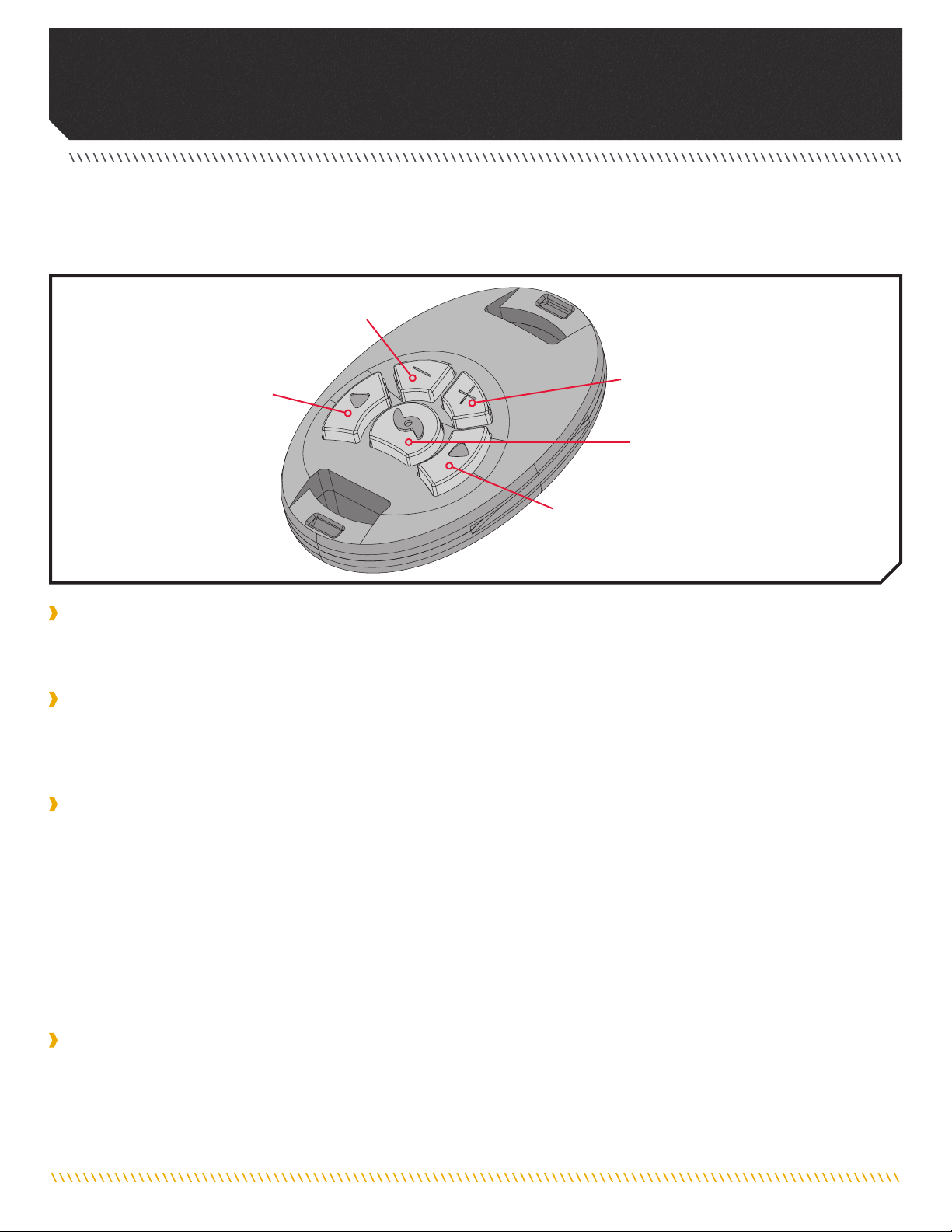
feaTURes
NOTICE: Specifications subject to change without notice. This diagram is for reference only and may differ from your
actual motor.
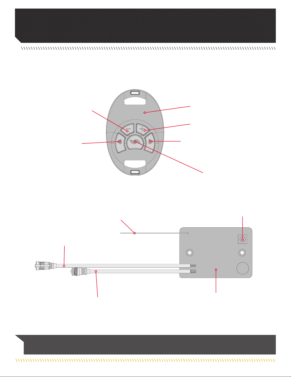
Antenna
Power Connection
Learn Button
CoPilot Receiver
Foot Pedal Connection
Steer Right
Increase Speed
CoPilot Remote
Decrease Speed
Steer Left
Prop ON/OFF
6 | minnkotamotors.com ©2019 Johnson Outdoors Marine Electronics, Inc.
INsTallaTION
INSTALLING THE COPILOT
Your new CoPilot accessory comes with everything you’ll need to directly install it on your trolling motor. These instructions are intended
to show how to install your CoPilot into the PowerDrive. Please review the parts list, mounting considerations and tools needed for
installation prior to getting started. For additional product support, please visit minnkotamotors.com.
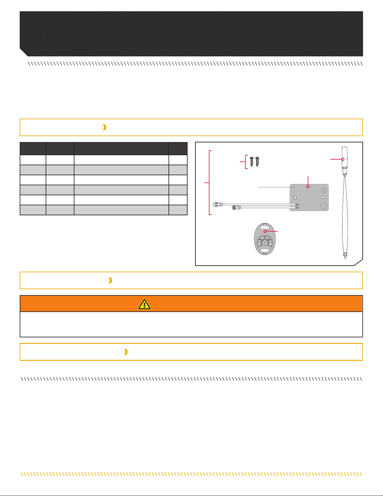
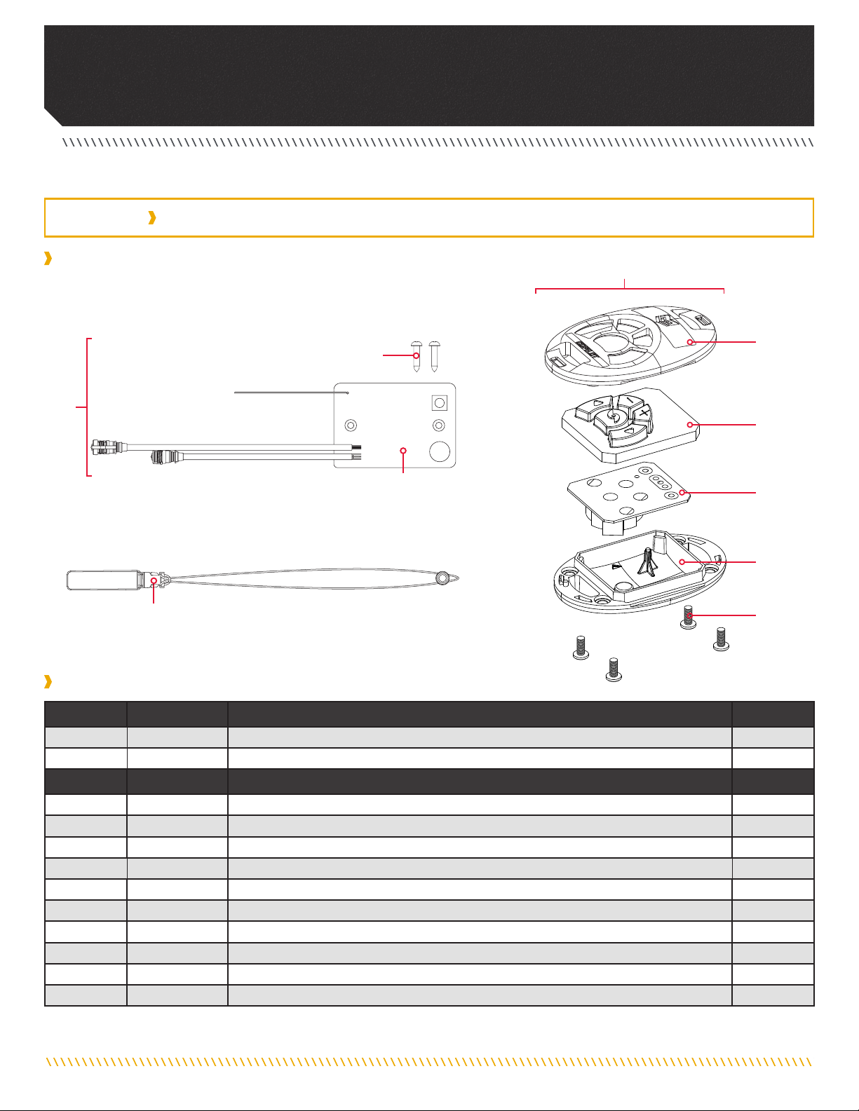
INSTALLATION PARTS LIST
• #2 Phillips Screw Driver • #3 Phillips Screw Driver
MOUNTING CONSIDERATIONS
TOOLS AND RESOURCES REQUIRED
WARNING
We recommend installing your CoPilot while the boat is on your trailer in a stable position. The motor should be secured and
disconnected from a power source before beginning installation.
1
2
B
3
✖This part is included in an assembly and cannot be ordered individually.
pNot shown on Parts Diagram.
Item /
Assembly Part # Description Qty.
A 2994112 CTRL BOARD V2 COPILOT RECEIVER 1
B 2994020 TRANSMTR, ASY, PD/AP COPLT (SUB) 1
1 2373418 SCREW-#8 X 5/8 PPHSMS S/S 2
2 2374092 CTRL BOARD V2 COPILOT RECEIVER 1
32390801 LANYARD, REMOTE 1
p2377166 MANUAL - CO-PILOT POWERDRIVE 1
A
minnkotamotors.com | 7
©2019 Johnson Outdoors Marine Electronics, Inc.
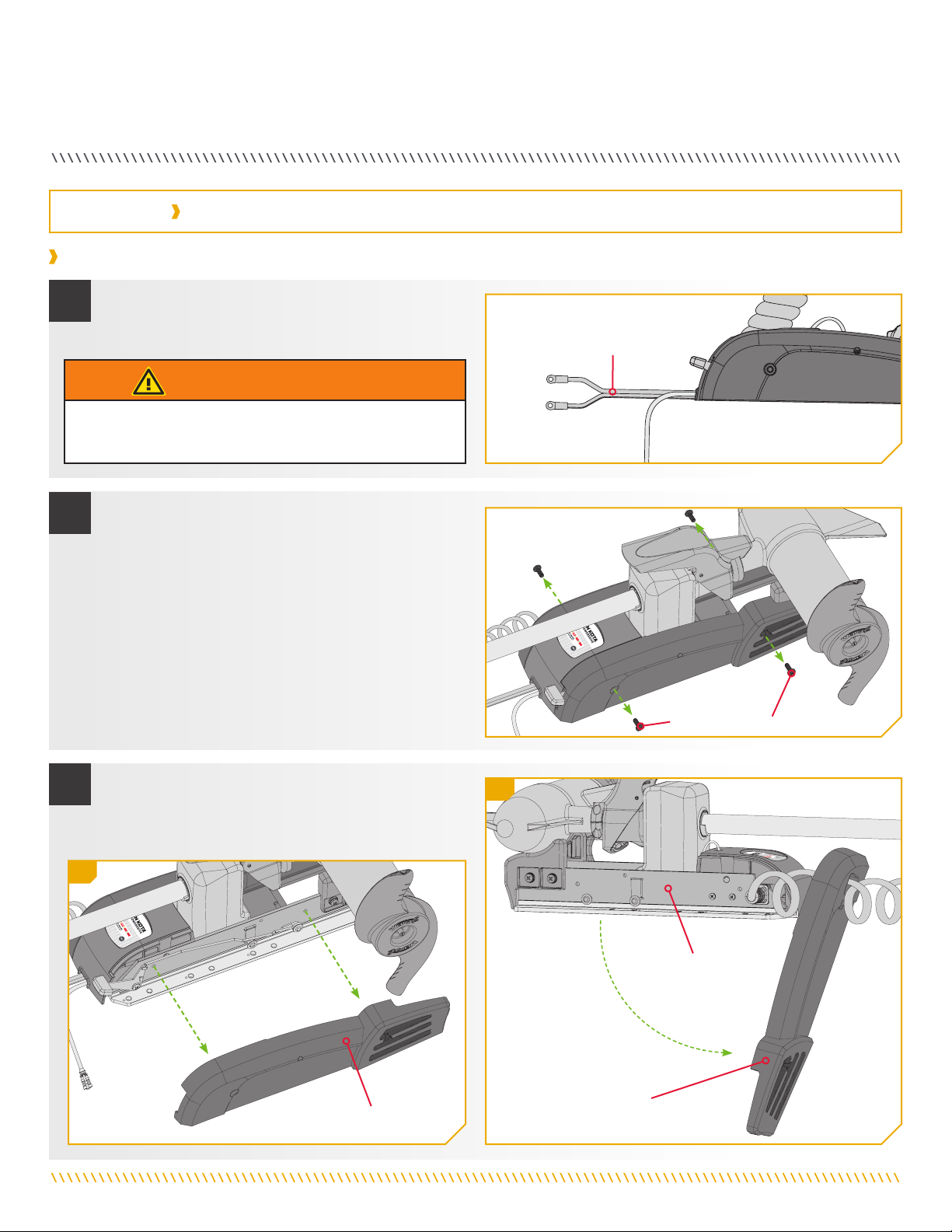
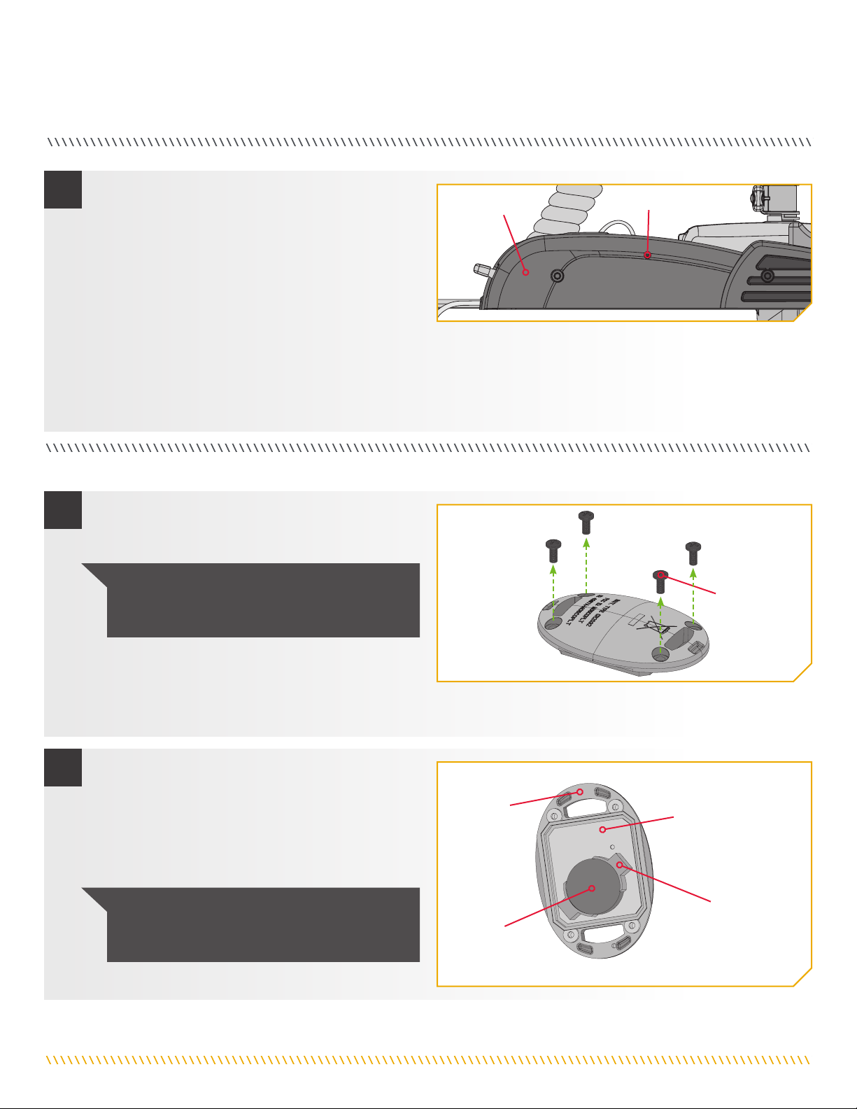
INSTALLATION
b. Using a #2 Phillips Screwdriver, remove the four
1/4-20 x 5/8’’ Screws from the Right Sideplate and
Left Sideplate of the PowerDrive mount.
a. Make sure that the Power Cables from the battery
are disconnected, or that the breaker,
if equipped, is "off." Power Cables
Sideplate Screw
c. Remove the Right Sideplate.
d. Swing the Left Sideplate out and away from the
Base Extrusion.
Right Sideplate Left Sideplate
Base Extrusion
1
2
3
WARNING
Make sure the motor is mounted on a level surface and is not
connected to a power source.
3c
3d
Installing the CoPilot Receiver
INSTALLATION

8 | minnkotamotors.com ©2019 Johnson Outdoors Marine Electronics, Inc.
INSTALLATION
g. With the Right Sideplate laying flat, and the CoPilot
receiver that was just installed facing upwards,
route the yellow wire antenna around the pegs
protruding from the Right Sideplate along the right
and bottom edge of the CoPilot Receiver. Follow the
grooves in each of the pegs.
h. Deploy the motor.
i. On the mount, lift the Center Housing to access
the components below. The Center Housing can be
released by depressing the tabs on each side that
keep it latched to the Base Extrusion.
e. Turn the Right Sideplate over and position the
CoPilot Receiver (Item #2) on the inside of the
Right Sideplate so that the receiver mounting holes
are aligned with the Sideplate Mounting Holes.
Position the wires so that they pass to the right
of the CoPilot Receiver. This should consists of a
Foot Pedal Connection, a Power Connection and an
Antenna wire.
f. Using the two #8 x 5/8’’ screws (Item #1) provided,
insert the screws through the receiver and into
the Right Sideplate. Be sure that the wires are not
pinched in the Sideplate Mounting Holes when
tightening the two screws. Do not over tighten.
ITEM(S) NEEDED
#1 x 2 #2 x 1
CoPilot Receiver
CoPilot Receiver
CoPilot Receiver
Power Connection
Screws
Power Connection
Power Connection
Center
Housing
Foot Pedal
Connection
Foot Pedal
Connection
Foot Pedal
Connection
Foot Pedal
Connection
Motor
Cable Plug
Power Cable
Sideplate
Mounting Holes
Right Sideplate
Antenna
Antenna
Right Sideplate
Right Sideplate
Right Sideplate
Left
Sideplate
Power
Connection
Base
Extrusion
5
4e
4f
5g
5i
4
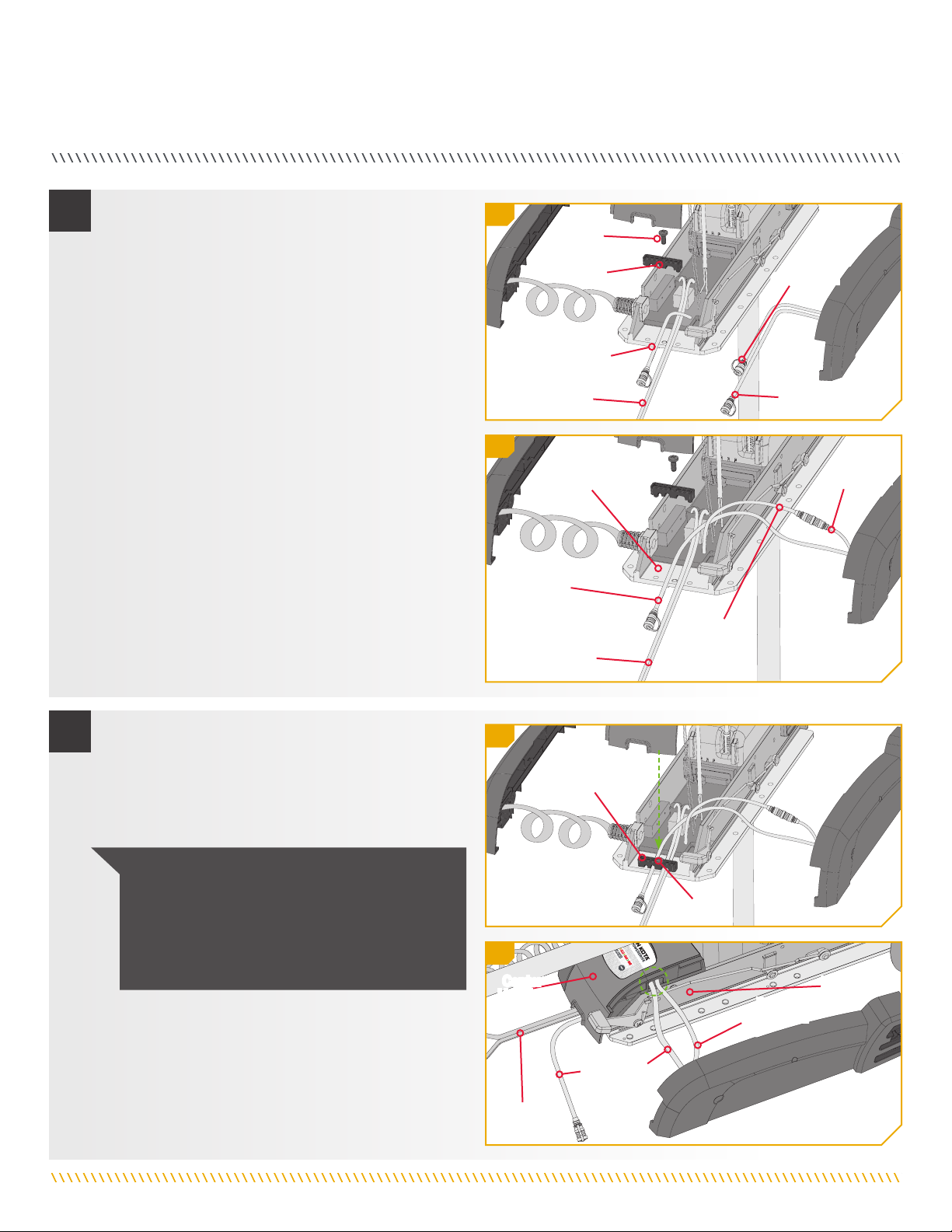
minnkotamotors.com | 9
©2019 Johnson Outdoors Marine Electronics, Inc.
INSTALLATION
j. Once lifted, using a #3 Screwdriver, remove the single
screw holding the Strain Relief Bracket in place.
k. Release the Power Cable and Motor Cable Plug from
the Strain Relief Bracket.
l. Connect the Motor Cable Plug that was previously
connected to the Foot Pedal to the CoPilot receiver
Power Connection that has the female receptacles.
m. The Foot Pedal Connection from the CoPilot
receiver can be connected to the Foot Pedal once
the installation is complete.
n. Place the Power Cable and the Foot Pedal
Connection from the CoPilot Receiver on the Base
Extrusion so that it can be captured in the Strain
Relief Bracket.
o. Using a #3 Screwdriver, replace the screw that was
holding the Strain Relief Bracket in place.
p. Be sure that the wires are routed in a way that they
can not be pinched and reseat the Center Housing
in place.
NOTICE: The wires should pass under the Center
Housing over the Base Extrusion in the notch
that creates a separation from the base and the
housing. The connection between the Motor Cable
Plug and the Power Connection should be under
the Center Housing when it is seated.
Strain Relief
Bracket
Screw
Power Cable
Power Cable
Foot Pedal
Connection
Foot Pedal
Connection
Motor Cable Plug
Motor
Cable Plug
Power
Connection
Power
Connection
Base Extrusion
Base
Extrusion
Strain Relief
Bracket
Screw
Power
Connection
Foot Pedal
Connection
Power
Cable
Center
Housing
6j
6l
7o
7p
6
7
10 | minnkotamotors.com ©2019 Johnson Outdoors Marine Electronics, Inc.
INSTALLATION
q. Once the wires are in place and the Center Housing
is seated, stow the motor to replace the Left
Sideplate
r. Replace the Right Sideplate.
Sideplate Screw
s. Using a #2 Phillips Screwdriver, replace the four
1/4-20 x 5/8’’ Screws from the Right Sideplate and
Left Sideplate of the PowerDrive mount.
Right Sideplate
Left Sideplate
Base Extrusion
8r
8
9
8q
minnkotamotors.com | 11
©2019 Johnson Outdoors Marine Electronics, Inc.
COPIlOT
Steer Right
Increase Speed
Decrease Speed
Steer Left
Prop ON/OFF
Prop ON/OFF
This button is located in the middle of the remote. It turns the propeller on or off. Press the button once to turn the propeller ON; press
button a second time to turn it OFF. The button does not need to be held down.
Steer Left & Steer Right
These buttons are located to the right and left of the Prop ON/OFF button and have an arrow symbol. They cause the motor to turn in
the desired direction as long as the button is held down. If the Steer Right or Steer Left button is held for more than seven seconds, the
steering will automatically stop until the button is pressed again.
Increase Speed & Decrease Speed
The Increase Speed and Decrease Speed buttons are located on the top of the remote and are identified with a positive and negative
symbol. Pressing and releasing these buttons causes the speed to increase or decrease by increments of 1. The speed is adjustable
from level 0-10. At level 0, the prop will not turn.
In audio mode 2, an audible beep is heard for each increment when changing speed. Attempting to go higher than speed 10 or lower
than speed 0 will result in the speed not changing and no beep will be heard. See the Audio Mode section for more information.
If the receiver senses no foot pedal or remote operation for 1 hour, the remote speed setting is automatically set to zero. This helps
prevent unintentional activation of the propeller if the prop on/off remote button is inadvertently pressed.
COPILOT GENERAL OPERATION
Operating with the Remote and Foot Pedal
• When the Momentary/Constant Switch on the Foot Pedal is in the CON position or when the Momentary Button is held, the
receiver WILL NOT RESPOND to any remote commands. When remote commands are received, the receiver will emit an audible
chirp. This will indicate that the remote is functioning properly, but the Foot Pedal is active and is overriding the remote.
CONTROLLING THE MOTOR WITH COPILOT
Review the complete CoPilot section of this manual to become familiar with this feature. For more information on CoPilot or for
additional product support, please visit minnkotamotors.com.

12 | minnkotamotors.com ©2019 Johnson Outdoors Marine Electronics, Inc.
COPILOT
• When the Momentary/Constant Switch is in the MOM position, the operator may begin using the remote at any time.
• As soon as any remote button is pressed, the initial speed setting will be set to approximately the same value as the Speed Control
value on the Foot Pedal. The prop will not automatically turn on until the Prop ON/OFF button on the remote is pressed.
• Pressing the Momentary Button on the Foot Pedal or adjusting the Speed Control dial will override the remote and receiver
function. Control of the motor will automatically go to the Foot Pedal. The prop speed will also revert to the current value of the
Speed Control dial on the Foot Pedal.
Operating without the Foot Pedal
• If the foot pedal is not being used, the CoPilot receiver will always react to any commands from the CoPilot remote.
AUDIO MODES
There are three receiver Audio Modes available. The unit is factory set to Audio Mode 2. To switch from one audio mode to another,
simultaneously press and hold the increase and decrease speed buttons for one second. The receiver will respond with
1, 2 or 3 audible beeps indicating the corresponding receiver audio mode change.
Audio Pattern What Condition Causes Audio Pattern Audio Mode
1 Beep Pressing the Increase Speed or Decrease Speed button Modes 2 and 3
1 Beep Pressing the Prop ON/OFF button to turn the Prop on Modes 2 and 3
2 Beeps Pressing the Prop ON/OFF button to turn the Prop off Modes 2 and 3
Single tick every 1.5 seconds When the Prop is active including when Speed Control dial is set to 0 Mode 3
1 Beep Switching to audio Mode 1 All
2 Beeps Switching to audio Mode 2 All
3 Beeps Switching to audio Mode 3 All
1 Chirp Every time the receiver is powered up and there is at least one remote learned All
2 second long Beep Every time the receiver is powered up and there are no remotes learned All
5 Beeps Speed Control dial on Foot Pedal (if applicable) is moved after speed has been adjusted with remote All
Steady Tone Heard while holding down the Learn button on the receiver All
4 Beeps Heard after a remote button is pressed while the receiver learns it. All
Ten second warbling sound that
transitions into a steady tone Heard during the process used to clear all stored remote. after the learn switch is released, a 2 second long
beep will be heard All
1 long Beep, 2 short Beeps, pause
(repeat) Powered up with Momentary/Constant Switch in the CON position (or the Momentary Button held) when the
Foot Pedal (if applicable) is moved to momentary, the power up audio will be heard All
NOTICE: When the Foot Pedal (if applicable) is operating the motor and the propeller is on, the prop on indicator tick will be
heard if the receiver is set to Audio Mode 3.
Audio Mode Function
Mode 1 All of the normal audible sounds mentioned in this owners manual, but no audible beeps for speed increase/ decrease or prop on/off.
Mode 2 Same as audio mode 1 plus an audible beep for speed increase / decrease and prop on/off.
Mode 3 Same as audio mode 2 plus the prop on audible tick every 1.5 seconds.
minnkotamotors.com | 13
©2019 Johnson Outdoors Marine Electronics, Inc.
COPILOT
ADDING/REMOVING REMOTES
The CoPilot remote came from the factory already "Learned" by the CoPilot receiver. Any additional remotes must be "Learned" by the
receiver. The receiver stores all "Learned" information even when the motor is disconnected from a power source.
Your receiver may learn up to ten remotes. Any additional remotes can be "Learned" using the following steps. This will also work to
"Learn" any remote if all remotes are erased from the receiver.
To "Learn" Remotes
To Erase All Remotes from the Receiver
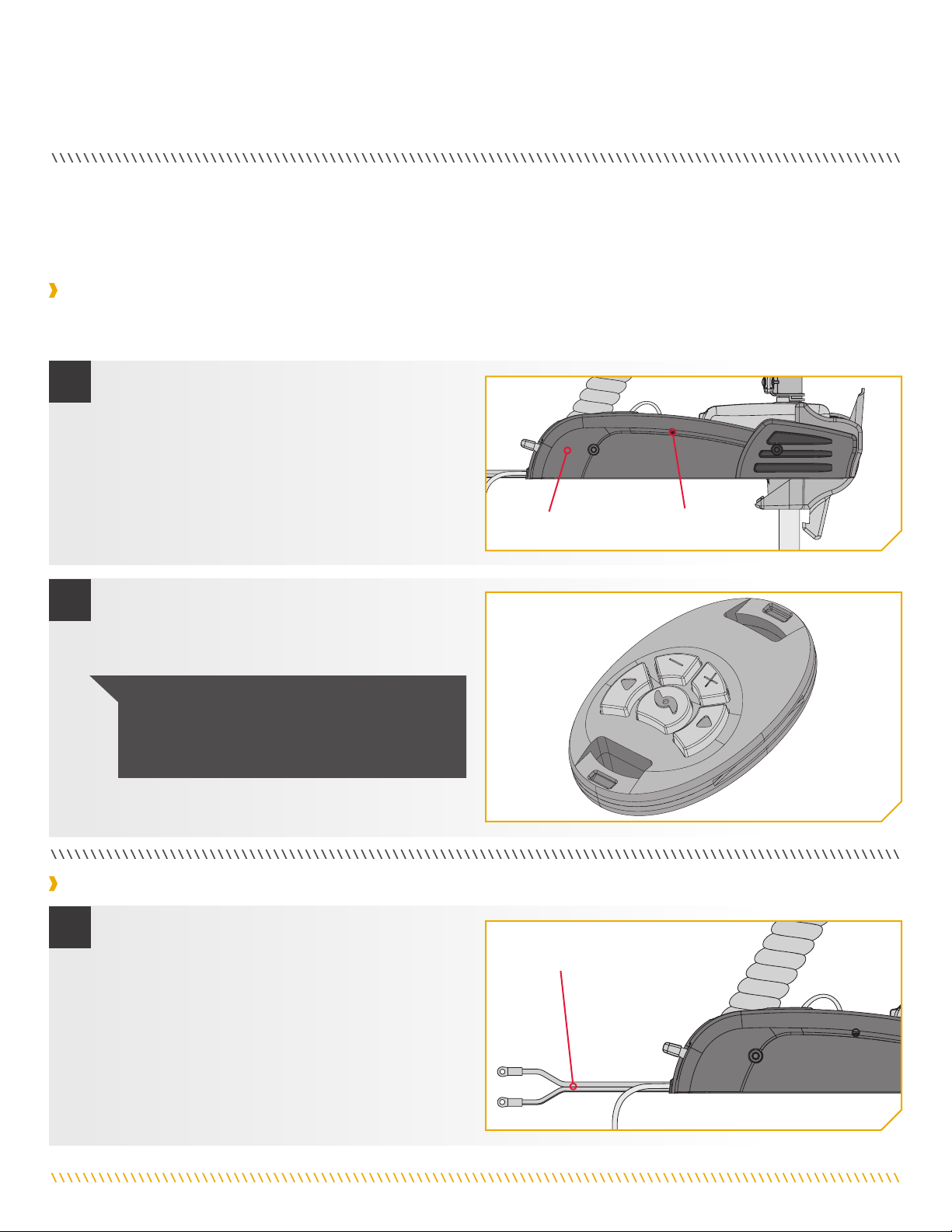
a. Using a small blunt object such as a pen or
screwdriver, press and hold the Learn Button
located on the side of the receiver.
b. The receiver will emit a continuous tone.
a. Remove power from the CoPilot receiver by
disconnecting the Power Cables, or by making sure
that the breaker, if equipped, is "off".
c. Press any button on the remote.
d. The receiver will beep 4 times confirming that it has
“Learned” the remote successfully.
NOTICE: "Learning" the same remote will not
overwrite previously “Learned” remotes. If the
receiver has “Learned” ten remotes, “Learning" an
eleventh remote will overwrite the first remote.
Power Cables
Learn Button
Right Sideplate
1
2
1
14 | minnkotamotors.com ©2019 Johnson Outdoors Marine Electronics, Inc.
COPILOT
b. Press and hold the Learn Button and power up the
CoPilot receiver by reconnecting the Power Cables, or
by making sure that the breaker, if equipped, is "on."
c. Continue to hold the Learn Button down for 10
seconds. During this time the receiver audio will
emit a warble sound, slowly transition to a constant
beep and then shut off.
d. Release the Learn Button and the receiver will
reboot. The receiver will emit a 2 second long beep
indicating memory is empty. This audio pattern
will occur each time the receiver powers up until a
remote ID number is "Learned."
Learn Button
Right Sideplate
REPLACING THE BATTERY
a. Temporarily ground yourself by touching a grounded
metal object in order to discharge any static
electricity in your body.
b. Remove the four screws on the bottom of the
remote case.
c. Separate the case halves to access the circuit board.
NOTICE: The replacement battery must be
a model CR2032 coin cell type. It is strongly
recommended that a name brand battery is used.
d. To remove the Battery, place the tip of a finger or
thumb under the exposed edge of the Battery and
pry it upwards.
e. Install the new battery with the positive (+) side
of the Battery facing up and away from the Circuit
Board. Ensure Battery is snapped securely in place.
Retaining Fingers
Circuit Board
Remote
Case Front
Screws
NOTICE: The replacement battery must be a model
CR2032 coin cell type. It is strongly recommended
that a name brand battery is used.
Battery
1
2
2
minnkotamotors.com | 15
©2019 Johnson Outdoors Marine Electronics, Inc.
COPILOT
f. Reassemble the remote. Begin by removing the
board from the front of the remote case. This is
the same board that holds the battery. Leave the
Keypad in place on the front of the remote.
g. Note that the alignment peg in the back of remote
case must line up with the corresponding alignment
hole in the circuit board. Place the board with the
battery facing down on the back of the remote case.
Alignment
Peg
Battery
Retaining
Fingers
Retaining
Fingers
Battery
Remote
Case Front
Remote
Case Back
Remote
Case Front
Remote
Case Back
h. Position the back of the remote case so that the
Alignment peg is towards the top when the remote
is laying on a flat surface. Position the front of the
remote case so the keypad and the curved buttons
are towards the bottom when the remote is laying
on a flat surface.
i. Keep the back of the Remote Case flat. Place the
front of the Remote Case, with the Keypad is place,
on the back of the Remote Case. Make sure the
Case is seated. Circuit
Board
Keypad
Alignment
Peg
Screws
j. Reinstall the four case screws and tighten them
as required.
3
4
5
3f
3g
16 | minnkotamotors.com ©2019 Johnson Outdoors Marine Electronics, Inc.
COMPlIaNCe sTaTeMeNTs
ENVIRONMENTAL COMPLIANCE STATEMENT
It is the intention of JOME to be a responsible corporate citizen, operating in compliance with known and applicable environmental
regulations, and a good neighbor in the communities where we make or sell our products.
WEEE DIRECTIVE
EU Directive 2002/96/EC “Waste of Electrical and Electronic Equipment Directive (WEEE)” impacts most distributors, sellers, and
manufacturers of consumer electronics in the European Union. The WEEE Directive requires the producer of consumer electronics to
take responsibility for the management of waste from their products to achieve environmentally responsible disposal during the product
life cycle.
WEEE compliance may not be required in your location for electrical & electronic equipment (EEE), nor may it be required for EEE
designed and intended as fixed or temporary installation in transportation vehicles such as automobiles, aircraft, and boats. In some
European Union member states, these vehicles are considered outside of the scope of the Directive, and EEE for those applications can
be considered excluded from the WEEE Directive requirement.
This symbol (WEEE wheelie bin) on product indicates the product must not be disposed of with other household
refuse. It must be disposed of and collected for recycling and recovery of waste EEE. Johnson Outdoors Inc. will mark
all EEE products in accordance with the WEEE Directive. It is our goal to comply in the collection, treatment, recovery,
and environmentally sound disposal of those products; however, these requirements do vary within European Union
member states. For more information about where you should dispose of your waste equipment for recycling and
recovery and/or your European Union member state requirements, please contact your dealer or distributor from which
your product was purchased.
DISPOSAL
Minn Kota motors are not subject to the disposal regulations EAG-VO (electric devices directive) that implements the WEEE directive.
Nevertheless never dispose of your Minn Kota motor in a garbage bin but at the proper place of collection of your local town council.
Never dispose of battery in a garbage bin. Comply with the disposal directions of the manufacturer or his representative and dispose of
them at the proper place of collection of your local town council.
REGULATORY COMPLIANCE INFORMATION
MODEL: COPILOT
• IC: 4397A-M05COPLT
• FCC ID: MO5COPLT

minnkotamotors.com | 17
©2019 Johnson Outdoors Marine Electronics, Inc.
COMPLIANCE STATEMENTS
FCC COMPLIANCE
This device complies with Part 15 of the FCC rules. Operation is subject to the following two conditions:
1. This device may not cause harmful interference.
2. This device must accept any interference that may be received, including interference that may cause undesired operation.
Changes or modifications not expressly approved by Johnson Outdoors Marine Electronics, Inc. could void the user’s authority to
operate this equipment.
INDUSTRY CANADA COMPLIANCE
This product meets the applicable Industry Canada technical specifications. Operation is subject to the following two conditions:
(1) this device may not cause interference, and (2) this device must accept any interference, including interference that may cause
undesired operation of the device.
Changes or modifications not expressly approved by Johnson Outdoors Marine Electronics, Inc. could void the user’s authority to
operate this equipment.
NOTICE: This equipment has been tested and found to comply with the limits for a Class B digital device, pursuant to part
15 of the FCC Rules. These limits are designed to provide reasonable protection against harmful interference in a residential
installation. This equipment generates, uses and can radiate radio frequency energy and, if not installed and used in accordance
with the instructions, may cause harmful interference to radio communications. However, there is no guarantee that interference
will not occur in a particular installation. If this equipment does cause harmful interference to radio or television reception, which
can be determined by turning the equipment off and on, the user is encouraged to try to correct the interference by one or more of the
following measures:
• Reorient or relocate the receiving antenna.
• Increase the separation between the equipment and receiver.
• Connect the equipment into an outlet on a circuit different from that to which the receiver is connected.
• Consult the dealer or an experienced radio/TV technician for help.
CE MASTER USER MANUAL (FOR CE CERTIFIED MODELS)
Ambient operating temperature range: -10C to 50C
Ambient operating humidity range: 5% to 95%
Maximum operating altitude: 10,000 feet
• Frequency band: 433.92 MHz
• Maximum RF power transmitted: +7 dBm
ENVIRONMENTAL RATINGS
RADIO OPERATION

18 | minnkotamotors.com ©2019 Johnson Outdoors Marine Electronics, Inc.
seRVICe & MaINTeNaNCe
TROUBLESHOOTING THE COPILOT
Cause Effect Solution
Remote is not transmitting.
The battery is discharged.Replace battery.
Receiver may not have "learned" the remote. Remote needs to be learned. See the Adding/Removing Remotes
section of this manual to learn the remote.
With the foot pedal (if applicable) connected, the MOM-
CON switch is in the CON position. An audio response will
be heard if a button is pressed with the foot pedal in the
CON position.
The foot pedal (if applicable) switch must be placed in Momentary
Mode (MOM). The receiver will not accept any commands from the
remote with the switch in the Constant Mode (CON) position.
If remote has been taken apart, the keypad and top case
may have been installed backwards. Take remote apart. See the Replacing the Battery section of this
manual and reinstall case halves with the proper orientation.
When receiver is powered up, it sounds a
beep pattern (1 long beep, 2 short beeps,
pause, repeat).
The foot pedal (if applicable) Momentary/Constant Switch
is in the CON position.
The foot pedal (if applicable) switch must be placed in the MOM
position. The beeping sound will continue until the switch is placed in
the MOM position.
The prop is not turning but the Prop ON
audio pattern is still going.
Prop Speed is set at "0". Increase the Prop Speed above "0"
The Prop ON audio pattern occurs only in Audio Mode 3 Switch Audio Mode to either Audio 1 or 2. See the Audio Modes section
of this manual.
FOR FURTHER TROUBLESHOOTING AND REPAIR
We offer several options to help you troubleshoot and/or repair your product. Please read through the options listed below.
Buy Parts Online
You can buy parts on-line directly from our website at minnkotamotors.com. Orders confirmed by 12 noon central time will ship
same day if in stock. Orders after 12 noon central time will ship the next business day if in stock.
Frequently Asked Questions
We have FAQs available on our website to help answer all of your Minn Kota questions. Visit minnkotamotors.com and click on
“Frequently Asked Questions” to find an answer to your question.
Call Us (for U.S. and Canada)
Our consumer service representatives are available Monday – Friday between 7:00 a.m. – 4:30 p.m. CST at 800-227-6433. If you
are calling to order parts, please have the 11-character serial number from your product, specific part numbers, and credit card
information available. This will help expedite your call and allow us to provide you with the best consumer service possible. You can
reference the parts list located in your manual to identify the specific part numbers.
Email Us
You can email our consumer service department with questions regarding your Minn Kota products.
To email your question, visit minnkotamotors.com and click on “Support”.
Authorized Service Centers
Minn Kota has over 800 authorized service centers in the United States and Canada where you
can purchase parts or get your products repaired. Please visit our Authorized Service Center page
on our website to locate a service center in your area.
Scan to visit Minn
Kota service online.
minnkotamotors.com | 19
©2019 Johnson Outdoors Marine Electronics, Inc.
PaRTs DIaGRaM & PaRTs lIsT
COPILOT ACCESSORY
B
6
8
14
10
12
2
4
A
CoPilot Parts Diagram
POWERDRIVE
16
Assembly Part # Description Quantity
A2994112 CTRL BOARD V2 COPILOT Receiver 1
B2994020 TRANSMTR, ASY, PD/AP COPLT 1
Item Part # Description Quantity
2 2373418 SCREW-#8 X 5/8 PPHSMS S/S 2
4 2374092 CTRL BOARD V2 COPILOT RECEIVER 1
6 2372503 CASE, COVER, TRANSMITTER ASY 1
82375110 KEYPAD, TRANSMITTER ASSY 1
10 2372505 CASE, BOTTOM, TRANSMITTER ASSY 1
12 2373440 SCREW-#4-24 X 1/4 PHCR SS TY B 4
14 ✖PCB ASY, CO-PILOT TRANSMITTER 1
16 2390801 LANYARD, REMOTE 1
p2005621 DECAL - CE/RCM/WEE CMPLNC.MARK 1
p2377166 MANUAL-CO-PILOT V3 1
CoPilot Parts List
✖This part is included in an assembly and cannot be ordered individually.
pNot shown on Parts Diagram.

Minn Kota Consumer & Technical Service
Johnson Outdoors Marine Electronics, Inc.
PO Box 8129
Mankato, MN 56001
121 Power Drive
Mankato, MN 56001
Phone (800) 227-6433
Fax (800) 527-4464
minnkotamotors.com ©2019 Johnson Outdoors Marine Electronics, Inc.
All rights reserved.
Part #2377166 Rev D 09/19ECN 40105
• 60-Amp Circuit Breaker
• Mounting Brackets
• Stabilizer Kits
• Extension Handles
• Battery Connectors
• Battery Boxes
• Quick Connect Plugs
TALON SHALLOW WATER ANCHOR
Introducing the all-new, sleek redesigned Talon. Talon is the only shallow water anchor with up to 15’ of anchoring
depth, multiple anchoring modes, and control from the bow, transom, console, remote or mobile device.
MINN KOTA ACCESSORIES
We offer a wide variety of trolling motor accessories, including:
UP TO 15’ DEEP
Control more water and catch
more fish with the first 15’
shallow water anchor.
BUILT-IN
WORK LIGHT
Lets you tie lines and work from
the transom any time of day —
or night. Includes both white
and blue LED lights with three
brightness settings.
MORE CONTROL
OPTIONS
• Control Panel
• Wireless Remote
• Mobile App
• Wireless Foot Switch
• Humminbird®Connectivity
• i-Pilot®&
i-Pilot LinkTM Remote
BLUETOOTH®
CONNECTIVITY
Lets you control Talon from your
mobile device and easily update
it. Also opens up communication
to other control options.
ReCOMMeNDeD aCCessORIes
ON-BOARD & PORTABLE BATTERY CHARGERS
Stop buying new batteries and start taking care of the ones you’ve got. Many chargers can actually damage your
battery over time – creating shorter run times and shorter overall life. Digitally controlled Minn Kota chargers are
designed to provide the fastest charge that protect and extend battery life.
MK210 D M K110 P DMK212PC
Other manuals for CoPilot
1
Table of contents
Languages:
Other MINN KOTA Marine Equipment manuals


