Katadyn PowerSurvivor 40 User manual

INSTALLATION INSTRUCTIONS
REPAIR SEAL KIT
PowerSurvivor 40
Print No.: 8012646/1 Katadyn Desalination LLC Katadyn Products Inc.
2220 S.McDowell Blvd Pfäffikerstrasse 37
Petaluma, CA 94541 U.S.A 8310 Kemptthal Switzerland
Phone: +14155262780 Tel +41 44 839 21 11 Fax +41 44 830 21 99
[email protected] [email protected] www.katadyngroup.ch
PURPOSE OF THE KIT
The Repair Seal Kit should be installed after 1000 hours of operation. It should be installed regardless of whether
there is leakage or a reduction of fresh water. Learning to perform this procedure will ensure optimal performance
of your watermaker.
INSTALLATION INSTRUCTIONS
NOTE: See Fig. A-2 for an overall view of the Pump Assembly.
Over time, the dynamic Seals and O-rings in the PowerSurvivor 40E will wear. The Repair Seal Kit contains the
major seals and O-rings that should be replaced to improve operating efficiency. It also contains new check valve
poppets, springs, and drive oil which should be replaced simultaneously. This Repair Seal Kit should be installed
after roughly 1000 hours of operation. It should be installed regardless of whether there is leakage or a reduction
of fresh water. Learning to perform this procedure will help users ensure optimal performance.
Before beginning the Repair Seal Kit procedure, note the following precaution:
1. Keep the work area clean and clear of dirt, hair, and other contaminants.
2. Avoid scratching Pump Components when removing or replacing O-rings.
3. All seals and O-rings should be lubricated with silicone grease. Never use petroleum-based lubricants
as a substitute.
4. When installing O-rings, do not roll or twist them.
NOTE: Average time to replace all seals is 1 hour. If you are performing this maintenance for the first time, expect
it to take 3 hours.
CONTENT OF THE KIT
•Silicon lubricant
•Locktite
•Hose barbLubricating oil
•Small parts see Figs.1a and 1b
TOOLS REQUIRED
•Piston Seal Installation Tool –supplied with kit
•1/2-inch open-end wrench
•1/4-inch Allen wrench
•5/32-inch Allen wrench
•5/8-inch open-end wrench
•small flat-bladed screwdriver
•needle-nosed pliers
•medium channel lock pliers
•small scissors

DISASSEMBLY
1. Before beginning disassembly, run the watermaker and stop it when the piston shaft is at its farthest point of
travel away from the pump (i.e., toward the drive assembly). This provides enough room for sliding the
rubber boot toward the pump in Step
3.
2. Disconnect the pump from the drive
assembly by first removing the two hex
nuts and 5" sockethead capscrews
from the check valve plate, using the
1/2" open-end wrench and 1/4"
Allen wrench. Also remove the two hex
nuts securing the pump back plate to
the drive assembly. (See Figure R-1).
3. Slide the black rubber boot on the
piston shaft toward the pump to expose
the drive shaft coupling pin. Use a
small Allen wrench or similar tool to
push the coupling pin out of the drive
shaft (see Figure 8). Be aware that the coupling pin fits loosely in the drive shaft and may fall out when the
rubber boot is removed. Be careful not to lose it. Separate the drive assembly from the pump and set the
drive assembly aside.
4. Remove the two 3" socket-head cap
screws using a 1/4" Allen wrench.
Separate the pump back plate and
piston assembly from the pump body
(see Figure R-2).
5. If the piston assembly remained with
the pump back plate when it was
removed, pull the piston out of the back
plate, and set it aside. If the piston
stayed in the main pump body, pull it
out of the cylinder. If the piston assem-
bly is difficult to remove from the pump
body, insert a small Allen wrench or
Phillips screwdriver through the cou-
pling pin hole. This will provide a “t-
handle” with a better grip for
extracting the piston assembly. Be
aware not to damage the surface of
the piston shaft.
6. Remove the large O-ring (8012588) from its groove in the side of
the pump back plate that faces the pump body. Remove the wiper
block and spacer (if present) from the pump back plate. Use needle-
nosed pliers to pull the old wiper block seal out of the wiper block.
See Figure R-3. (Note: This seal is usually damaged during removal.
Be sure you have a replacement on hand before removing it.)

7. From the side of the pump back plate that contained the large O-ring, insert a round drift of slightly smaller
diameter than the hole for the piston shaft. (Note: a small socket on an extension or a wooden dowel makes
a suitable drift). Tap the drift with a mallet to drive the two backup washers, two piston shaft seals and the
piston shaft bushing out of the pump back body. See Figure R-4.
8. Remove the remaining two 3/4" socket head cap screws from the check valve plate using a 1/4" Allen
wrench. Separate the check valve plate from the pump body.
If it is difficult to remove, try rotating the check valve plate 90°.
This provides a better grip for pulling the check valve plate
from the pump body.
9. After the check valve plate has been separated from the pump
body, the membrane tube plug will remain in either the check
valve plate or the pump end of the membrane housing. Use
one of the following procedures to remove it:
A. If the membrane tube plug remains in the mem-
brane housing, insert a hard, thin edge (e.g., a dull
pocketknife) between the tube plug and the fiberglass
moulding of the membrane housing. Work the blade
sideways to pry the tube plug out slightly, until there is enough of a gap between the tube plug body
and the membrane housing to insert a flat blade screwdriver. Then use two screwdrivers on opposite
sides of the tube plug to carefully work it out of the membrane housing. Avoid gouging or damaging
the membrane housing or the tube plug.
B. If the membrane tube plug remains in the check valve plate, use a thin edge and/or flat blade
screwdrivers, on opposite sides of the membrane tube plug, to carefully pry the plug out of the check
valve plate. Avoid damaging the membrane tube plug.
10. Disassemble the valves in the check valve plate
(see Figure R-5.) Use a 5/8" open end wrench
to unscrew the intake valve seat. Remove the
intake poppet valve and its spring. If necessary,
use needle-nosed pliers to remove the poppet
valve retainer. Then use the pliers to lift out the
reject poppet valve and its seat. Grip the x-
shaped ribs of the reject poppet valve and pull
straight up. The seat will be pulled out along
with the valve. After the reject poppet valve and
its seat have been removed, retrieve the reject
poppet valve spring from the bottom of the
check valve plate cavity.
This completes the disassembly of all user-
serviceable parts of the Katadyn PowerSurvivor
40E Watermaker.

REASSEMBLY:
Before you begin reassembly of the watermaker, clean all parts using clean, lint-free rags. At this time, all parts
should be carefully inspected for wear or damage. Use a 10x magnifier or loupe to examine the seals, O-rings,
and other small parts. Stubborn rust stains and other deposits on metal parts can be cleaned with a soft-metal
wire brush (e.g., stainless steel or brass). Do not use polishes, cleaning compounds containing abrasive materials,
or regular steel wire brushes. During reassembly, refer to Figures A-3 and A-4 in the Appendix for full-size
drawings and identification of the components included in the Repair Seal Kit.
In the following procedure for reassembling the watermaker, it is assumed that all parts have been cleaned and
that all O-rings, seals, and mating surfaces have been lightly lubricated with non-petroleum silicon grease
(supplied with the Repair Seal Kit). References to the Repair Seal Kit will be abbreviated to “RSK.”
Warning: Use only non-petroleum silicon grease to lubricate your watermaker. Lubricants with a petroleum
base will damage several watermaker components, including the reverse osmosis membrane. Be especially
cautious of lubricants that “contain” Teflon, silicon, etc.—such products could also contain petroleum-based
components. An ample supply of silicon grease is included with each RSK.
1. Make a note of the correct orientation of the old cup ring and PIP seal and then remove them from the
piston assembly. Since these components are made of rather stiff rubber, it is usually easier to cut them
off. Use a small screwdriver to wedge under the cup seal and pry it up. While holding it up, cut it with a
small pair of scissors. Repeat this process for the PIP ring.
•Reinstall the piston: If you want to replace the O-rings on the
piston, refer to the figure below
oInstall washer with chamfer on washer facing ½” dia
of plunger rod and a new O-ring onto the plunger
rod, if you have an old-style piston, you only have to
install a new O-ring (8013008) into the plunger rod
without a washer.
Slide piston onto the threaded end of the plunger rod, and secure
with the washer and nut as well as one drop of Locktite.2.Refer to
Figure R-6 during the following procedure. Place the piston
assembly on a flat, stable surface with the shaft pointing up. Slide
the installation tool (provided in the RSK)
over the piston shaft with the wide end
down. Lubricate the new PIP ring, cup seal
and the installation tool with silicon grease.
With the grooved side facing up, slide the
PIP ring down the installation tool and onto
the piston. Repeat this process for the cup
seal. Note that the grooved side of the cup
seal should be facing down, i.e., the
grooved sides of the PIP ring and the cup
seal should be facing each other. When
finished with the installation, remove the
installation tool from the piston shaft.
Note: This is a very tight fit by design and
will require a fair amount of force to push the PIP ring down the installation tool. You may use an object to
help push the pip ring evenly down the tool. Please make sure not to damage the PIP ring.

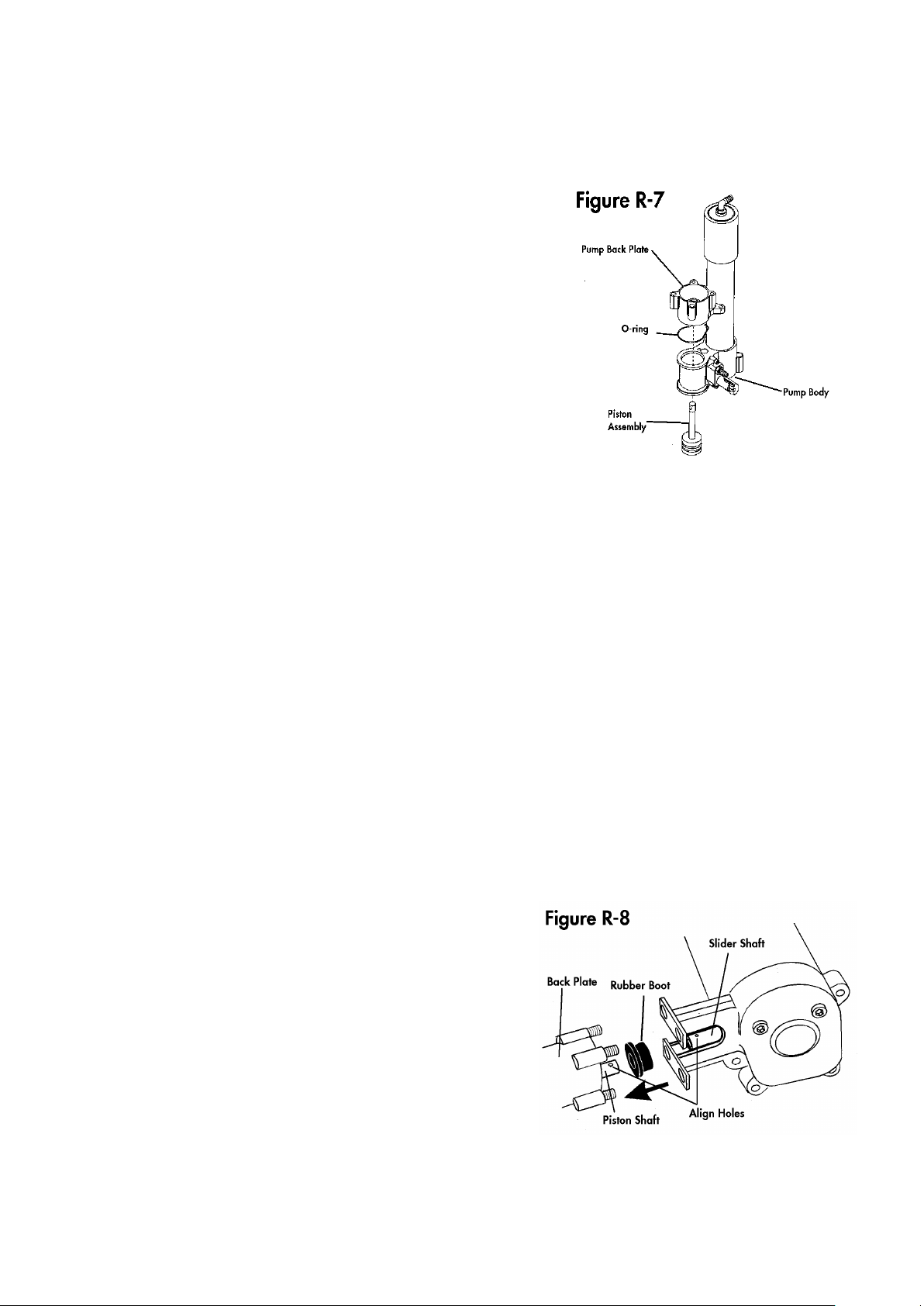
3. Lightly lubricate the cylinder in the pump body with silicon grease. Slide the finished piston assembly, shaft
first, into the pump body from the side of the pump body that faces the check valve plate. Install the large O-
ring (8012588) into its groove in the pump back plate and lower the pump back plate over the piston shaft.
The side of the back plate with the large O-ring should be facing the pump body. See Figure
R-7.
4. Refer to Figure R-4. Slide one of the white backup washers over the
piston shaft and press it into its bore in the pump back plate. Next,
slide one of the two black rubber piston shaft seals over the piston
shaft and work it into the bore on top of the backup washer. Note
that the shaft seals are flared out on one side. It is important that the
flared (wider) side should be down, facing the shaft bore. Install the
second piston shaft seal in the same way. It too should be installed
with its flared side facing down. Next, install the second white
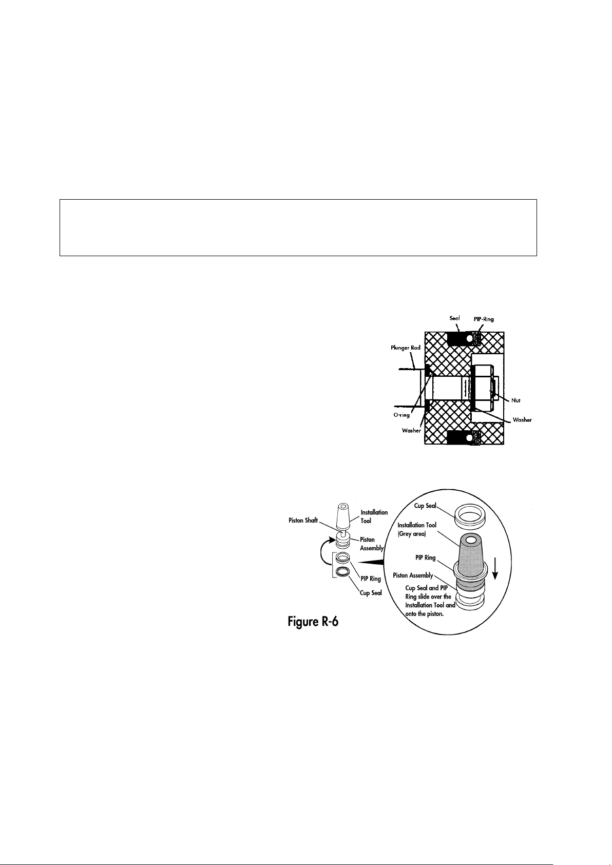
backup washer and, finally, the white bushing. Slide the installation
tool (used in Step 2 above) over the piston shaft with the narrow
end facing the white bushing. Use the installation tool to press the
shaft washers, seals and bushing all the way into the bore. When
finished, the outside end of the bushing should be flush with the bore
opening.
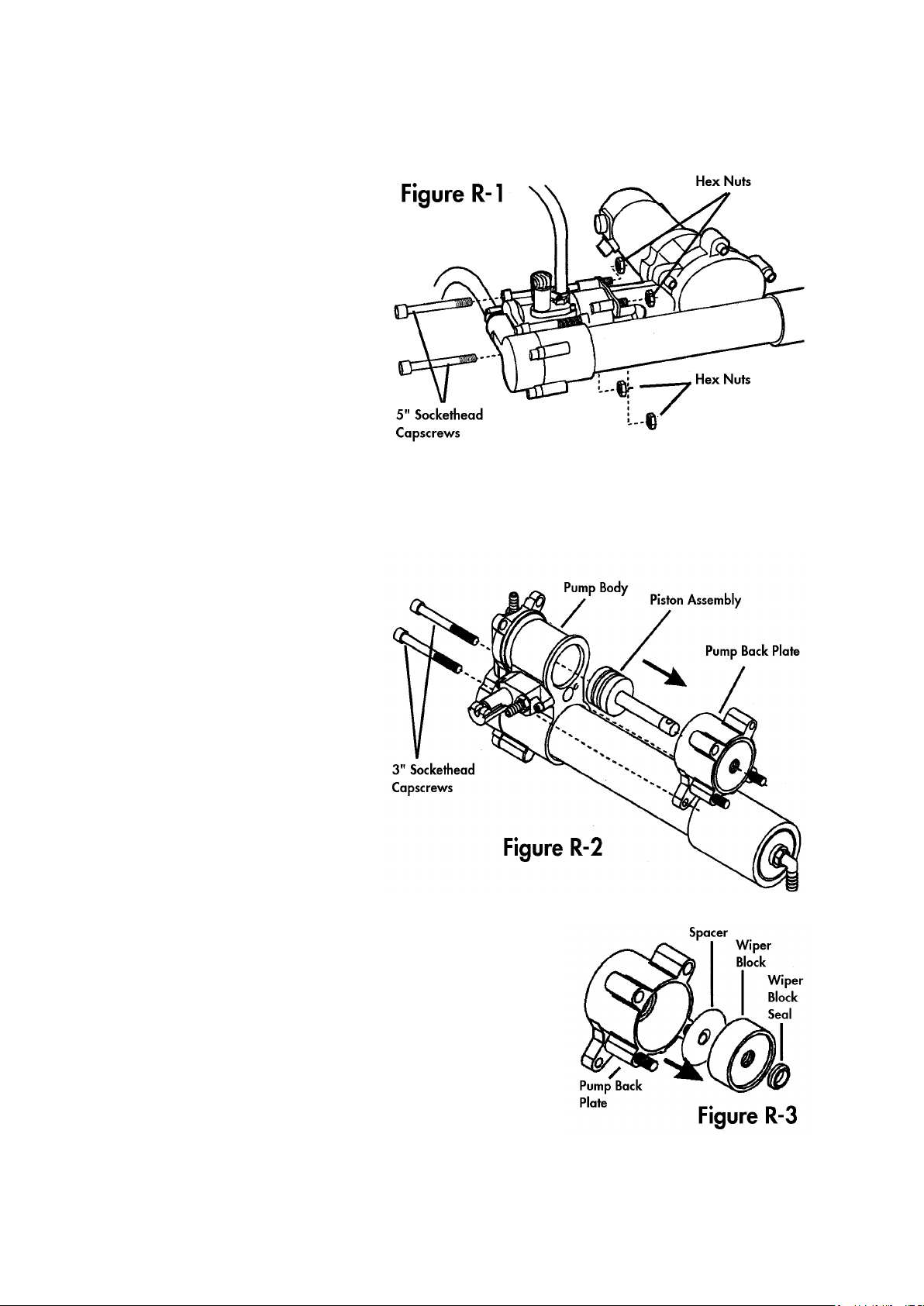
5. Install a new wiper block seal (8012776) into the wiper block. The
seal must be pressed into a groove inside the bore in the middle of the wiper block with the narrower side
of the seal facing outwards. Form the seal into an oval shape by squeezing it between your fingers and press
one side of the seal into the groove in the wiper block. Once an edge of the seal is started into the groove,
carefully work the rest of the seal into place. After the seal has been installed, slide the spacer (if present)
and wiper block onto the piston shaft. The side of the wiper block from which the seal was installed should
be facing outward. Refer to Figure R-3.
6. Prepare the check valve plate for reassembly by installing the new poppet valves. Note that both the intake
and reject poppet valves and valve springs are identical. Refer to Figure R-5 during the following procedure:
A. Lower a new poppet valve spring (8013120) into the bottom of the bore in the check valve plate. Use
your little finger or the eraser end of a pencil to press it into its seat. It is designed to be a light press fit
and, when installed correctly, it should stay vertical in place during the next step.
B. Use needle-nosed pliers to carefully lower one of the new poppet valves (8012978) into the bore. The
poppet valve should rest on top of the spring with the poppet’s cross side facing up.
C. Lower the new reject valve seat (8012977) into the bore and use a finger to press it down as far as it
will go. Note that the hole in the middle of the valve seat has a beveled edge on one side. The side with
the beveled edge must face downward; i.e., it must face the poppet valve. When properly installed, the
valve seat should fit neatly over the poppet valve. Test the poppet valve by pressing it with the eraser
end of a pencil. It should move up and down slightly and seat squarely in the valve seat.
D. Locate the small depression in the center of one end of the poppet valve retainer and press the second
valve spring (8013120) into the depression. It was
designed as a light press fit and should stay in place after
being installed. Then lower the poppet valve retainer into
the bore in the check valve plate with the spring facing
upward.
E. Lower the second poppet valve into the bore in the check
valve plate and rest it carefully on top of the valve spring.
F. Remove the old o-ring (8013015) from the intake valve seat
and replace it with the new one from the RSK. Carefully
screw the intake valve seat into the check valve plate and
tighten with a 5/8" open end wrench. Use the eraser end
of a pencil or a small allen wrench to test the operation of
the intake poppet valve. The poppet valve should move down slightly and then spring back up against
its seat. Re-install the hose barb if intact, or replace it with a hose barb, delivered with the kit.

7. Replace the two large O-rings (8012947) and the two smaller O-rings (8013006) on the
membrane tube plug with new O-rings from the RSK. Insert the small end of the membrane tube plug
into the exposed hole in the membrane element (which should have been left installed in the membrane
housing) and press the tube plug into the membrane housing as far as it will go. The ridge on the outside
of the tube plug should be flush against the end of the membrane housing.
8. Press the piston as far as it will go toward the pump back plate. Install a new O-ring (8012588) into
its groove in the check valve plate.
9. Press the check valve plate over the exposed end of the membrane tube plug. If necessary, rotate the
check valve plate to align it accurately with the pump body and install the 3/4" and the 3" socket
head cap screws. Check that the two large O-rings (8012588) in the check valve plate and the pump
back plate are still seated in their grooves and then tighten the four cap screws evenly with a 1/4"
Allen wrench.
10. Slide the two 5" socket head cap screws through the holes in the check valve plate and the back
plate. Slide the rubber boot onto the piston shaft. See Figure R-8.
11. Insert a small screwdriver or an Allen wrench through the hole in the piston shaft and rotate the shaft
to align its hole with the hole in the slider shaft of the drive assembly. When they are aligned, slide
the holes in the drive assembly bracket over the studs projecting from the pump back plate. Insert
the coupling pin through the aligned holes in the slider shaft and piston shaft. Push the rubber boot
over the coupling pin to hold it in place.
12. Install the four hex nuts on the
studs projecting from the pump
back plate through the drive
assembly bracket and tighten
evenly with a 1/2" open-end
wrench and 1/4" Allen wrench.
Do not overtighten these
fasteners!
13. To replace the O-rings beneath
the cleaning valve assembly,
refer to Figure R-9. Unscrew the
two socket head cap screws using
a 5/32" Allen wrench and
remove the assembly from the
pump body. Remove old O-rings
(8012594) and (8012697) and
replace them with new O-rings
from the RSK. Replace the
cleaning valve assembly on the pump body and install the two cap screws. This completes the
procedure for reassembly of the watermaker. When operation is commenced again, carefully inspect
the watermaker for proper operation and any leaks or other signs of incorrect assembly.

MEMBRANE REPLACEMENT
NOTE: Run the system for a short time with the cleaning valve open to relieve internal pressure. This will
ensure that the spring clamp can be easily removed in step 2 below.
1. If the End Cap has the freshwater
product hose attached, remove
the hose (see Figure 1).
2. Use the flat blade screwdriver to
lift the end of the Spiral Ring on
the End Cap. Pull the Spiral Ring
off (see Figure 2).
3. Remove the end cap by pulling
gently on the hose barb and end
cap taking care not to destroy the
hose barb.
NOTE: End caps may not come off
easily. Grasp the hose barb gently
and pull the end cap off. It may be
necessary to wrap a piece of cloth
around the hose barb (to protect it),
then grasp the base of the barb with
the channel lock pliers and leverage
the end cap up and away.
4. With the end cap removed,
gently pull the membrane
element out the open end of the
membrane assembly (see Figure
3).

5. Install the new quad seal
(8013147) on the end of the
membrane element farthest
from the freshwater product
output (the end where the
seawater enters the
Membrane) (see Figure 4).
NOTE: Only one end of the
membrane element gets a new
quad seal.
6. Install two new O-rings (8013004) on the male end of the membrane (see Figure 4).
7. Reassemble in the reverse order of disassembly. Be sure to lubricate all O-rings and seals with a thin
film of silicone lubricant.
The largest O-ring () in the kit is a spare for the prefilter assembly and not displayed in Figures A1-A4.
Install this O-Ring only in case of leakage.
CAUTION: Do not use petroleum-based lubricants on the O-ring.


Table of contents
Other Katadyn Marine Equipment manuals