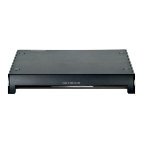
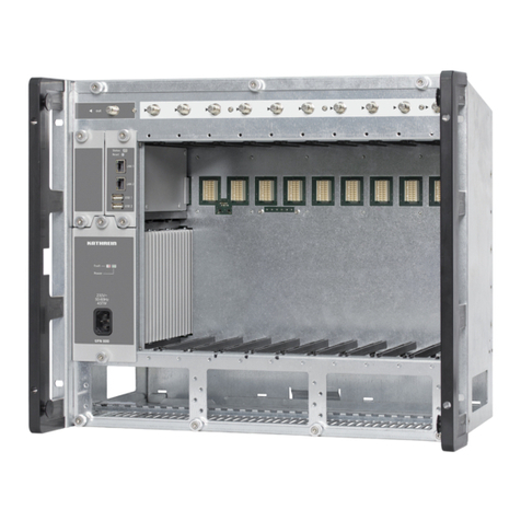
Kathrein UFO 340 User manual

936.2448/B/0705/1.8d
UFO®compact-Aufbereitungssystem
Twin-Sat-TV-Kanalzug
UFO 340
20610007
Twin-Sat-TV-Kanalzug zum Einbau in die
UFO®compact-Grund- und -Erweiterungseinheiten
UFG 3xx
Zur Aufbereitung von zwei unabhängigen Satelli-
tensignalen konventioneller TV-Norm (PAL,
SECAM) mit analogen Unterträgern und Umset-
zung in einen Ausgangsfrequenzbereich von
110-862 MHz
Nachbarkanal-tauglich
Für TV-Standards B/G, D/K, I
Rauschmindernde Sat-Unterträgeraufbereitung,
kompatibel zum Panda I-Verfahren der
Fa. Wegener
Tonbetriebsarten: Mono, Stereo, 2-Ton
Datenzeilen-Decoder zur automatischen Auswahl
der Tonbetriebsart (Mono, Stereo, 2-Ton)
C-Band-tauglich
FM-Schwelle: 7 dB
Ausgangspegel über die Steuerung der Grundein-
heit einstellbar
Ausgangssignal über die Steuerung abschaltbar
Mit Hilfe eines Sat-TV-Signals Schwarzbild-
erzeugung für einen Kanal (Twin A) möglich (z.B.
für Wiedergabe von Sat-Radioprogrammen im
TV-Kanal)
Decoder-Schnittstelle für einen Kanal (Twin A).
A/V-Signal mittels externer Schaltspannungen
(Decoder, Videorecorder) umschaltbar.
Konfiguration über die Steuerung möglich
1) Für Kanalzug Twin A und Twin B unabhängig in 1-MHz-Schritten einstellbar
2) Standards B/G, D/K und I wählbar. Außerdem Standard M (4,5-MHz-Bild-/Tonträgerabstand, Kanalraster entsprechend Standard B/G) wählbar
3) Einstellbar im 7-MHz- bzw. 8-MHz-Kanalraster (je nach Standard), Feineinstellung in 250-kHz-Schritten innerhalb des eingestellten Ausgangskanals möglich.
Die Einstellung erfolgt an Kanalzug Twin A. Die Ausgangsfrequenz von Kanalzug Twin B liegt immer 7 MHz bzw. 8 MHz höher als die Ausgangsfrequenz von Twin A
4) Der Pegel wird an Kanalzug Twin A eingestellt und ist für Twin B gleich.
Ausgangspegel von 92–100 dBµV (16 Kanäle) bzw. 92–98 dBµV (24 Kanäle) am Anlagenausgang einstellbar
5) Anpassbar an die Video-FM-Hübe 13,5/16/20/25 MHz
6) Mit Deemphase
7) Ohne Deemphase, zwischen Synchron- und Weißwert des nicht entzerrten Videosignals
8) Anpassbar an die Hübe 50 kHzs-420 kHzs, dazu erforderliche Deemphase (50, 75 µs, J17) wählbar
9) Für Hub der Begleittonträger am Geräteausgang 50 kHzs
10) Statisch
11) Tonträgerfrequenzen im 10-kHz-Raster einstellbar
12) Ab Gerätestand C 00 ändert sich die Stromaufnahme bei 5 V auf 1000 mA und bei 12,5 V auf 460 mA. Eine Änderung der Maximalbestückung ist nicht erforderlich.
Ausgang
(F-Connector-Buchse)
Feld für beigelegten
Aufkleber
Buchse zum
Anschließen der
Steuerung (Mini-DIN)
Decoder-
Schnittstelle
Anschluss für
Stromversorgungs-Bus
Sat-ZF-Eingang B
(F-Connector-Buchse)
Sat-ZF-Eingang A
(F-Connector-Buchse)
Frequenz Pegel/Impedanz Decoder- bzw. AV-Schnittstelle HF-Band FM- Sat-Ton- Versorgungs- Zul.
Eingang Ausgang2) Eingang Ausgang Pegel/Impedanz breite Schwelle träger- spannung/Typ. Umg.-
Kanal im 110–862 48–80 93 dBµV4)/ FBAS BB Audio FBAS Audio SAT frequenz Stromaufnahme Tempe-
Bereich MHz3) dBµV/ 75 Ohm (V/mA)12) ratur
920–2150 75 Ohm 1 Vss/ 1 Vss/ 1 Veff 1 Vss/ 1 Veff/ 27–36 MHz 7 dB10) 5,5– 5/1160 -20 °C
MHz1) 75 Ohm5) 75 Ohm5)6) 10 kOhm8) 75 Ohm 10 kOhm9) 9 MHz11) 12,5/390 bis
0,3 Vss asymm. asymm. 31/9 +50 °C
75 Ohm5)7)
Elektronische Geräte gehören nicht in den Hausmüll,
sondern müssen – gemäß Richtlinie 2002/96/EG
DES EUROPÄISCHEN PARLAMENTS UND DES
RATES vom 27. Januar 2003 über Elektro-und
Elektronik-Altgeräte fachgerecht entsorgt werden.
Bitte geben Sie dieses Gerät am Ende seiner
Verwendung zur Entsorgung an den dafür
vorgesehenen öffentlichen Sammelstellen ab.
Technische Daten

Twin A 1744 MHz
Ausg. K12 224,25 MHz
Stereo 7,02/7,20 MHz
Vol 3 Vid 2 AV
936.2448/B/0705/2.8d
Einstellanweisung
Die Einstellung des Twin-Sat-TV-Kanalzugs erfolgt über die Steuerung an der Grundeinheit UFG 308 bzw. UFG 312.
Erforderlicher Software-Stand der Steuerung: ab 7.00.
Erforderlicher Software-Stand der Steuerung ab Gerätestand C00: ab 8.01
Zum Einstellen ist die Steuerung an die Kassette (enthält Kanalzug Twin A und Twin B) anzuschließen.
Die im Folgenden genannten Tasten beziehen sich auf die Steuerung (siehe auch Anwendungshinweis der
Grundeinheiten UFG 308, UFG 312).
Hinweis:
Die hier dargestellten Einstellungen und Zahlenwerte sind als Beispiel zu verstehen und entsprechen nicht
zwingend dem Auslieferungszustand.
Der gewünschte Parameter wird durch die Tasten „” bzw. „” angewählt.
Der angewählte Parameter blinkt in der Anzeige.
Die Einstellung erfolgt mit den Tasten „+” bzw. „-”.
Abschließend wird mit der Taste M die Einstellung in der Kassette abgespeichert. Beim Trennen der Steuerung von der
Kassette ohne Abspeichern, werden die Einstellungen wieder aktiv, die in der Kassette gespeichert waren.
1. Anwahl des Kanalzugs Twin A oder Twin B
Die Anzeige bezieht sich immer auf einen der beiden, in der Kassette untergebrachten, Kanalzüge (A oder B).
Es wird also zuerst der Kanalzug ausgewählt, an dem Einstellungen vorgenommen werden sollen.
Hinweis:
Der Kanalzug mit der unteren Ausgangsfrequenz ist Twin A.
Twin A ist maßgebend für die Einstellung der Ausgangsfrequenz und des Ausgangspegels.
Mit den Tasten „<<” bzw. „>>” wird „Twin A“ oder „Twin B“
gewählt.
Twin A 1744 MHz
Ausg. K12 224,25 MHz
Stereo 7,02/7,20 MHz
Vol 3 Vid 2 AV
2. Konfiguration der Kanalzüge Twin A und Twin B
Die Wahl der Eingangsbuchse A/B für Kanalzug Twin B und die Abschaltung eines Kanalzugs erfolgen im Untermenü zur
Kanalzuganwahl. Dazu mit der Taste in das Untermenü wechseln.
Hauptmenü Untermenü Ausgang
*** UFO 340 ***
Eingang Twin A/B A/A
Ausgang Twin B Ein
< zurück: Untermenü.. >
Untermenü Ausgang
Twin B 1744 MHz
Ausg. K13 232,25 MHz
Stereo 7,02/7,20 MHz
Vol 3 Vid 2 AV
Hauptmenü
*** UFO 340 ***
Eingang Twin A/B A/A
Ausgang Twin A Ein
< zurück: Untermenü.. >

Twin A 1744 MHz
Ausg. K12 224,25 MHz
stereo 7,02/7,20 MHz
Vol 3 Vid 2 AV
936.2448/B/0705/3.8d
Der gewünschte Parameter wird durch die Tasten „” bzw. „” angewählt.
Dieser Parameter ist für beide Kanalzüge gleich. Einstellbar im Untermenü von Twin A oder Twin B. Es gibt drei verschie-
dene Einstellmöglichkeiten.
A/A = Twin A und Twin B sind auf Eingang A geschaltet
A/B = Twin A ist auf Eingang A und Twin B ist auf Eingang B geschaltet
B/B = Twin A und Twin B sind auf Eingang B geschaltet
Damit wird der gleichzeitige Betrieb der Kanalzüge Twin A und Twin B an verschiedenen Polarisationen ermöglicht.
Hinweis:
Sat-ZF-Signale von unterschiedlichen Polarisationsebenen sind mit gleichem Pegel (Toleranz: ± 2 dB) an die Eingänge A
und B anzuschließen.
Mit den Tasten „+” bzw. „-” kann „HF Ein“ oder „HF Aus“ gewählt werden.
Die Abschaltung eines Kanalzuges bewirkt, dass er stillgelegt wird und kein Ausgangssignal erzeugt.
Die Einstellung der Ausgangsfrequenz (s.u.) und die Pegeleinstellung ist nur möglich, wenn Twin A angewählt ist. Das gilt
auch, wenn Kanalzug Twin A abgeschaltet ist.
Ist ein Kanalzug abgeschaltet, zeigt das Hauptmenü folgende Anzeige:
Hauptmenü Twin A (abgeschaltet) Hauptmenü Twin B (abgeschaltet)
Twin B AUS
Der Kanalzug Twin A kann bei abgeschaltetem Ausgangssignal noch als Demodulator mit A/V-Ausgang (Decoder-
Schnittstelle) verwendet werden. Daher werden für Kanalzug Twin A noch alle Parameter angezeigt und die
Ausgangskanalanzeige mit einem * gekennzeichnet (Kennzeichen für abgeschaltetes Ausgangssignal).
oder
Twin A 1744 MHz
Ausg. *K12 224,25 MHz
stereo 7,02/7,20 MHz
Vol 3 Vid 2 AV
3. Wahl der Eingangsfrequenz
Mit den Tasten „+” bzw. „-” kontinuierlich in 1-MHz-Schritten
von 950 MHz bis 2150 MHz einstellbar.
Die Eingabe kann auch stellenweise erfolgen:
Die Tasten „” und „” gleichzeitig drücken und wieder
loslassen (startet den Modus)
Mit den Tasten „” und „” die Stelle anwählen
(angewählte Stelle blinkt)
Mit den Tasten „+” bzw. „-” die Stelle einstellen.
In dieser Weise werden alle Stellen gewählt und eingestellt
Die Tasten „” und „” gleichzeitig drücken und wieder
loslassen (beendet den Modus)
Twin A: 1744 MHz
Ausg. K12 224,25 MHz
Stereo 7,02/7,20 MHz
Vol 3 Vid 2 AV
4. Wahl der Ausgangsfrequenz bzw. des Ausgangskanals
Hauptmenü Untermenü Ausgang
*** UFO 340 ***
Ausg. Freq. 224,25 MHz
Ausg. Pegel -12 Norm B/G
< Zurück: Untermenü.. >

*** UFO 340 ***
Ausg. Freq. 224,25 MHz
Ausg. Pegel -15 Norm B/G
< Zurück: Untermenü.. >
936.2448/B/0705/4.8d
Hinweis:
Diese Einstellung ist nur möglich, wenn Kanalzug Twin A angewählt ist.
Die Ausgangsfrequenz des Kanalzuges Twin B ist fest mit der Einstellung des Kanalzugs Twin A verknüpft und nicht
gesondert einstellbar: fAusgang_B = fAusgang_A + 7 MHz (Norm B).
fAusgang_B = fAusgang_A + 8 MHz (Norm G, D, K, I)
Mit den Tasten „+” bzw. „-” kontinuierlich in 7-MHz- bzw. 8-MHz-Schritten von 111,25 MHz bis 847,25 MHz einstellbar
(je nach Standard). Bei den TV-Standards D/K und I erfolgt die Kanalanzeige bei den Sonderkanälen durch „---“.
Die Feineinstellung der Ausgangsfrequenz in 250-kHz-Schritten ist im Untermenü zur Ausgangsfrequenz möglich.
Dazu mit der Taste in das Untermenü wechseln und mit den Tasten „+” bzw. „-” die gewünschte Frequenz einstellen.
Durch Drücken der Taste wird das Untermenü wieder verlassen.
5. Wahl des Ausgangspegels
Mit den Tasten „+” bzw. „-” kontinuierlich in 40 Schritten einstellbar. Die Einstellgrenzen sind mit „Min“ und „Max“
gekennzeichnet (vergleichbar mit Links- und Rechtsanschlag eines herkömmlichen Dämpfungswählers).
Die Einstellung des Ausgangspegels ist im Untermenü zur Ausgangsfrequenz möglich. Dazu mit der Taste
in das Untermenü wechseln und mit den Tasten „+” bzw. „-” den gewünschten Pegel einstellen.
Durch Drücken der Taste wird das Untermenü wieder verlassen.
Hinweis:
Diese Einstellung ist nur möglich, wenn Kanalzug Twin A angewählt ist.
Der Ausgangspegel des Kanalzuges Twin B ist fest mit der Einstellung des Kanalzuges Twin A verknüpft und im Rahmen
der angegebenen Genauigkeit gleich hoch.
Untermenü AusgangHauptmenü
Twin A 1744 MHz
Ausg. K12 224,25 MHz
Stereo 7,02/7,20 MHz
Vol 3 Vid 2 AV
*** UFO 340 ***
Ausg. Freq. 224,25 MHz
Ausg. Pegel -12 Norm I
< Zurück: Untermenü.. >
6. Wahl des TV-Standards
TV-Standard im Untermenü mit der Taste „+” oder „-” der Steuerung wählen. Wählbar sind die TV-Standards B/G, D/K
und I. Zusätzlich ist noch der Standard M einstellbar, jedoch nur im Kanalraster gemäß Standard B bzw. G mit 4,5-MHz-
Bild-/Tonträgerabstand.
Untermenü AusgangHauptmenü
Twin A: 1744 MHz
Ausg. K12 224,25 MHz
Stereo 7,02/7,20 MHz
Vol 3 Vid 2 AV

*** UFO 340 ***
Ton1/Ton2 tauschen:
7,20/7,02 MHz
< Zurück: Untermenü.. >
Twin A: 1744 MHz
Ausg. K12 224,25 MHz
2Ton 7,02/7,20 MHz
Vol 3 Vid 2 AV
Twin A: 1744 MHz
Ausg. K12 224,25 MHz
Stereo 7,02/7,20 MHz
Vol 3 Vid 2 AV
936.2448/B/0705/5.8d
7. Wahl der Tonbetriebsart
Betriebsarten-Umschaltung mit den Tasten „+ oder -“ der
Steuerung (Auswahl „Mono“, „Stereo“, „2-Ton“ oder „Auto“).
In der Tonbetriebsart „Mono“ besteht die Wahlmöglichkeit der
Sat-Tonträger-Betriebsart („Sub“ oder „Main“, siehe Punkt 9)
Hinweis zur Betriebsart „Auto“:
Nur für Sat-Programme mit VPS-Signal (Datenzeile) verwenden
Darstellung abhängig vom Inhalt der Datenzeile „Auto S“ (Stereo), „Auto Z“ (2-Ton), „Auto M“ (Mono)
Bei fehlendem VPS-Signal wird automatisch auf Betriebsart „2-Ton“ (Darstellung als „Auto *Z“) umgeschaltet.
Sat-Tonträgerfrequenzen bei Betriebsart „Auto“ nicht veränderbar
Bei allen deutschsprachigen Programmen mit Videotext wird auch das VPS-Signal ausgestrahlt.
Bei diesen Programmen empfiehlt sich generell die Einstellung „Auto“. Je nach eingestellter Betriebsart erfolgt in der
Kassette automatisch die Umschaltung.
Hinweis zur Betriebsart „2-Ton“:
In der Betriebsart „2-Ton“ können im Untermenü die Sat-Tonträgerfrequenzen getauscht werden.
Zweck: Tausch von Ton 1 und Ton 2 bei mehrsprachigen Programmen, wie z. B. Eurosport.
Hinweis zu den TV-Standards:
Die Aufbereitung des TV-Begleittons in Stereo ist nur möglich, wenn als Standard B/G ausgewählt ist.
Ist ein anderer TV-Standard (D/K, I oder M) ausgewählt, erfolgt die Aufbereitung des Begleittons in Mono.
Liegt der Sat-Begleitton in Stereo vor, erfolgt bei Einstellung „Stereo“ oder „Auto“ („Auto S“) automatisch die
Aufbereitung des ausgangsseitigen Monosignals per Summenbildung ((L+R)/2) aus dem Sat-Stereosignal.
Twin A: 1744 MHz
Ausg. K12 224,25 MHz
Stereo 7,02 MHz Sub
Vol 3 Vid 2 AV
Betriebsartenumschaltung mit den Tasten „+” oder „-” der
Steuerung.
Auswahl zwischen:
Betriebsart „Sub“ (Einstellung für Panda I-Unterträger)
Betriebsart „Main“ (Einstellung für Haupttonträger,
z. B. EUTELSAT)
Einstellung ist nur in Betriebsart „Mono“ möglich. In den Tonbe-
triebsarten „Stereo“, „2-Ton“, „Auto“ ist daher immer automatisch
die Betriebsart „Sub“ eingestellt.
Twin A: 1744 MHz
Ausg. K12 224,25 MHz
Stereo 7,02/7,20 MHz
Vol 3 Vid 2 AV
8. Wahl der Sat-Tonträgerfrequenz
In den Betriebsarten „Stereo“ und „2-Ton“ ist die zweite Sat-Ton-
trägerfrequenz an die erste gekoppelt (180-kHz-Abstand).
Sat-Tonträgerfrequenz (5,5–9 MHz) ist mit der Taste „+” oder „-”
der Steuerung einstellbar.
9. Wahl der Sat-Tonträgerbetriebsart
Untermenü 2-TonHauptmenü

Twin A: 1744 MHz
Ausg. K12 224,25 MHz
Stereo 7,02/7,20 MHz
Vol 3 Vid 2 AV
Twin A: 1744 MHz
Ausg. K12 224,25 MHz
Stereo 7,02/7,20 MHz
Vol 3 Vid 2 AV
936.2448/B/0705/6.8d
10. Wahl der Tonlautstärke bzw. des Sat-Tonträgerhubes
Einstellung mit den Tasten „+” oder „-” der Steuerung.
Zur Korrektur der Tonlautstärke in den Tonbetriebsarten „Mono
Sub“, „Stereo“, „2-Ton“, „Auto“:
Vol 1 = - 6 dB
Vol 2 = - 3 dB
Vol 3 = 0 dB
Vol 4 = + 3 dB
Zur Anpassung des Sat-Tonträgerhubes in der Tonbetriebsart
„Main“: Vol 1 = 420 kHzs
Vol 2 = 140 kHzs
Vol 3 = 85 kHzs
11. Wahl der Ton-Deemphase
Diese Einstellmöglichkeit besteht nur in der Sat-Tonträgerbetriebs-
art „Main“.
Einstellbar mit den Tasten „+” oder „-” der Steuerung
(„50 µs“, „75 µs“ oder „J17“)
12. Wahl des Videohubes
Einstellbar mit den Tasten „+” oder „- ” der Steuerung.
Zur Anpassung an folgende FM-Hübe:
Vid 1 = 13,5 MHz
Vid 2 = 16 MHz
Vid 3 = 20 MHz
Vid 4 = 25 MHz
Twin A: 1744 MHz
Ausg. K12 224,25 MHz
Stereo 6,65 MHz Main
50 µs Vol 3 Vid 2 AV
*** UFO 340 ***
Videopolarität positiv
< Zurück: Untermenü.. >
Twin A: 1744 MHz
Ausg. K12 224,25 MHz
2Ton 7,02/7,20 MHz
Vol 3 Vid 2 AV
13. Wahl der Videopolarität
Mit den Tasten „+” oder „-” der Steuerung kann entweder „negativ“ (Normalfall) oder „positiv“ (C-Band-Transponder)
eingestellt werden.
Untermenü Vid2Hauptmenü

*** UFO 340 ***
Video intern
Audio extern
< Zurück: Untermenü.. >
936.2448/B/0705/7.8d
14. Betriebsart der AV- bzw. Decoder-Schnittstelle
Beschaltung der Submin D-Buchse
Einstellung mit den Tasten „+” und „-” der Steuerung. Wählbar sind die Betriebszustände:
„intern“ Video- und Audiosignal sind geräteintern durchverbunden. Mittels externer Schaltspannungen (+12 V),
z. B. von einem Decoder oder einem Videorecorder, kann die Decoder-Schnittstelle umgeschaltet werden
(Unterbrechung des geräteinternen Signalweges).
Anwendungsbeispiele: - Betrieb mit Decoder
- Betrieb mit Videorecorder oder Videokamera
„extern“ Geräteinterner Signalweg ist unterbrochen, externe Schaltspannungen haben keinen Einfluss.
Für A/V-Signalquellen, die keine Schaltspannung liefern können.
Beide Betriebsarten können für Video und Audio getrennt ausgewählt werden.
Ferner kann bei dem Parameter „Video“ noch der Zustand „Schwarzbild“ ausgewählt werden (ab Gerätestand C 00 auch
bei Twin B möglich). Damit kann aus einem empfangenen Sat-TV-Signal ein Schwarzbild erzeugt werden, um
Sat-Radio-Signale in einem TV-Kanal zu übertragen
über die A/V-Schnittstelle eingespeiste Audiosignale (z. B. CD-Player) in einem TV-Kanal zu übertragen
Twin A: 1744 MHz
Ausg. K12 224,25 MHz
2Ton 7,02/7,20 MHz
Vol 3 Vid 2 AV
Untermenü A/VHauptmenü
Pin 1 2 3 4 5 6 7 8 11 12 13
Signal Audio FBAS- Video- Basis- FBAS- Audio- Audio- Masse Masse Audio- Audio-
Eingang Eingang; schalt- band- Ausgang Eingang schalt- Ausgang Ausgang
links Video signal Ausgang rechts signal links rechts
geklemmt 0/12 V 0/12 V
Kanal 7 Kanal 8 Kanal 9 Kanal 10
belegt mit soll belegt werden belegt mit soll belegt werden
UFO 335 UFO 335
Kanal 7 Kanal 8 Kanal 9 Kanal 10
belegt mit UFO 340 UFO 340 UFO 335
UFO 335
Mischbetrieb von UFO 340 mit UFO 335/365, Einsatz in älteren Grund- und
Erweiterungseinheiten
1. Mit dem UFO 340 ist der obere Nachbarkanal mit der Auswahl des unteren bereits vorgegeben
(Zwangsnachbarkanal-Belegung)
In bereits bestehenden Anlagen kann folgende Situation gegeben sein.
Lösung mit UFO 340:
Ein UFO 335 muss dabei von Kanal 9 auf Kanal 10 umprogrammiert werden. Soll nur Kanal 8 belegt werden, ist das be-
treffende Ausgangssignal des UFO 340 entsprechend abzuschalten.
2. Bei Ergänzung bestehender Anlagen (noch mit Netzteil BN 1681794) mit UFO 340 ist zu beachten, dass das Netzteil
eine geringere Strombelastbarkeit hat. Daher auf die Stromaufnahme-Angaben auf dem Aufkleber des Netzteils achten.

936.2448/B/0705/8.8d/SKS Technische Änderungen vorbehalten.
KATHREIN-Werke KG · Anton-Kathrein-Straße 1–3 · Postfach 10 04 44 · D-83004 Rosenheim · Deutschland · Telefon (0 80 31) 18 40 · Telefax (0 80 31) 18 43 06
Internt: http//www.kathrein.de
Anwendung

Twin Sat TV channel unit for use in UFO®compact
base and extension units UFG 3xx
For processing of two independent satellite signals
in conventional TV standards (PAL, SECAM) with
analogue subcarriers and conversion to the output
frequency range from 110 MHz to 862 MHz
Adjacent channel compatible
For TV standards B/G, D/K, I
Noise-reducing Sat subcarrier processing,
compatible with Wegener Panda I
Audio operating mode: Mono, stereo, dual
sound
Data line decoder for automatic selection of the
audio operating mode (mono, stereo, dual sound)
C-band compatible
FM threshold: 7 dB
Output level is adjustable via the control unit of the
base module carrier
Output signal can be disengaged via the control
unit
A Sat TV signal enables generation of a black
screen for a channel (Twin A)
(e.g. for reproduction of Sat radio programmes via
a TV channel)
Decoder interface for one channel (Twin A).
A/V signal is switchable by means of external
switching voltages (decoder, video recorder).
Configuration is possible via the control unit
936.2448/B/0705/1.8e
UFO®compact Processing System
Twin Sat TV channel unit
UFO 340
20610007
Technical data
Frequency Level/Impedance Decoder or AV interface RF band- FM- Sat- Supply voltage/ Amb.
Input Output2) Input Output Level/Impedance width thres- Audio voltage/typ. temper-
Channel in 110–862 48–80 93 dBµV4)/ Comp. BB Audio Comp. Audio SAT hold carrier current drain ature
the range of MHz3) dBµV/ 75 Ohm colour colour frequency (V/mA)12) limit
920–2150 75 Ohm 1 Vss/ 1 Vss/ 1 Veff 1 Vss/ 1 Veff/ 27–36 MHz 7 dB10) 5.5– 5/1160 -20 °C
MHz1) 75 Ohm5) 75 Ohm5)6) 10 kOhm8) 75 Ohm 10 kOhm9) 9 MHz11) 12.5/390 to
0.3 Vss asymm. asymm. 31/9 50 °C
75 Ohm5)7)
1) Independently adjustable in 1 MHz steps for channel unit twin A and twin B
2) Standards B/D, G/K and I are selectable. Standard M is also selectable (4.5 MHz video/audio carrier spacing, channel plan is selectable according to the standard B/G)
3) Adjustable in the 7 MHz or 8 MHz channel plan (each according to the standard), Fine tuning is possible in 250 kHz steps within the output channel which was set.
The setting is carried out on channel unit twin A. The output frequency of channel unit twin B is always 7 MHz or 8 MHz higher than the output frequency of twin A
4) The level is adjusted on the channel unit twin A and is the same for twin A and twin B. Output level from 92–100 dBµV (16 channels) or 92–98 dBµV (24 channels) on the
system output is adjustable
5) Adaptable to video FM deviations 13.5/16/20/25 MHz
6) With de-emphasis
7) Without de-emphasis, between synchronous and white level of the video signal which is not equalised
8) Adaptable to the deviations 50 kHzs-420 kHzs, required de-emphasis (50, 75µs, J17) can be selected
9) 50 kHzp for deviation of the accompanying audio carriers on the output
10) Static
11) Audio carrier frequencies can be set in 10 kHz steps
12) From version C00 on, the power consumption changes at 5 V to 10 mA, and at 12.5 V to 460 mA. Changing the maximum equipment ist not necessary.
Output
(F-connector, female)
Place for supplied
sticker
Connector for
control unit (mini-DIN))
Decoder interface
Connection for
power supply bus
Sat IF input B
(F-connector, female)
Sat IF input A
(F-connector, female)
Electronic equipment is not household waste –
in accordance with directive 2002/96/EC OF THE
EUROPEAN PARLIAMENT AND THE COUNCIL of
27th January 2003 on used electrical and electronic
equipment, it must be disposed of properly.
At the end of its service life, take this unit for
disposal at a relevant official collection point.

Twin A 1744 MHz
Outp. Ch12 224.25 MHz
Stereo 7.02/7.20 MHz
Vol 3 Vid 2 AV
936.2448/B/0705/2.8e
Setting instructions
The Twin Sat TV channel unit is adjusted via the control unit of the base module carrier UFG 308 or UFG 312.
Required software version of the control unit: at least 7.00
Required software version ot the control unit from version C00 on: at least 8.01
For adjustment, it is necessary to connect the control unit to the module (consists of channel unit twin A and twin B).
The following listed keys are on to the control unit (also refer to operating instructions for the base module carriers UFG
308, UFG 312).
Note: The settings and values shown are just examples and do not necessarily coincide with the delivery status
of the unit.
The desired parameter is selected with the ”“ and ”“ keys.
The selected parameter flashes in the display.
The setting is carried out with the “+” or “-“ key.
After all parameters have been set, the setting is saved in the module with the M key. When disconnecting the control
unit from the module without having saved the setting, the settings which had been saved before, become active again.
1. Selecting the channel unit twin A or twin B
The display always refers to one of the two channel units integrated in the module (A or B).
The channel unit in which the settings are to be carried out is called up first.
Note:
The channel unit with the lower output frequency is twin A.
Twin A is competent for setting the output frequency and the output level.
”Twin A“ or ”Twin B“ is selected with the >> or << key.
Twin A 1744 MHz
Outp. Ch12 224.25 MHz
Stereo 7.02/7.20 MHz
Vol 3 Vid 2 AV
2. Configuration of the channel units twin A and twin B
Selection of input connector A or B for channel unit twin B and switch-off of a channel unit is effected in the submenu
for channel unit selection. For this purpose, enter the submenu by pressing the key.
Main menu Submenu output
*** UFO 340 ***
Input Twin A/B A/A
Output Twin B On
< Return: Submenu.. >
Submenu output
Twin B 1744 MHz
Outp. Ch13 232.25 MHz
Stereo 7.02/7.20 MHz
Vol 3 Vid 2 AV
Main menu
*** UFO 340 ***
Input Input A/B A/A
Output Twin A On
< Return: Submenu.. >

Twin A 1744 MHz
Outp. Ch12 224.25 MHz
stereo 7.02/7.20 MHz
Vol 3 Vid 2 AV
936.2448/B/0705/3.8e
This parameter is the same for both channel units. Settable in the submenu of Twin A or Twin B. There are three different
setting possibilities:
A/A = Twin A and Twin B are switched to input A
A/B = Twin A is switched to input A and Twin B to input B
B/B = Twin A and Twin B are switched to Twin B
This allows for the operation of channel units Twin A and Twin B on different polarities at the same time.
Note: Sat IF signals from different polarisation planes are to be connected to the inputs A and B with the same level
(tolerance ± 2 dB).
“RF on” or “RF off” can be selected with the “+” or “–“ keys.
Switching off a channel unit causes it to shut down and no output signal is produced.
The setting of the output frequency (see below) and the level setting is only possible, if twin A is selected. This also
applies when the channel unit twin A is switched off.
If a channel unit is switched off, the main menu shows the following display:
Main menu twin A (switched off) Main menu twin B (switched off)
Twin B OFF
The channel unit twin A can be used as a demodulator with A/V output (decoder interface) for the disengaged output
signal. All parameters for channel unit twin A are still displayed, and the output channel display is marked with a *
(indicator for disconnected output signal).
or
Twin A 1744 MHz
Outp. *Ch12 224.25 MHz
stereo 7.02/7.20 MHz
Vol 3 Vid 2 AV
3. Selecting the input frequency
The input frequency is selectable in 1 MHz steps between
950 MHz and 2150 MHz with the ”+” or ”-” key.
Changing the entry by numeric character entry is also possible:
Press and release the ”” and ”” keys at the same time
(mode starts).
Select the position with the ”“ and ”” keys
(the selected position flashes).
Set the position with the ”+” or ”-” key.
In this manner, all the positions are selected and set.
Press and release the ”” and ”” keys at the same time
(mode ends).
Twin A: 1744 MHz
Outp. Ch12 224.25 MHz
Stereo 7.02/7.20 MHz
Vol 3 Vid 2 AV
4. Selecting the output frequency or output channel
Main menu Submenu output
*** UFO 340 ***
Outp. freq. 224.25 MHz
Outp. level -12 Standard B/G
< Return: Submenu.. >
The desired parameter is selected with the ”“ and ”“ key.

*** UFO 340 ***
Outp. freq. 224.25 MHz
Outp. level -12 Standard I
< Return: Submenu.. >
*** UFO 340 ***
Outp. freq. 224.25 MHz
Outp. level -15 Standard B/G
< Return: Submenu.. >
936.2448/B/0705/4.8e
Note:
This setting is only possible, if the channel unit twin A is selected.
The output frequency of the channel unit twin B is determined once the output frequency of the channel unit twin A is set
and cannot be adjusted separately: fOutput_B = fOutput_A + 7 MHz (Standard B).
fOutput_B = fOutput_A + 8 MHz (Standard G, D, K, I)
Can be adjusted in 7 MHz or 8 MHz steps (depending on the standard) between 111.25 MHz and 847.25 MHz with the
“+” or “-“ key. For standards D/K and I, the channel display for special channels is shown as „-----“.
The fine tuning of the output frequency in 250 kHz steps is possible in the submenu of the output frequency. Enter the
submenu with the key, and set the desired frequency with the “+” or “–“ key.
Exit the submenu again by pressing the key.
5. Selecting the output level
The output level can be adjusted in 40 steps with the “+” or “–“ key. The adjustment limits are marked with “Min” and
“Max” (comparable to the left and right stopping point of a conventional variable attenuator).
The setting of the output level is possible in the submenu of the output frequency. To do this, enter the
submenu with the key and set the desired level with the “+” or “–“ key.
Exit the submenu by pressing the key again.
Note:
The setting is only possible if channel unit twin A is selected. The output level of the channel unit twin B is determined
once the output level of the channel unit twin A is set and is practically identical to the set value.
Submenu outputMain menu
Twin A 1744 MHz
Outp. Ch12 224.25 MHz
Stereo 7.02/7.20 MHz
Vol 3 Vid 2 AV
6. Selecting the TV standard
Select the TV standard in the submenu with the “+” or “-“ key on the control unit. The TV standards B/G,D/K and I can
be selected. In addition, the standard M can also be set, however, only in the channel plan according to the standard B
or G with 4.5 MHz video/audio carrier spacing.
Submenu outputMain menu
Twin A: 1744 MHz
Outp. Ch12 224.25 MHz
Stereo 7.02/7.20 MHz
Vol 3 Vid 2 AV

Twin A: 1744 MHz
Outp. Ch12 224.25 MHz
Dual sound 7.02/7.20 MHz
Vol 3 Vid 2 AV
*** UFO 340 ***
Audio carrier swap:
7.20/7.02 MHz
< Return: Submenu.. >
Twin A: 1744 MHz
Outp. Ch12 224.25 MHz
Stereo 7.02/7.20 MHz
Vol 3 Vid 2 AV
936.2448/B/0705/5.8e
7. Selecting the audio operating mode
The operating mode can be changed via the control unit with the
“+” or “-“ key (Selection “mono,” “stereo,” “dual sound” or
“auto”).
In the audio operating mode “mono”, the Sat audio carrier
operating mode can be selected (“sub” or “main,” see item 9).
Instructions regarding the operating mode “auto”
Only use for Sat programmes with VPS signals (data line).
Representation depends on the contents of the data line “Auto S” (Stereo), “Auto Z” (dual sound), “Auto M” (mono).
If the VPS signal is missing, automatic switch-over to operating mode “dual sound” is effected (displayed as
“Auto*Z”).
The Sat audio carrier frequencies cannot not be changed in the operating mode “Auto.”
For all programmes in German with teletext, the VPS signal is also transmitted. For these programmes, it is recom-
mended to set the operating mode “auto.” Automatic switch-over in the module according to the set operating mode
is effected.
Note regarding operating mode “dual sound”:
In the operating mode “dual sound“, the Sat audio carrier frequencies can be changed in the submenu.
Purpose: Switching between sound 1 and sound 2 for multilingual programmes (e.g. Eurosport).
Note regarding the TV standards:
The processing of the TV accompanying sound is only possible in stereo, if standard B/G is selected.
If another TV standard (D/K, I or M) is selected, the processing of the accompanying sound is effected in mono. If the
Sat accompanying sound is in stereo, the processing of the mono signal on the output side is automatically effected per
summation ((L+R)/2) from the Sat stereo signal for the setting “stereo“ or “auto” (“Auto S”).
Twin A: 1744 MHz
Outp. Ch12 224.25 MHz
Stereo 7.02 MHz Sub
Vol 3 Vid 2 AV
Switch-over of the operating mode is carried out via the control
unit with the “+” or “-“ key. Select between:
Operating mode “Sub” (setting for Panda I subcarrier).
Operating mode “Main” (setting for main audio carrier,
e.g. EUTELSAT).
The setting is only possible in the operating mode “mono.”
In the audio operating modes, “stereo,” “dual sound” and “auto,”
the operating mode “Sub” is always automatically set.
Twin A: 1744 MHz
Outp. Ch12 224.25 MHz
Stereo 7.02/7.20 MHz
Vol 3 Vid 2 AV
8. Selecting the Sat audio carrier frequency
The second Sat audio carrier frequency has a fixed spacing of
180 kHz to the first carrier in the operating mode “stereo” and
“dual sound.”
The Sat audio carrier frequency (5.5 - 9 MHz) can be adjusted via
the control unit with the “+” or “-“ key.
9. Selecting the Sat audio carrier operating mode
Submenu dual soundMain menu

Twin A: 1744 MHz
Outp. Ch12 224.25 MHz
Stereo 7.02/7.20 MHz
Vol 3 Vid 2 AV
Twin A: 1744 MHz
Outp. Ch12 224.25 MHz
Stereo 7.02/7.20 MHz
Vol 3 Vid 2 AV
936.2448/B/0705/6.8e
10. Selecting the volume or the Sat audio carrier deviation
Setting is carried out via the control unit with the “+” or “-” key.
To correct the volume in the audio operating modes “mono sub,”
“stereo,” “dual sound” and “auto:”
“Vol 1” = -6 dB
“Vol 2” = -3 dB
“Vol 3” = 0 dB
“Vol 4” = +3 dB
For matching the Sat audio carrier deviation in the audio operating
mode “Main:”
“Vol 1” = 420 kHzs
“Vol 2” = 140 kHzs
“Vol 3” = 85 kHzs
11. Selecting the audio de-emphasis
This setting is only possible in the Sat audio carrier operating
mode “Main:”
The setting can be adjusted via the control unit with the “+” or “-“
key (“50µs,” “75µs” or “J17”).
12. Selecting the video deviation
The setting can be adjusted via the control unit with the “+” or “-“
key.
For adjustment to the following FM deviations:
“Vid 1” = 13.5 MHzp
“Vid 2” = 16 MHzp
“Vid 3” = 20 MHzp
“Vid 4” = 25 MHzp
Twin A: 1744 MHz
Outp. Ch12 224.25 MHz
Stereo 6.65 MHz Main
50 µs Vol 3 Vid 2 AV
*** UFO 340 ***
Video polarity positive
< Return: Submenu.. >
Twin A: 1744 MHz
Outp. Ch12 224.25 MHz
Dual sound 7.02/7.20 MHz
Vol 3 Vid 2 AV
13. Selecting the video polarity
Submenu Vid 2Main menu
”Negative” (normal) or ”positive“ (C-band transponder) can be set via the control unit with the ”+ ” or ”-” key.

*** UFO 340 ***
Video internal
Audio external
< Return: Submenu.. >
Mixed operation of UFO 340 with UFO 335/365 in older base and extension units
1) For the UFO 340, the upper adjacent channel is already pre-set once the lower channel is selected (forced adjacent
channel assignment).
In existing systems, the following situation can occur:
Solution with UFO 340:
936.2448/B/0705/7.8e
14. Operating mode of the AV or decoder interface
Wiring of the Submin D connector
The setting is carried out via the control unit with the “+” or “-“ key. The following operating modes are selectable:
“internal” Video and audio signal are circuited together within the unit. By means of external switching voltages
(+12 V), e.g. from a decoder or a video recorder, the decoder interface can be switched over (interrupti-
on of the signal path within the unit).
Examples: – Operation with decoder
– Operation with video recorder or video camera
„external“ Signal path within the unit is interrupted, external breaking voltages have no effect. Intended for A/V
signal sources which cannot supply a switching voltage.
Both operating modes can be separately selected for video and audio.
Moreover, the status “Black screen” can be selected for the parameter “video.” From version C00 also possible at
Twin B. A black screen can be produced from a received Sat TV signal, in order
to transmit Sat radio signals via a TV channel
to transmit audio signals fed-in via the A/V interface (e.g. CD-player), via a TV channel
Twin A: 1744 MHz
Outp. Ch12 224.25 MHz
Dual sound 7.02/7.20 MHz
Vol 3 Vid 2 AV
Submenu A/VMain menu
Pin 1 2 3 4 5 6 7 8 11 12 13
Signal Audio Comp. Video Base- Comp. Audio Audio Earth Earth Audio Audio
input colour switching band colour input switching output output
left input; signal output output right signal left right
Video 0/12 V 0/12 V
weighted
Channel 7 Channel 8 Channel 9 Channel 10
Occupied with Should be Occupied with Should be
UFO 335 occupied UFO 335 occupied
Channel 7 Channel 8 Channel 9 Channel 10
Occupied with UFO 340 UFO 340 UFO 335
UFO 335
One UFO 335 must be reprogrammed from channel 9 to channel 10. If only channel 8 is occupied, the corresponding
output signal of the UFO 340 must be disengaged.
2) When extending existing systems (equipped with the power supply unit, order no. 1681794) with UFO 340, take into
consideration, that the power supply unit has a reduced power consumption. Please observe the information regard-
ing the power consumption on the sticker on the power supply unit!

936.2448/B/0705/8.8e/SKS Subject to technical changes.
KATHREIN-Werke KG · Anton-Kathrein-Straße 1–3 · P.O Box 10 04 44 · D-83004 Rosenheim · Germany · Tel. +49 (0) 80 31 18 40 · Fax +49 (0) 80 31)18 43 06
Internt: http//www.kathrein.de
Installation
Remote feed
diplexer
IF IF IF IF IF IF Control unit
Remote feed
diplexer
IF IF IF IF IF IF Control unit

Voie jumelle de traitement de signaux TV Sat
destinée à l’installation dans les ensembles de
base et d’extension UFO®compact UFG 3xx
Pour le traitement de deux signaux satellite
des normes conventionnelles TV (PAL, SECAM)
avec des sous-porteuses analogiques et
conversion dans la gamme de sortie de 110 MHz
à 862 MHz
Utilisable en canaux adjacents
Les normes B/G, D/K et I sont sélectionnables
Traitement de sous-porteuses Sat à réduction de
bruit, compatible au procédé Panda I de la
société Wegener
Modes audio: Mono, stéréo, double son
Bande C compatible
Seuil FM: 7 dB
Niveau de sortie réglable via l’unité de contrôle
Signal de sortie déconnectable par l’unité de
contrôle
Possibilité de produire une image d’obscurité
pour un canal (Twin A) à l’aide d’un signal TV
(p. ex. pour un programme radio satellite via un
canal TV)
Interface décodeur pour un canal Twin A. Signal
A/V commutable par des tensions externes
(décodeur, magnétoscope)
936.2448/B/0705/1.8f
Système UFO®compact
Voie jumelle Sat TV
UFO 340
20610007
Données techniques
Fréquence Niveau/Impédance Interface décodeur ou vidéo Largeur Seuil Excursion Tension Température
Entrée Sortie2) Entrée Sortie Niveau/Impédance de bande FM d’alimen./ ambiante
1 canal dans 110–862 48–80 93 dBµV4)/ FBAS BB Audio FBAS Audio (Sat) Cons.typ. admis.
la gamme MHz3) dBµV/ 75 Ohm (V/mA)12)
920–2150 75 Ohm 1 Vss/ 1 Vss/ 1 Veff 1 Vss/ 1 Veff/ 27–36 MHz 7 dB10) 5.5– 5/1160 -20 °C
MHz1) 75 Ohm5) 75 Ohm5)6) 10 kOhm8) 75 Ohm 10 kOhm9) 9 MHz11) 12.5/390 à
0.3 Vss asymm. asymm. 31/9 50 °C
75 Ohm5)7)
1) Réglable indépendamment au pas de 1 MHz pour la jumelle A et B
2) Les normes B/G, D/K et I sont sélectionnables. La norme M est aussi sélectionnable (écart porteuse image/son 4,5 MHz, grille de canaux selon norme B/G)
3) Sélectionnable au plan des canaux 7 MHz ou 8 MHz (selon la norme). Réglage fin au pas de 250 kHz du canal choisi est possible
Le réglage s’effectue sur la jumelle A. La fréquence de sortie de la jumelle B est toujours de 7 MHz ou 8 MHz plus haute que la fréquence de sortie de la jumelle A
4) Le niveau est réglé sur la jumelle A et est égal pour la jumelle B.
Le niveau de sortie de 92–100 dBµV (16 canaux) ou 92–98 dBµV (24 canaux) est réglable en sortie multiplexeur au moyen de l’atténuateur de sortie
5) Adaptable aux excursions Vidéo FM de 13,5/16/20/25 MHz
6) Avec désaccentuation
7) Sans désaccentuation, entre les valeurs synchrone et blanche du signal Vidéo ne pas égalisé
8) Adaptable aux excursions 50 kHzc–240 KHzc, la désaccentuation nécessaire (50, 75 µs, J17) est sélectionnable
9) Pour excursion des sons accompagnants à la sortie de la voie 50 kHzc
10) Statique
11) Les porteuses son sont réglables au pas de 10 kHz
12) A partir de la version C00, le courant absorbé se change à 5 V en 1000 mA et à 12,5 V en 460 mA. Il ne feut pas changer l’équipement maximal.
Sortie
(Connecteur F, femelle)
Espace pour
l’autocollant fourni
Raccordement de l’u-
nité de contrôle (Em-
base mini-DIN)
Interface de décodeur
Raccordement du bus
d’alimentation
Entrée BIS B
(Connecteur F, femelle)
Entrée BIS A
(Connecteur F, femelle)
Les appareils électroniques ne doivent pas être mis
dans la poubelle de la maison, mais doivent être
recyclés correctement selon la directive 2002/96/EG
DU PARLEMENT ET DU CONSEIL EUROPEEN du
27 janvier 2003 concernant les appareils
électroniques et électriques usagés.
Nous vous prions de mettre cet appareil à la fin de
son utilisation dans un emplacement prévu pour son
recyclage.

Twin A 1744 MHz
Sort. C12 224.25 MHz
Stereo 7.02/7.20 MHz
Vol 3 Vid 2 AV
936.2448/B/0705/2.8f
Réglages
Le réglage de la voie jumelle Sat TV s’effectue par l’unité de contrôle des ensembles de base UFG 308 ou UFG 312.
Etat du logiciel de l’unité de contrôle: à partir de 7.00.
Etat du logiciel de l’unité de contrôle à partir de la version C00 est: 8.01 au moins
Pour le réglage il est nécessaire de raccorder l’unité de contrôle à la cassette (la voie jumelle A et la jumelle B sont
intégrées dans la cassette). Les touches mentionnées ci-après sont des touches de l’unité de contrôle (voir les
instructions pour UFG 308, UFG 312).
Remarque: Les réglages et valeurs indiqués ci-après sont des exemples et ne correspondent pas
nécessairement à l’état de livraison.
Le paramètre désiré est sélectionné avec les touches „” ou „”.
Le paramètre sélectionné clignote dans l’afficheur.
Le réglage s’effectue avec les touches „+” ou „-”.
Le réglage est sauvegardé dans la cassette avec la touche M. Au cas où l’unité de contrôle est séparée de la cassette
sans mémorisation, les réglages sauvegardés auparavant dans la cassette sont réactivés.
1. Sélection de la voie jumelle A ou B
L’affichage se réfère uniquement à une voie des deux voies (A ou B) intégrées dans la cassette.
On sélectionne d’abord la voie sur laquelle on veut faire des réglages.
Remarque:
La voie ayant la fréquence de sortie plus basse est la jumelle A. La voie jumelle A est aussi la voie sur laquelle on veut
effectuer le réglage de la fréquence de sortie et le niveau de sortie.
La sélection de la „Jumelle A“ ou la „Jumelle B” se fait avec les
touches „<<” ou „>>”.
Twin A 1744 MHz
Sort. C12 224.25 MHz
Stereo 7.02/7.20 MHz
Vol 3 Vid 2 AV
2. Configuration des voies jumelles A et B
Le choix de l’embase d’entrée A ou B de la voie jumelle B et la mise hors circuit d’une voie s’effectue dans le sous-menu
pour la sélection de voie. Enfoncez la touche pour commuter vers le sous-menu.
Menu principal Sous-menu sortie
*** UFO 340 ***
Entrée Twin A/B A/A
Sortie Twin B Marche
< Retour: Touche Menu.. >
Sous-menu sortie
Twin B 1744 MHz
Sort. C13 232.25 MHz
Stereo 7.02/7.20 MHz
Vol 3 Vid 2 AV
Menu principal
*** UFO 340 ***
Entrée Twin A/B A/A
Sortie Twin A Marche
< Retour: Touche Menu.. >

Twin A 1744 MHz
Sort. C12 224.25 MHz
Stereo 7.02/7.20 MHz
Vol 3 Vid 2 AV
936.2448/B/0705/3.8f
Le paramètre est le même pour les voies jumelles. Le réglage s’effectue dans le sous-menu de la voie A ou B. Il y a trois
possibilités de règlage.
A/A = Twin A et Twin B sont réglées sur l’entrée A
A/B = Twin A est réglée sur l’entrée A et Twin B sur l’entrée B
B/B = Twin A et Twin B sont réglées sur l’entrée B
Ce procédé permet le service simultané des voies jumelles A et B avec différentes polarisations.
Remarque: Les signaux BIS venant de différentes polarisations doivent être raccordés aux entrées A et B avec la même
valeur de niveau (tolérance ± 2 dB).
Les touches „+” ou „-” permettent de choisir „HF Marche” ou „HF Arrêt”.
La mise hors circuit d’une voie signifie qu’elle est hors service et ne délivre pas de signal.
Le réglage de la fréquence de sortie (voir dessous) et l’ajustage du niveau est seulement possible sur la voie jumelle A.
Cela est aussi valable si la voie jumelle A est mise hors circuit.
Au cas où une voie est mise hors circuit, le menu principal affiche:
Menu principal jumelle A (mis hors circuit) Menu principal jumelle B (mis hors circuit)
Twin B Arrêt
La voie jumelle A avec le signal de sortie déconnecté peut être utilisé comme démodulateur avec sortie A/V (interface
décodeur). La voie jumelle A affiche encore tous les paramètres.
L’affichage pour le canal de sortie affiche une * (signe pour canal de sortie déconnecté)
ou
Twin A 1744 MHz
Sort. *C12 224.25 MHz
Stereo 7.02/7.20 MHz
Vol 3 Vid 2 AV
3. Sélection de la fréquence d’entrée
La fréquence d’entrée est réglable à l’aide des touches „+” et „-”
en pas de 1 MHz entre 950 et 2150 MHz.
La saisie est aussi possible par mutation d’un élément
numérique:
Enfoncez simultanément les touches „” et „” et
lâchez-les (démarre le procédé)
Sélectionnez avec les touches „” et „” la position à changer
(la position sélectionnée clignote)
Changez la position avec les touches „+ ”ou „-”.
De cette façon on peut changer toutes les positions
Enfoncez simultanément les touches „” et „” et lâchez-les
(arrête le procédé)
Twin A: 1744 MHz
Sort. C12 224.25 MHz
Stereo 7.02/7.20 MHz
Vol 3 Vid 2 AV
4. Sélection de la fréquence de sortie ou du canal de sortie
Menu principal Sortie sous-menu
*** UFO 340 ***
Freq. sort. 224.25 MHz
Niveau sort. -12 Standard B/G
< Retour: Touche Menu.. >
Le paramètre désiré est sélectionné par les touches „” ou „”.

*** UFO 340 ***
Freq. sort. 224.25 MHz
Niveau sort. -12 Standard I
< Retour: Touche Menu.. >
*** UFO 340 ***
Freq. sort. 224.25 MHz
Niveau sort. -15 Standard B/G
< Retour: Touche Menu.. >
936.2448/B/0705/4.8f
Remarque:
Le réglage est seulement possible si l’on a sélectionné la voie jumelle A.
La fréquence de sortie de la voie jumelle B est nouée directement au réglage de la voie jumelle A et n’est pas réglable
séparément: fSortie_B = fSortie_A + 7 MHz (Standard B)
fSortie_B = fSortie_A + 8 MHz (Standard G, D, K, I)
Réglable en pas de 7 MHz ou 8 MHz de 111,25 MHz à 847,25 MHz avec les touches „+” ou „-” (selon la norme
choisie). Les canaux spéciaux pour les normes TV D/K et I s’affichent par le signe „---”.
Le réglage fin de la fréquence de sortie en pas de 250 kHz est possible dans le sous-menu en mode fréquence de sor-
tie. Appelez le sous-menu avec la touche et ajustez avec les touches „+” ou „-” la fréquence désirée.
Pour quitter le sous-menu, enfoncez la touche .
5. Sélection du canal de sortie
Réglage continu en 40 pas par les touches „+” et „-”. Les réglages limites sont indiquées par „Min” et „Max”
(comparable au réglage d’un atténuateur conventionnel).
Le réglage du niveau de sortie est possible dans le sous-menu en mode fréquence de sortie.
Appelez le sous-menu avec la touche et ajustez avec les touches „+” ou „-” le niveau désiré.
Pour quitter le sous-menu, enfoncez la touche .
Remarque:
Le réglage est seulement possible si l’on a sélectionné la voie jumelle A. Le niveau de sortie de la voie jumelle B est
noué directement au réglage de la voie jumelle A et s’élève dans le cadre indiqué au même niveau.
Sortie sous-menuMenu principal
Twin A 1744 MHz
Sort. C12 224.25 MHz
Stereo 7.02/7.20 MHz
Vol 3 Vid 2 AV
6. Sélection de la norme TV
En appelant le sous-menu, choisissez avec les touches „+” ou „-” de l’unité de contrôle, le standard TV.
Sélectionnables sont les standards B, D, G, K et le standard I. Le standard M est aussi sélectionnable, mais seulement
dans le plan de canaux selon standard B ou G avec un écart de 4,5 MHz entre la proteuse son/image.
Sortie sous-menuMenu principal
Twin A: 1744 MHz
Sort. C12 224.25 MHz
Stereo 7.02/7.20 MHz
Vol 3 Vid 2 AV
Table of contents
Languages:
Other Kathrein Control Unit manuals
Popular Control Unit manuals by other brands

Guard master
Guard master Ferrocode installation instructions

Ublox
Ublox NINA-B1 Series manual

Tecnoautomazione
Tecnoautomazione T182S user manual

Keyautomation
Keyautomation CT-724 Series Instructions and warnings for installation and use

KEBCO
KEBCO COMBIVERT H6 Instructions for use

Elmo
Elmo FXPRO user manual

PRO-TEK
PRO-TEK UDM-001 Operator's installation and instruction manual

IBC control
IBC control F21025305 manual

alphainnoTec
alphainnoTec Luxtronik Series operating manual

Alfalaval
Alfalaval Tri-Clover LKB UltraPure instruction manual

Delta
Delta MultiChoice T24859 Series owner's manual

PROPOINT
PROPOINT 8688822 manual