Kaufman & Robinson DC3005 User manual

DISCHARGE CONTROLLER
MODEL DC3005
MODEL DC30010
MODEL DC15012
Kaufman & Robinson, Inc.
1330 Blue Spruce Drive
Fort Collins, Colorado 80524
Tel: 970-495-0187, Fax: 970-484-9350
Internet: www.ionsources.com
Copyright © 2011 by Kaufman & Robinson, Inc.
All rights reserved. No part of this publication
may be reproduced without written permission.
June 2011, Version 1

CONTENTS i
_______________________________________________________________________
Copyright © 2011 by Kaufman & Robinson, Inc., 1330 Blue Spruce Drive, Fort Collins, CO 80524
Tel: 970-495-0187, Fax: 970-484-9350, Internet: www.ionsources.com
DISCHARGE POWER SUPPLY MANUAL
MODEL DC3005, MODEL 30010, MODEL 15012
Contents
1 GENERAL INFORMATION ............................................................................ 1-1
1.1 Introduction ............................................................................................. 1-1
1.2 Safety ..................................................................................................... 1-1
1.3 Specifications ......................................................................................... 1-2
1.3.1 Dimensions .................................................................................... 1-2
1.3.2 Weight ............................................................................................ 1-2
1.3.3 AC Input ......................................................................................... 1-2
1.3.4 DC Output ...................................................................................... 1-2
2 INSPECTION AND INSTALLATION .............................................................. 2-1
2.2 Inventory ................................................................................................. 2-1
2.3 Physical Description ............................................................................... 2-1
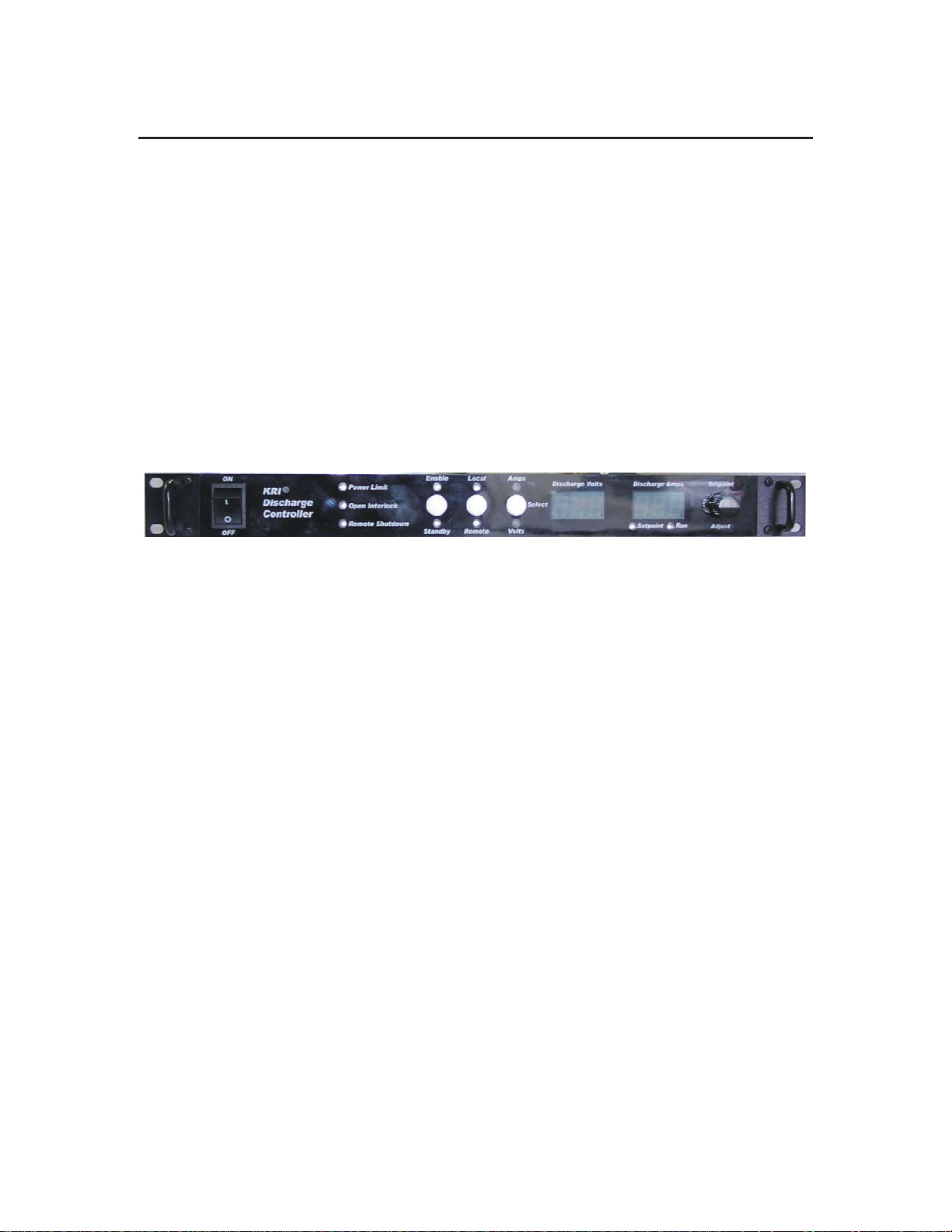
2.3.1 Front Panel ..................................................................................... 2-1
2.3.2 Rear Panel ..................................................................................... 2-2
2.4 Installation .............................................................................................. 2-2
2.4.1 Mounting ........................................................................................ 2-2
2.4.2 Cooling ........................................................................................... 2-2
2.4.3 Electrical-connections to ion source and discharge power supply . 2-3
2.4.4 Electrical-AC input .......................................................................... 2-3
3 OPERATION .................................................................................................. 3-1
3.1 Local Mode ............................................................................................. 3-1
3.2 Remote Mode RS-232 ............................................................................ 3-2
3.2.1 Direct RS-232 connection from computer to discharge ................ 3-3
power supply .................................................................................. 3-3
3.2.1.1 Software ................................................................................ 3-3
3.2.2 Communications settings ............................................................... 3-3
3.2.3 Commands ..................................................................................... 3-3
3.2.4 Operational sequence .................................................................... 3-5
3.3.1 ANALOG Input/Output ................................................................... 3-7
4 DIAGNOSTICS .............................................................................................. 4-1
4.1 General ................................................................................................... 4-1
4.2 Diagnostic Table ................................................................................... 4-1
5 LIMITED WARRANTY ................................................................................... 5-1
6 SERVICE AND TECHNICAL INFORMATION ............................................... 6-1

ii CONTENTS
_______________________________________________________________________
Copyright © 2011 by Kaufman & Robinson, Inc., 1330 Blue Spruce Drive, Fort Collins, CO 80524
Tel: 970-495-0187, Fax: 970-484-9350, Internet: www.ionsources.com
DISCHARGE POWER SUPPLY MANUAL
MODEL DC3005, MODEL 30010, MODEL 15012
Figures
Fig. 2-1 Discharge Power Supply front panel. .................................................. 2-4
Fig. 2-2 Discharge Power Supply rear panel. .................................................. 2-5
Tables
Table 1-1 Maximum Power, Voltage, and Output ............................................. 1-3
Table 2-1 Inventory List. ................................................................................... 2-1
Table 3-4 Analog connections. .......................................................................... 3-7
Table 3-4 Interlock connections. ....................................................................... 3-9
Table 4-1 Help codes and error messages for the Discharge Power Supply. .. 4-1

GENERALINFORMATION 1-1
_______________________________________________________________________
Copyright © 2011 by Kaufman & Robinson, Inc., 1330 Blue Spruce Drive, Fort Collins, CO 80524
Tel: 970-495-0187, Fax: 970-484-9350, Internet: www.ionsources.com
DISCHARGE POWER SUPPLY MANUAL
MODEL DC3005, MODEL 30010, MODEL 15012
1 GENERAL INFORMATION
1.1 Introduction
The Kaufman & Robinson, Inc. Discharge Power Supply is designed for use with
a Kaufman & Robinson Ion Source. The intended use of this Power Supply is to
provide DC voltage and current to the Ion Source Anode for ion production. The
purpose of this publication is to provide the user with information regarding safe
operation and use of this device. This power Supply has numerous features
built in. Features designed into this unit follow:
• Both Current and Voltage control adjustment.
• Local mode operation.
• Remote mode operation using analog I/O through DB25 connector.
• Remote programming and monitoring via RS232 interface.
• RS485 High Speed Serial link for proprietary communications with KRI
Controllers.
• "Fan on Demand" cooling with thermal shutdown protection.
• Front panel selectivity for local/remote mode.
1.2 Safety
Caution: Only technically qualified personnel should install, maintain, and
troubleshoot the equipment described herein.
Lethal voltages and currents can be developed within the Power Supply,
therefore, the Power Supply chassis should not be opened. Removal of
the Power Supply cover will void all warranties.
The Discharge Power Supply must be installed in a grounded 19-inch (483
mm) rack mount cabinet before operation.
The following safety procedures must be followed for safety purposes:
• Do not remove covers.
• Proper grounding of the chassis is required.
• Use caution when making input power connections.
• Do not remove warning labels from Power Supply.
• Do not use the Power Supply in a method not described in this publication
without consult and approval by KRI engineering.
• Disconnect the power cord from the back of the Discharge Power Supply
prior to making any modifications to the power supply inputs or outputs.
• The Discharge Power Supply should only be serviced by Kaufman & Rob-

1-2 GENERAL INFORMATION
_______________________________________________________________________
Copyright © 2011 by Kaufman & Robinson, Inc., 1330 Blue Spruce Drive, Fort Collins, CO 80524
Tel: 970-495-0187, Fax: 970-484-9350, Internet: www.ionsources.com
DISCHARGE POWER SUPPLY MANUAL
MODEL DC3005, MODEL 30010, MODEL 15012
inson, Inc.
1.3 Specifications
The following specifications pertain to the Kaufman & Robinson, Inc., Discharge
Power Supply, Models DC30010, DC3005, and DC15012
1.3.1 Dimensions
The Power Supply is designed to be mounted in a standard 19-inch (48.3 cm)
rack mount cabinet. The height of this Power Supply is 1.75 inches (4.45 cm)
and its depth is approximately 21 inches (53.3 cm).
1.3.2 Weight
The weight of this unit is 7.27 kg (16 pounds).
1.3.3 AC Input
The input voltage for the Discharge Power Supply is 85-275 volts ac single
phase at 50-60 Hz. The maximum input current to the unit is electronically
limited to 28 amps RMS. Operation at lower line voltages may be limited by
outlet capacity and/or circuit breakers.
1.3.4 DC Output
The maximum output for the DC30010 model of this Power Supply is 300
VDC and 10 amps. Operation at this level is limited by thermal protection.
Continuous duty operation is specified at 2000 watts up to 40˚C ambient air
temperature.
The maximum output for the DC3005 model of this Power Supply is 300
VDC and 5 amps. Operation at this level is limited by thermal protection.
Continuous duty operation is specified at 1500 watts up to 40˚C ambient air
temperature.
The maximum output for the DC15012 model of this Power Supply is 150
VDC and 12 amps. Operation at this level is limited by thermal protection.
Continuous duty operation is specified at the maximum 2000 watts up to
40˚C ambient air temperature.

GENERALINFORMATION 1-3
_______________________________________________________________________
Copyright © 2011 by Kaufman & Robinson, Inc., 1330 Blue Spruce Drive, Fort Collins, CO 80524
Tel: 970-495-0187, Fax: 970-484-9350, Internet: www.ionsources.com
DISCHARGE POWER SUPPLY MANUAL
MODEL DC3005, MODEL 30010, MODEL 15012
Table 1-1 Maximum Power, Voltage, and Output
Model Maximum
Power
Maximum
Voltage
Maximum
Current
3005 1500 W 300 V 5 A
30010 2000 W 300 V 10 A
15015 2000 W 150 V 15 A

INSPECTIONANDINSTALLATION 2-1
_______________________________________________________________________
Copyright © 2011 by Kaufman & Robinson, Inc., 1330 Blue Spruce Drive, Fort Collins, CO 80524
Tel: 970-495-0187, Fax: 970-484-9350, Internet: www.ionsources.com
DISCHARGE POWER SUPPLY MANUAL
MODEL DC3005, MODEL 30010, MODEL 15012
2 INSPECTION AND INSTALLATION
This section describes how to install the Kaufman & Robinson, Inc., KRI® Dis-
charge Power Supply which has been designed for operation of a KRI Ion Source.
Unpacking and inspection, physical description, hardware inventories and installa-
tion information is provided to assist in facilitating a successful installation.
2.1 Unpacking and Inspection
Prior to shipment, the Power Supply was inspected and tested and has been
shipped free of defects. As soon as the Power Supply has been completely
removed from all packing materials a visual inspection should be made to de-
termine if there has been any damage to the products during shipment. If any
damage has occurred contact Kaufman & Robinson, Inc., in addition to the ship-
ping company to report any damage, see Warranty section 5. Retain packaging
materials for shipment of the Power Supply. Inventory the contents shipped to
determine completeness of the order.
2.2 Inventory
The following items are shipped with each Power Supply:
Table 2-1 Inventory List.
Quantity Desciption Part Number
1 Discharge Power Supply DC30010/DC3005/
DC15012
1 Power Discharge Supply Cable CBL-A07-PWR-HF-EH
1 Atmosphere Discharge Cable CBL-A04-ATM-HF-EH
1 Discharge Power Supply Manual
2.3 Physical Description
2.3.1 Front Panel
Figure 2-1 shows the front panel of this Power Supply. The Power Supply
has one power switch located on the front panel. The three white buttons
on the front panel are used for manual control of the power supply. The
button switch on the left allows the unit to be placed in an active (enabled)
or inactive (standby) mode. The front panel displays are still active in the
STANDBY mode. The middle button switch selects if the front panel (Local)
or rear panel (Remote) control of the VOLTAGE, and CURRENT. The rear
panel (Remote) includes both analog and RS-232 interface. The right button

2-2 INSPECTION AND INSTALLATION
_______________________________________________________________________
Copyright © 2011 by Kaufman & Robinson, Inc., 1330 Blue Spruce Drive, Fort Collins, CO 80524
Tel: 970-495-0187, Fax: 970-484-9350, Internet: www.ionsources.com
DISCHARGE POWER SUPPLY MANUAL
MODEL DC3005, MODEL 30010, MODEL 15012
selects between the output VOLTAGE, or CURRENT adjustment for the far
right ecoder knob. The left display shows the Discharge voltage setpoint or
readback in volts. The right display shows the Discharge current setpoint or
readback in amps. The Discharge voltage or current is adjustable using the
adjust knob on the front panel. This knob will also adjust the setpoint when
the unit is in Standby mode.
Three indicator lights are located between the power switch and the Enable/
Standby button. The top light indicates if the power limit is being exceeded.
The middle light indicates remote operated interlock is open. And the bottom
light indicates the unit is shutdown in remote mode.
2.3.2 Rear Panel
Figure 2-2 shows the back panel of the Discharge Power Supply. An RS-232
connection is provided on the back panel of this Power Supply for remote
operation. RS-232 connection at the back panel utilizes a DB-9 connector.
The RS-485 is for KRI autocontroller.
A ground stud is provided on the rear panel of this unit for grounding the
chassis of the Power Supply.
Analog connections, utilizing DB-25 female connectors, are provided on the
back panel of this controller for remote operation.
2.4 Installation
2.4.1 Mounting
The Power Supply is designed to be mounted in a standard 19-inch (483
mm) rack mount cabinet. The height of this Power Supply is 1.75 inches (45
mm) and the depth of the unit is approximately 21 inches (533 mm). When
installing the Discharge Power Supply into the cabinet refer to the Ion Source
Controller Manual for installation orientation relative to the other ion source
Power Supplies. Install the Power Supply in the rack mount cabinet prior to
making any electrical connections.
2.4.2 Cooling
This Power Supply is forced air cooled with the airflow entering and exiting
through the back panel of the chassis. Ensure that there are no obstructions
in the rack mount cabinet that will restrict the airflow.

INSPECTIONAND INSTALLATION 2-3
_______________________________________________________________________
Copyright © 2011 by Kaufman & Robinson, Inc., 1330 Blue Spruce Drive, Fort Collins, CO 80524
Tel: 970-495-0187, Fax: 970-484-9350, Internet: www.ionsources.com
DISCHARGE POWER SUPPLY MANUAL
MODEL DC3005, MODEL 30010, MODEL 15012
2.4.3 Electrical-connections to ion source and discharge power supply
Located on the back panel of the Power Supply are two sections of three con-
nectors each for connecting the Discharge Power Supply directly to the ion
source or through a KRI Filament Power Supply. Each terminal is capable of
the full output of the Discharge Power Supply. Multiple outputs are provided
to allow multiple supplies to share connections.
If the Discharge Power Supply was purchased with an Ion Source and Fila-
ment Power Supply, interconnecting cables are provided. Information regard-
ing installation of these connecting cables can be found in the “Ion Source
Filament Cathode Version Controller Manual”.
If the Discharge Power Supply was purchased as a stand alone unit contact
Kaufman & Robinson, Inc. for cabling requirements.
2.4.4 Electrical-AC input
The Power Supply has been designed for 85-285 volts AC input voltage, 50-
60 Hz, single-phase with a maximum current of 28 amps at the lowest line
voltage. A power supply cable has been included with the Power Supply.
This cable has a female plug at one end that corresponds to the male socket
at the rear panel of the Power Supply. The opposite end of this cable has
been intentionally left bare so that the cable may be installed to facility re-
quirements. Electrical connection made from the Discharge Supply Cable to
the AC voltage within the facility should only be made by qualified personnel.

2-4 INSPECTION AND INSTALLATION
_______________________________________________________________________
Copyright © 2011 by Kaufman & Robinson, Inc., 1330 Blue Spruce Drive, Fort Collins, CO 80524
Tel: 970-495-0187, Fax: 970-484-9350, Internet: www.ionsources.com
DISCHARGE POWER SUPPLY MANUAL
MODEL DC3005, MODEL 30010, MODEL 15012
,163(&7,21$1',167$//$7,21
Fig. 2-1 Discharge Power Supply front panel.

INSPECTIONANDINSTALLATION 2-5
_______________________________________________________________________
Copyright © 2011 by Kaufman & Robinson, Inc., 1330 Blue Spruce Drive, Fort Collins, CO 80524
Tel: 970-495-0187, Fax: 970-484-9350, Internet: www.ionsources.com
DISCHARGE POWER SUPPLY MANUAL
MODEL DC3005, MODEL 30010, MODEL 15012
,163(&7,21$1',167$//$7,21
Input
Power
RS-323
Remote
RS-485
Remote
Analog
Remote
Air vents
Ground
Te rm i na l
Positive
Te rm i na l
Negative
Te rm i na l
Interlock
Fig. 2-2 Discharge Power Supply rear panel.

OPERATION 3-1
3 OPERATION
The Discharge Power Supply can be operated in Local and Remote modes. Mode
selection between Local and Remote modes is controlled using a Momentary Push
Button located on the front panel of the Power Supply.
The following information is provided for operation of the Discharge Power Supply.
3.1 Local Mode
Operation of the Discharge Power Supply in Local mode requires the mode in-
dicator LED, located on the front panel of the Power Supply, to be set to Local.
This allows the user to adjust the output for the Discharge Supply using the knob
on the front panel. Information regarding operation of this Power Supply with the
End Hall Ion Source can be found in the End Hall Ion Source Manual, included
in the End Hall Documentation package.
ON/OFF Switch – Supplies power to the Power Supply.
When switched to the ON position, the Power Supply may be in either Remote
or Local control depending on the last operation.
If the last operation was with Local control, then the Power Supply will be in Lo-
cal when switched ON. In this case the supply will be in Standby with the Dis-
charge Amps and Volts Setpoints displayed. The Setpoints that are displayed
will be the last setpoints used before the supply was switched OFF.
If the last operation was with Remote control, then the Power Supply will be in
Remote when switched ON. In this case the supply will respond to the remote
commands in effect when switched ON.
Power Limit indicator – Indicates that the output power exceeds the setup limits.
Open Interlock indicator – Indicates that the interlock connection located on the
back panel is open.
Remote Shutdown indicator – Indicates that remote shutdown has been com-
manded through the analog or RS-232 remote interface.
Enable/Standby Push Button – Enables or disables the output.
When Standby is selected, the Displays indicate Setpoints. When Enabled is
selected, the Power Supply regulates the Discharge Amps/Volts to maintain the
Setpoint Limits.
Note: The setpoints are output "limits" and only one can be "regulated" at any
_______________________________________________________________________
Copyright © 2011 by Kaufman & Robinson, Inc., 1330 Blue Spruce Drive, Fort Collins, CO 80524
Tel: 970-495-0187, Fax: 970-484-9350, Internet: www.ionsources.com
DISCHARGE POWER SUPPLY MANUAL
MODEL DC3005, MODEL 30010, MODEL 15012

3-2 OPERATION
_______________________________________________________________________
Copyright © 2011 by Kaufman & Robinson, Inc., 1330 Blue Spruce Drive, Fort Collins, CO 80524
Tel: 970-495-0187, Fax: 970-484-9350, Internet: www.ionsources.com
DISCHARGE POWER SUPPLY MANUAL
MODEL DC3005, MODEL 30010, MODEL 15012
given time. The load will determine the other. Example: If the Discharge set-
points are 5 amps and 200 volts and the load is 25 Ohms then the output will
be limited to 5 amps and the output voltage will be 5x25 = 125 volts according
to Ohms law (V = IxR). If the Load resistance is 50 Ohms then the output will
be limited to 200 volts and the current will be 200/50 = 4 amps. The Discharge
control offers automatic and extremely fast crossover between Voltage and Cur-
rent regulation.
Local/Remote switch – Selects Local (front panel) or Remote (analog or RS-
232) control.
Amps/Volts Select – Selects which parameter is being adjusted by the setpoint
adjust encoder knob as indicated by the amps or volts light.
Discharge Volts display – Displays the measured discharge voltage in volts.
Discharge Amps display – Displays the discharge current setpoint and run val-
ues in amps. When the yellow setpoint indicator below the display is illuminated,
the setpoint value is displayed. When the green run indicator is illuminated, the
run value is displayed.
Setpoint indicator – Indicates when the setpoints are being displayed on the
Digital Displays. When the yellow setpoint indicator below the display is illumi-
nated, the setpoint value is displayed. When the green run indicator is illumi-
nated, the run value is displayed.
Run indicator – Indicates when the running values are being displayed on the
Digital Displays.
Setpoint Adjust knob – Adjusts the Voltage and Current setpoints when in local
mode.
3.2 Remote Mode RS-232
Operation of the Discharge Power Supply in Remote mode requires the mode
selector switch, located on the front panel of the Power Supply, to be switched
to Remote.
The Discharge Power Supply can be operated from a host computer using an
RS-232 port on the computer. Connection from the computer is made from a
serial port on the computer to the serial port on the Discharge Power Supply,
labeled, “RS-232”, “Discharge”. This approach uses an RS-232 straight through
cable that connects to a DB-9 male connector. This approach allows the user to

OPERATION 3-3
_______________________________________________________________________
Copyright © 2011 by Kaufman & Robinson, Inc., 1330 Blue Spruce Drive, Fort Collins, CO 80524
Tel: 970-495-0187, Fax: 970-484-9350, Internet: www.ionsources.com
DISCHARGE POWER SUPPLY MANUAL
MODEL DC3005, MODEL 30010, MODEL 15012
control the Discharge Power Supply only.
3.2.1 Direct RS-232 connection from computer to discharge
power supply
The Discharge Power Supply can be operated from a host computer using
an RS-232 port on the computer. Connection from the computer is made
from a serial port on the computer to the serial port on the Discharge Power
Supply, labeled, “RS-232”. This approach uses an RS-232 straight through
cable that connects to a DB-9 male connector. This approach allows the user
to control the Discharge Power Supply only.
3.2.1.1 Software
Software control of the Discharge Power Supply can be accomplished
using a variety of methods. Some type of terminal or communications
program, or programming can be used for controlling this unit. Some
examples of programs that can be used are Hyper Terminal provided
with Microsoft® Windows® systems and LabviewTM by National
InstrumentsTM. Consult the user guide for installation and operation of
the software that you plan on using for use of that program.
3.2.2 Communications settings
Operation of the Discharge Power Supply using a Serial connection requires
the following settings within the terminal or communications program:
• Set communications port to available Comm number.
• Baud Rate Selectable = 1200, 2400, 4800, 9600, 19200, 38400, 57600,
and 115,200 Baud. Note: the default value is 9600. Contact KRI® for
other baud rates.
• Data Bits = 8.
• Parity = None.
• Stop Bits = 1.
3.2.3 Commands
The following ascii commands are specific for the Discharge Power Supply.
These commands allow the user to adjust the setpoints on the Discharge
Power Supply and monitor the output voltages and currents.
• VAxxxx Sends a Current setpoint to the Discharge Power Supply.
Note: xxxx is a decimal value from 0-4095. VA0 is the minimum or

3-4 OPERATION
_______________________________________________________________________
Copyright © 2011 by Kaufman & Robinson, Inc., 1330 Blue Spruce Drive, Fort Collins, CO 80524
Tel: 970-495-0187, Fax: 970-484-9350, Internet: www.ionsources.com
DISCHARGE POWER SUPPLY MANUAL
MODEL DC3005, MODEL 30010, MODEL 15012
zero output, it also puts the unit in standby mode, while VA4095 is ..
maximum output.
• VBxxxx Sends a Voltage setpoint to the Discharge Power Supply. .
Note: xxxx is a decimal value from 0-4095. VB0 is the minimum or .
zero output, it also puts the unit in standby mode, while VB4095 is maxi-
mum output.
• *IDN? Identification query. Returns the product identifier code.
• RD0 Returns a decimal number 0-4095 for conversion to the correspond-
ing output current.
• RD1 Returns a decimal number 0-4095 for conversion to the correspond-
ing output voltage.
• RD? Returns both RD parameters with one request.
· *RST Reset. Puts the unit into standby and resets the output to zero.
·*TST? Test. Returns a 0 (zero) if the unit is functioning normally, or a
number that corresponds to the front panel help codes as described in
diagnostics section 4.
·MEASure:CURRent? or MEAS:CURR? Measure current query. Returns
the DC output current in amps with three decimal places.
·MEASure:VOLTage? or MEAS:VOLT? Measure voltage query. Returns
the DC output voltage in volts with three decimal places
·SOURce:CURRent or SOUR:CURR Input the operating current. The
desired operating current in amps following either the long or short form
of the command. A space can be inserted after the command, or the
space can be omitted. The level of current must be within the range for
the power supply. Up to three decimal places may be used to input the
current, but these decimal places do not have to be specified. The deci-
mal point is also not required if there are no significant decimal places. In
the case of the bias and keeper supply, if this command is anything other
than zero, it also enables the supply. Conversely, a command of zero will
put the power supply into standby for the bias and keeper. The discharge
supply requires that both the SOURce:CURRent and SOURce:VOLTage
be non zero to enable the power supply.

OPERATION 3-5
_______________________________________________________________________
Copyright © 2011 by Kaufman & Robinson, Inc., 1330 Blue Spruce Drive, Fort Collins, CO 80524
Tel: 970-495-0187, Fax: 970-484-9350, Internet: www.ionsources.com
DISCHARGE POWER SUPPLY MANUAL
MODEL DC3005, MODEL 30010, MODEL 15012
·SOURce:VOLTage or SOUR:VOLT Input the operating voltage. The de-
sired operating voltage in volts follow either the long or short form of the
command. A space can be inserted after the command, or the space can
be omitted. The level of voltage must be within the range for the power
supply. Up to three decimal places may be used to input the voltage, but
these decimal places do not have to be specified. The decimal point is
also not required if there are no significant decimal places. The discharge
supply requires that both the SOURce:CURRent and SOURce:VOLTage
be non zero to enable the power supply. A current or voltage command of
zero will put the discharge power supply into standby.
All the commands and queries must be followed by a carriage return.
NOTE: If either VX command is zero the unit will go to standby.
3.2.4 Operational sequence
Using a terminal program configured for the communications settings previ-
ously mentioned, input the following commands in the defined sequence.
User Inputs are shown with quotations to designate the exact command the
user must input, the quotation marks should not be input into the terminal
program.
• During power up of the Discharge Power Supply set the output to zero
current output for safety. Input “VA0” then press the enter key.
• Determine the Discharge output current required. Using the following
formula, determine the decimal value required for input into the terminal
program corresponding to the required Discharge current :
Input value = required discharge current = (0 to maximum amps) x
4095/10.
Example: A value of 5 amps of discharge current is desired. Using the
above formula, 5 X 4095/10 = 2047 for model DC30010.
• Determine the Discharge output Voltage required. Using the following
formula, determine the decimal value required for input into the terminal
program corresponding to the required Discharge voltage :
Input value = required discharge voltage = (0 to maximum volts) x
4095/300.
Example: A value of 200 volts of discharge voltage is desired. . Using

3-6 OPERATION
_______________________________________________________________________
Copyright © 2011 by Kaufman & Robinson, Inc., 1330 Blue Spruce Drive, Fort Collins, CO 80524
Tel: 970-495-0187, Fax: 970-484-9350, Internet: www.ionsources.com
DISCHARGE POWER SUPPLY MANUAL
MODEL DC3005, MODEL 30010, MODEL 15012
the above formula, 200 X 4095/300 = 2730 for model with a maximum
voltage of 300 volts.
• Input “VAxxxx” then press the enter key. Note: xxxx corresponds to a
decimal number from 0-4095. For the example above, input “VA2047”
into the terminal program and then press the enter key to set the output to
half the maximum current in amps.
• Input “VBxxxx” then press the enter key. Note: xxxx corresponds to a
decimal number from 0-4095. For the example above, input “VB2730”
into the terminal program and then press the enter key to set the output to
two third (2/3) the maximum voltage in volts.
• Powering down the Discharge Power Supply should be done by resetting
the output current to zero, this is done by inputting the following command
into the terminal program: Input “VA0” then press the enter key. The out-
put will drop to zero and the Standby LED will be illuminated.
• Output Current: Monitoring of the output current can be done using the
following command: Input “RD0” then press the enter key. This reads
a decimal number from 0-4095 that can then be converted to the cor-
responding output current. To convert the decimal number to the output
current, divide the returned value by 4095 and multiply by the maximum
current.
Returned value/4095 X maximum current.
Example: The command RD0 was sent to the Discharge Power
Supply and the value 2048 was returned from the terminal program.
To convert this value to the output current take 2048 and divide by
4095, times 10 equals 5, this would give a output current of 5 amps for
model DC30010.
• Output Voltage: Monitoring of the output voltage can be done using the
following command: Input “RD1” then press the enter key. This reads
a decimal number from 0-4095 that can then be converted to the corre-
sponding cathode current. To convert the decimal number to the output
voltage divide the returned value by 4095 and multiply by the maximum
voltage of that model power supply.
Returned value/4095 X maximum output voltage.
Example: The command RD1 was sent to the Discharge Power

OPERATION 3-7
_______________________________________________________________________
Copyright © 2011 by Kaufman & Robinson, Inc., 1330 Blue Spruce Drive, Fort Collins, CO 80524
Tel: 970-495-0187, Fax: 970-484-9350, Internet: www.ionsources.com
DISCHARGE POWER SUPPLY MANUAL
MODEL DC3005, MODEL 30010, MODEL 15012
Supply and the value of 2048 was returned from the terminal program.
To convert this value to the output voltage, divide 2048 by 4095 and
multiply by 300 volts for model DC30010 power supply.
3.3 Remote Mode Analog
The Discharge Power Supply can be operated using analog.
3.3.1 ANALOG Input/Output
The Discharge Power Supply can be remotely controlled using a 0-5 volt DC
analog interface. The analog remote uses 0-5 volt signals for controlling and
monitoring the Power Supply. There is one 25 pin female D connector la-
beled ANALOG on the back of the Power Supply for connection to the analog
interface. The pin descriptions for the interface are given below in table 1.
There is a button on the front panel that can be used to switch from remote
to local control. There is also a two pin Molex connector on the back panel
labeled INTERLOCK. The pin descriptions for the interlock are also given
below in table 3-4.1.
Table 3-4 Analog connections.
Pin
Number
Description
1 Output Enable – Output is enabled when 5 volts is applied.
Output goes to standby mode when 0 volts is applied or when
no contact is made. Enable and Standby are indicated on the
front panel.
2 Remote Shutdown, Active High – Output is disabled when 5
volts is applied. The shutdown is deactivated when 0 volts is
applied or no contact is made. Remote Shutdown is indicated
on the front panel when activated.
3 Common.
4 Remote Local Indicator Output – 0 volts = Remote, 5 volts =
Local (5 kΩsource impedance). Also available on pin 20.
5 No Contact.
6 Common.
7 Discharge Current Monitor – Outputs 0 to 5 volts for 0 to maxi-
mum amps of discharge current.
8 No contact

3-8 OPERATION
_______________________________________________________________________
Copyright © 2011 by Kaufman & Robinson, Inc., 1330 Blue Spruce Drive, Fort Collins, CO 80524
Tel: 970-495-0187, Fax: 970-484-9350, Internet: www.ionsources.com
DISCHARGE POWER SUPPLY MANUAL
MODEL DC3005, MODEL 30010, MODEL 15012
Pin
Number
Description
9 Discharge Voltage Setpoint – Input 0 to 5 volts for 0 to maxi-
mum discharge volts.
10 Discharge Current Setpoint – Input 0 to 5 volts for 0 to maxi-
mum amps of discharge current. Also available at pin 22.
11 Common
12 Common.
13 Auxiliary +5 volts DC, 200 mA max. Also available at pin 15 and
25.
14 Remote Shutdown, Active Low – Output is disabled when con-
nected to common. The shutdown is deactivated when 5 volts
is applied or no contact is made. Remote shutdown is indicated
on the front panel when activated.
15 Auxiliary +5 volts DC, 200 mA max. Also available at pin 13 and
25.
16 Common
17 Common
18 Over Temperature Output – A 5 volt output indicates over tem-
perature (5 kΩsource impedance).
19 Discharge Voltage Monitor – Outputs 0 to 5 volts for 0 to maxi-
mum volts discharge voltage.
20 Remote Local Indicator Output – 0 volts = Remote, 5 volts =
Local (5 kΩsource impedance). Also available on pin 4.
21 Common
22 Discharge Current Setpoint – Input 0 to 5 volts for 0 to maxi-
mum amps of discharge current. Also available at pin 10.
23 Regulation Mode – A 5 volt output indicates current regulation.
A 0 volt output indicates voltage regulation. 5 kΩsource imped-
ance.
24 Common
25 +Auxiliary + 5 volts DC, 200 mA max. Also available at pin 13.

OPERATION 3-9
_______________________________________________________________________
Copyright © 2011 by Kaufman & Robinson, Inc., 1330 Blue Spruce Drive, Fort Collins, CO 80524
Tel: 970-495-0187, Fax: 970-484-9350, Internet: www.ionsources.com
DISCHARGE POWER SUPPLY MANUAL
MODEL DC3005, MODEL 30010, MODEL 15012
Table 3-4 Interlock connections.
Pin
Number
Description
1 Active Low Interlock – Connect to common (Interlock pin 2) to
enable the Discharge Power Supply.
2 Interlock Return – Common.
This manual suits for next models
2
Table of contents
Other Kaufman & Robinson Power Supply manuals