Kawneer reserves the right to change conguration without prior notice when deemed
necessary for product improvement.
© Kawneer Company, Inc., 2013
Laws and building and safety codes governing the design and use of glazed
entrance, window, and curtain wall products vary widely. Kawneer does not control
the selection of product congurations, operating hardware, or glazing materials,
and assumes no responsibility therefor.
2
kawneer.com
EC 97904-076
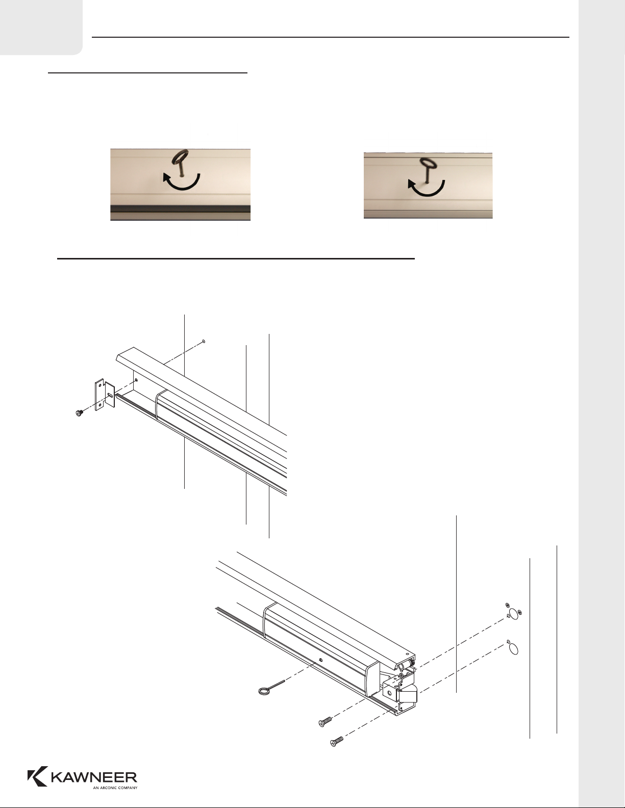
Kawneer 1786 Rim Exit Device
INSTALLATION INSTRUCTIONS
APRIL, 2018
038311EN
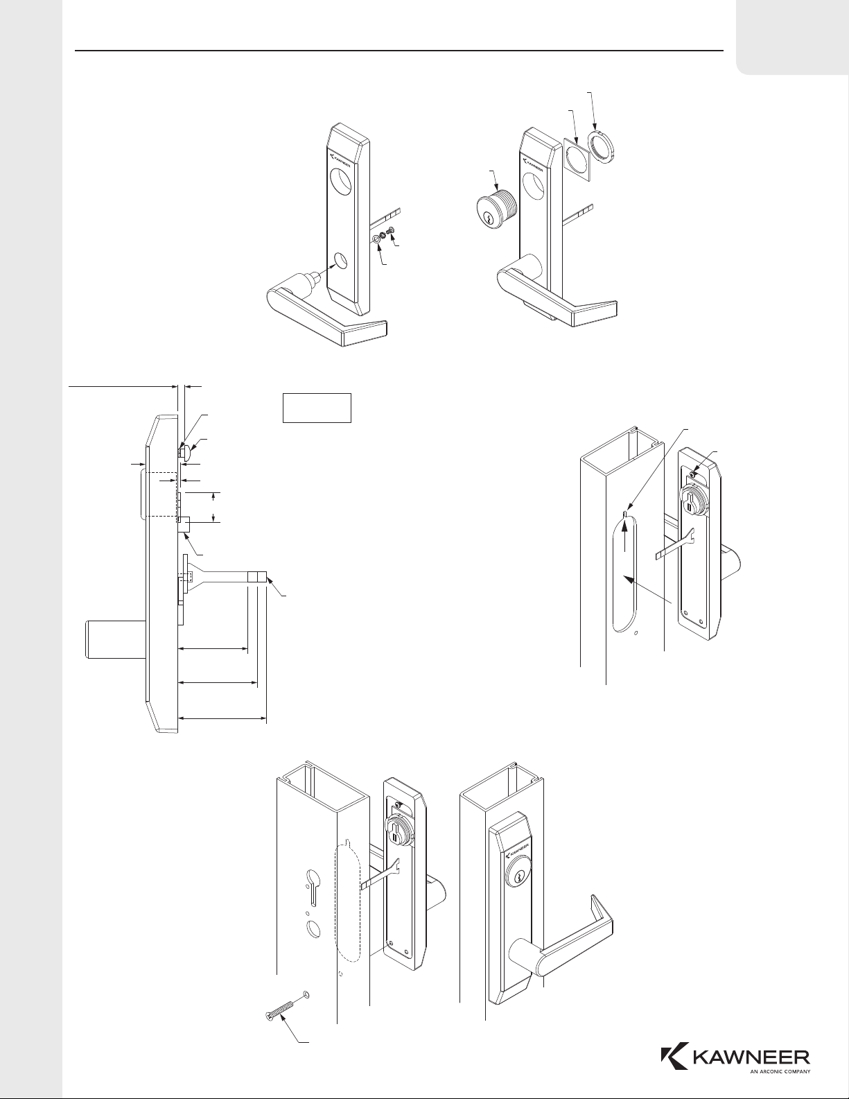
OPTIONAL TRIM
1786 RIM EXIT DEVICE LEVER HANDLE TRIM ASSEMBLY/INSTALLATION INSTRUCTIONS:
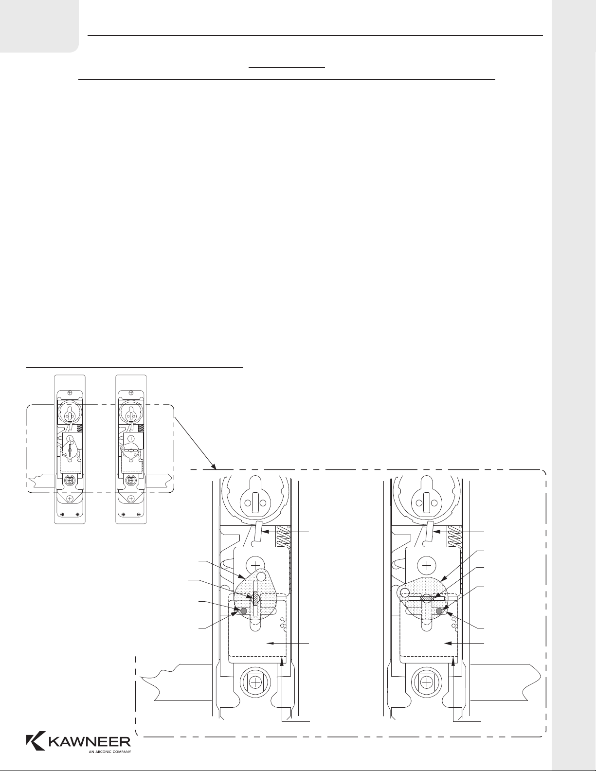
1) Trim mounting base is handed to accommodate a left or right handle application. To construct a left hand (LH) lever handle, rotate cam clockwise
making sure the cam pin aligns with slot on left side of cam guide. (See Illustration below) Once the pin is in position, slightly push up and hold
cam guide and cam while inserting lever handle rmly into place within the trim mounting base. The tail piece will now be oriented in the vertical
position.
2) To construct a right hand (RH) lever handle, rotate cam counter clockwise making sure the cam pin aligns with slot on right side of cam guide. (See
Illustration below) Once the pin is in position, slightly push up and hold cam guide and cam while inserting lever handle rmly into place within the
trim mounting base. The tail piece will now be oriented in the vertical position.
3) Assemble (1) 1/4" -20 x 1/2" Phillips pan head fastener with (1) steel at washer and (1) lock washer to secure lever handle to trim mounting base.
4) Insert 15/16" key cylinder (dummy cylinder on inactive door leaf) into top hole of trim mounting base. Align mounting guide plate to key cylinder and
secure with retaining ring.
5) When using a key cylinder longer than 15/16", cylinder rings will be required to maintain a 1/8" cylinder projection. When using a dummy cylinder
on inactive door leafs, place the lock arm switch in a lock position to disable the lever handle function.
6) Before installation of trim mounting base, cut break-away tail piece to the correct length. (see illustration)ation.
7) Find (1) 1/4"-20 x 3/4" Phillips pan head fastener and apply several drops of thread locker liquid to lower threads. Install Phillips pan head fastener
into trim mounting base and set to accommodate a 1/8" (Standard/Thermal door) or 3/16" (Heavy Wall) wall thickness. (Fastener may require
additional adjustment to ensure that trim mounting base is fully secured into position.)
8) On exterior side of door stile, position lever handle trim assemble into cutout, just below the fastener slot cutout. Being careful not to scratch the
exposed nish surface, slide lever handle trim assemble up to engage fastener into slot.
9) On interior side of door stile, install (1) fastener (see below) through door to secure lever handle trim assembly in position.
(1) #10-24 x 2 1/4" FHMS for Standard 1-3/4" doors
(1) #10-24 x 2-1/2" FHMS for Heavy Wall 2" doors
(1) #10-24 x 2-3/4" FHMS for Thermal 2-1/4" doors
10) Lever handle trim assemble should be tightly secured to ensure that hardware is placed square upon door stile and cannot be moved.
11) Upon completion, insert cylinder key and turn clockwise to unlock, then counter- clockwise to lock.
12) Install rim exit device.
1786 RIM EXIT DEVICE TRIM HANDING GUIDE:
Cam Lift Pin
Cam
Cam
Guide
Lever
(LH)
Lever Handle
(Shown LH Single
Active Pair)
Lever Handle
(Shown RH Single
Inactive Pair) Cam
Cam Lift Pin
Cam
Guide
Tail Piece
(Vertically)
Left Slot
Lever
(RH)
Lock Arm Switch Lock Arm Switch
Right Slot
Tail Piece
(Horizontally)
Push Up and
Hold Cam Guide
Push Up and
Hold Cam Guide