manuals.online logo
Brands
  1. Home
  2. •
  3. Brands
  4. •
  5. Kaysun
  6. •
  7. Air Conditioner
  8. •
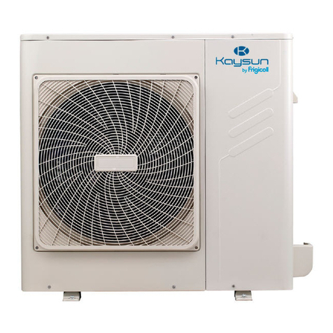
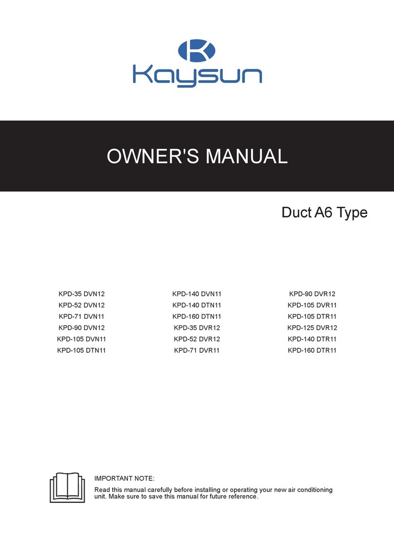
  9. Kaysun KMF-400 DN3 User manual

Kaysun KMF-400 DN3 User manual

Thank you very much for purchasing our air conditioner.
Before using your air conditioner, please read this manual carefully and keep it for future
reference.
INSTALLATION MANUAL
Amazon Unitario
KMF-400 DN3 KMF-450 DN3
CONTENTS
PAGE
WARNING
Ask an authorized dealer or qualified installation professional to
install/maintain the air conditioner.
Inappropriate installation may result in water leakage,electric shock
or fire.
Turn off the main power supply switch or breaker before
attempting any electrical work.
Make sure all power switches are off.Failure to do so may cause
electric shock.
Connect the connecting cable correctly.
If the connecting cable is connected in a wrong way, electric parts
may be damaged.
When moving the air conditioner for the installation into another
place, be very careful not to enter any gaseous matter other
than the specified refrigerant into the refrigeration cycle.
If air or any other has is mixed in refrigerant, the gas pressure in the
refrigeration cycle becomes abnormally high and it may resultingly
causes pipe burst and injuries on persons.
Ensure that all Local, National and International regulations
are satisfied.
Do not modify this unit by removing any of the safety guards or
by by-passing any of the safety interlock switches.
Exposure of unit to water or other moisture before installation
may cause a short-circuit of electrical parts.
Do not store it in a wet basement or expose to rain or water.
After unpacking the unit, examine it carefully if there are
possible damage.
Read this ”PRECAUTIONS ” carefully before Installation.
The precautions described below include the important
items regarding safety. Observe them without fail.
After the installation work, perform a trial operation to check
for any problem.
Follow the Owner’s Manual to explain how to use and
maintain the unit to the customer.
Do not install in a place that might increase the vibration of the
unit.
Turn off the main power supply switch (or breaker) before
maintenance the unit .
To avoid personal injury (with sharp edges), be careful when
handling parts.
Ask the customer that the Installation Manual and the Owner’s
Manual should be kept together .
Perform installation work properly according to the Installation
Manual.
Inappropriate installation may result in water leakage, electric shock
or fire.
When the air conditioner is installed in a small room, provide
appropriate measures to ensure that the concentration of
refrigerant leakage occur in the room does not exceed the
critical level.
Install the air conditioner securely in a location where the base
can sustain the weight adequately.
Perform the specified installation work to guard against an
earthquake.
If the air conditioner is not installed appropriately, accidents may
occur due to the falling unit.
If refrigerant gas has leaked during the installation work,
ventilate the room immediately.
If the leaked refrigerant gas comes in contact with fire, noxious gas
may generate.
After the installation work, confirm that refrigerant gas doer not
leak.
CAUTION
New Refrigerant Air Conditioner Installation
THIS AIR CONDITIONER ADOPTS THE NEW HFC REFRIGERANT
(R410A)WHICH DOES NOT DESTROY OZONE LAYER.
The characteristics of R410A refrigerant are; Hydrophilic, oxid-
izing membrane or oil, and its pressure is approx.1.6 times high-
er than that of refrigerant R22.Accompanied with the new refrig-
erant, refrigerating oil has also been changed ,Therefore, during
installation work, be sure that water, dust, former refrigerant, or
refrigerating oil does not enter the refrigerating cycle.
To prevent charging an incorrect refrigerant and refrigerating oil,
the sizes of connecting sections of charging port of the main
unit and installation tools are charged from those for the
conventional refrigerant.
Accordingly the exclusive tools are required for the new
refrigerant (R410A):
For connecting pipes, use new and clean piping designed for
R410A,and please care so that water or dust does not enter.
Moreover, do not use the existing piping because there are
problems with pressure-resistance force and impurity in it.
If refeigerant gas leaks into the room and flows near a fire source,
such as a cooking range, noxious gas might generate.
Electrical work must be performed by a qualified electrician in
accordance with the Installation Manual. Make sure the air
conditioner uses an exclusive power supply.
An insufficient power supply capacity or inappropriate installation
may cause fire.
Use the specified cables for wiring connect the terminals
securely fix. To prevent external forces applied to the terminals
from affecting the terminals.
CAUTION
Do not connect the Appliance from Main Power Supply.
This unit must be connected to the main power supply by
means of a switch with a contact separation of at least 3 mm.
The installation fuse must be used for the power supply line of
this conditioner.
If the supply cord is damaged, it must be replaced by the
manufacturer or its service agent or a similarly qualified person
in order to avoid a hazard.
An all-pole disconnection switch having a contact separation of
at least 3mm in all poles should be connected in fixed wiring.
The appliance shall be installed in accordance with national
wiring regulations.
Be sure to provide grounding.
Do not connect ground wires to gas pipes, water pipes, lightning rods
or ground wires for telephone cables.
Conform to the regulations of the local electric company when
wiring the power supply.
Inappropriate grounding may cause electric shock.
Do not install the air conditioner in a location subject to a risk
of exposure to a combustible gas.
If a combustible gas leaks, and stays around the unit, a fire may occur.
Required tools for installation work
1) Philips screw driver
The temperature of refrigerant circuit will be high, please keep
the interconnection cable away from the copper tube.
The power cord type designation is H05RN-R or above/H07RN-F.
2) Hole core drill(65mm)
3) Spanner
4) Pipe cutter
5) Knife
installation manual
6) Reamer
16) Metal saw
7) Gas leak detector
8) Tape measure
9) Thermometer
10) Mega-tester
11) Electro circuit tester
12) Hexagonal wrench
13) Flare tool
17) Gauge manifold (Charge hose:R410A special requirement)
18) Vacuum pump (Charge hose:R410A special requirement)
19) Torque wrench
1/4(17mm)16N•m (1.6kgf•m)
3/8(22mm)42N•m (4.2kgf•m)
1/2(26mm)55N•m (5.5kgf•m)
5/8(15.9mm)120N•m (12.0kgf•m)
20) Copper pipe gauge adjusting projection margin
21) Vacuum pump adapter
14) Pipe bender
15) Level vial
Please check whether the following fittings are of full scope. If there are some spare fittings , please restore them carefully.
NAME
SHAPE
QUANTITY
1
1. Outdoor unit installation manual
2. Outdoor unit owner’s manual
3. Indoor unit owner’s manual
1
1
1
INSTALLATION FITTINGS
4. Installation Instructions:
Indoor Unit Manifold
5.Straight screwdriver
6.Connection pipe
1
1
7.Curved connection pipe
1
3.4 Vaccumizing
Vaccumizing from both gas and liquid sides after tightness test.
(Pressure of vacuum should be -0.1MPa)
3.1 Unpacking installation
1.After unpacking, check if there’s trasportation injuries. Declare
to the transportation agent immediately in written form.
2.Check if the models, specifications and quantity are conform to
the content in the contract.
3.Keep the operation manual and check the accessories when
unpacking.
3.5 Refrigerant adding
1.Calculating refrigerant adding amount according to the
diameters and length(actual length) of indoor/outdoor unit liquid
side pipes.
2.Mark refrigerant adding amount, pipe diameters of pipe, length
(actual length) and height difference between indoor and
outdoor unit on the usage confirm form of outdoor unit(on
electronic control box plate) in advance, in order to further use.
3.2 Refrigerant pipe
1.Use the central air-conditioner specified refrigerant pipe.
2.Refrigerant pipe with specified diameters and thickness should
be used.
3.Nitrogen blanket protection should be applied when welding
copper pipes. Fill nitrogen of 0.2kgf/cm before welding. Cut off
nitrogen when the copper pipe completely cooled after welding.
4.Heat preservation process should be applied to refrigerant pipe.
5.After installing refrigerant pipe, indoor unit can’t be powered on
before tightness test and vaccumizing.
3.6 Electric wiring
1.Please choose the power supply capacity, diamters of wires
according to the design manual. Power supply cables of
air-conditoner should be thicker than cables used in normal
electric motor.
2.To prevent air-conditioner from malfunctioning, don’t entwine
power supply wires (380V 3N~)and connecting wires of indoor
and outdoor unit(low voltage wires).
3.Power on indoor unit after tightness test and vaccumizing.
4.For function dial code, please refer to dial code instruction
table usage.
3.3 Tightness test
After installing refrigerant pipe, fill 40kgf/cm(3.9MPa)) nitrogen
from both gas and liquid sides to process a 24-hour tightness test.
3.7 Trial running
Trial running can be processed after 12-hour (or above)
preheating of outdoor unit, otherwise it could damage the system.
installation manual
WARNING
Ask an authorized dealer or qualified installation professional to
install maintain the air conditioner.Inappropriate installation may
result in water leakage,electric shock or fire.
Do not expose the unit directly to sunlight and other souces of heat.
Add a cover if necessary to prevent the unit from direct sunlight.
A place that is even and strong enough to bear the weight of the
unit.
Do not install in a place that might increase the vibration of the unit.
Install the unit at a place where noise and hot air couldn’t bother
your neighbour.
Do not install the air conditioner in a location subject to a risk of
exposure to a combustible gas. If a combustible gas leaks, and
stays around the unit, a fire may occur.
Fig.4-2
Remove obstacles around the unit in order to leave enough space
for air circulation.
Install the unit near to the indoor unit as faras possible under
certain installation conditions.
>4000
>1000
>8000
>6000
>400
When installing the outdoor unit in a place that is constantly
exposed to a strong wind such as the upper stairs or rooftop of
a building, use a baffle when necessary.
Install the unit so that its discharge port faces to the wall of the
building. Keep a distance of 4000mm or more between the unit and
the wall surface. Keep strong wind from blowing back inside.
Do not mount the outdooor unit on a wall.
Fig.4-3
strong wind
>400
>600
>4000
4.1 Installation place
Please keep away from the following place, or malfunction of the
machine may be caused:
Fig.4-4
There is combustible gas leakage.
4.2 Handling
There is much oil (including engine oil) ingredient.
There is salty air surrounding(near the coast)
1)Do not unpacking the unit when handling. Use two ropes whose
lengths are more than 8m to handle the unit. Keep balance of the
unit, when lifting stably. Use a padding plate or packing materials
for protection if the package has been destroyed or no package.
2)Keep the unit vertical when moving and handling. If the unit
barycenter is not at the center of the unit, do not lean it more than
30°. Refer to Fig.4-5. Be careful during moving and lifting .
3)Never hold the inlet of the outdoor unit to prevent it from deforming.
4)Do not touch the fan with hands or other objects.
There is caustic gas (the sulfide, for example) existing in the
air (near a hotspring)
A place the heat air expelled out from the outdoor unit can
reach your neighbor’s window.
A place that the noise interferes your neighbors every day life.
A place that is too weak to bear the weight of the unit
Uneven place.
5)Do not lean it more than 45°, and do not lay it sidelong.
Insufficient ventilation place.
Rope
Near a private power station or high Frequency equipment.
Install indoor unit, outdoor unit, power cord and connecting
wire at least 1m away from TV set or radio to prevent noise or
picture interference.
Installation space (Unit:mm), see Fig.4-1,4-2,4-3,4-4 .
Do not unpacking
(Wall or obstacle)
Air inlet
Position of barycenter
>400
Maintain
channel
>600
Air inlet
Make the rope go through the
lifting holes from both right and
left sides in the wooden collet
Air outlet
Fig.4-1
Fig.4-5
installation manual
4.4 Dimension(Unit: mm)
4.3 Outdoor unit basement
1)Advantages of a strong and correct basement :
①Outdoor unit won’t subside
②Outdoor unit won’t generate abnormal noise caused by improper
basement.
2)Basement types
①Steel-frame basement
②Concrete basement(See Fig.4-6 for common practice)
Outdoor unit
Φ10 expansion bolt
Rubber anti-vibration
mounting
Concrete
foundation
C
Solid ground
or roof
Fig.4-7
A
B
505
≥150mm
Fig.4-6
Points of making a basement:
①Host unit basement should be made in strong concrete ground,
See Fig 3.6 for common practice or start after field measurement
②The basement should be completely horizontal and make sure all
the contactors can contact symmetrically.
Fig.4-8
③Ensure the the basement supports the vertical foldings of the front
and back bottom plates directly, since its the actual bearing place.
④Macadam base is unnecessary. But cocrete surface should be
roughed. The proportions used in mixing the concrete should be
cement 1/sand 2/ pebble 4, including Φ10reinforced rebar. Even
the surface of concrete. The edge of the basement should be
chamfered.
⑤Drainage ditch should be arranged around the basement in order
to drainage water around the unit.
⑥Please check endurance of the roof to ensure loading capacity
could bear the weight.
Table 4-1
Size
A
B
C
Model
40kW
45kW
175
225
505
555
1360
1460
4.5 Pipe connection
Gas side
Liquid side
Needle valve(Pressure inspection
and refrigerant adding)
Liquid side pipe
Connecting pipe
(Accessory)
Through-pipe hole
Through-wire hole
Fig.4-9
installation manual
5.2 Pipe types
5.1 Refrigerant pipes
1.Flare
1)Cut the pipe with a knife.(See Fig.5-1)
2)Fit the pipe to the flare of connecting nut(Table 5-1)
Refrigerant settings
Table 5-3
Code
Names
Piping position
Main pipe
Pipe between the outdoor unit and
indoor-side first manifold
L1
Burr
Indoor unit main
pipe
Pipe which doesn’t connect directly with the L2~L5
indoor unit the indoor-side first manifold
Rough
Lean
90
Outdoor unit main
pipe
Piping components among main connecting a,b,c,d,e,f
pipe, main piping,and branch piping
Indoor unit manifold Pipe which connects directly with the
A,B,C,D,E
components
indoor unit behind the manifold
Fig.5-1
Connecting method 1
Table 5-1
OD
A(mm)
Outdoor unit
Max.
Min.
90 °±
4
(mm)
φ6.4
φ9.5
8.7
8.3
A
f
L
D
d
5
L4
12.4 12.0
15.8 15.4
19.0 18.6
E
e
L
3
L
2
C
φ12.7
R0.4~0.8
L
1
B
A
c
a
b
φ15.9
φ19.1
φ22.2
23.3 22.9
27.3 27.0
The first manifold
Fig.5-3
Connecting method 2
Outdoor unit
2.Fastening the nut
Align the connecting pipe and fastening the nut and then fasten it
with a wrech. (See Fig.5-2)
N1
a
Indoor unit
L2
L1
B
A
b
N2
N3
L3
c
d
L4
L5
The first manifold
D
E
N4
C
Fig.5-2
Table 5-2
e
f
N5
N6
Tightening torque
Pipe dimensions
N.m
Fig.5-4
14.2~17.2 N.m
(144~176 kgf.cm)
φ6.4
32.7~39.9 N.m
(333~407 kgf.cm)
CAUTION
φ9.5
49.5~60.3 N.m
(504~616 kgf.cm)
All the manifolds used should be specialized ones designated by our
company. Fail to follow the requirements could lead to system error.
φ12.7
61.8~75.4 N.m
(630~770 kgf.cm)
φ15.9
If the distance between the first manifold and the last one exceeds
15m, please apply the 2nd connecting way.
97.2~118.6 N.m
(990~1210 kgf.cm)
φ19.1
Distance between the indoor unit and the nearest manifold should
less than 15m.
109.5~133.7 N.m
(1115~1364 kgf.cm)
φ22.2
CAUTION
5.3 Diameters of indoor unit connecting pipe
1)Diameter reference table 4-4 of R410A indoor unit connecting pipe.
2)E.g. 1: The downstream connecting indoor unit capacity of L2 is
45×2=90,the diameter of gas pipe and liquid pipe will be
Φ15.9/Φ9.5 after checking.
When welding the refrigerant pipes, nitrogen flushing operation
should be applied otherwise the oxidation crumbs will block the
cooling system which will result in damage.
Large torque will distroy the flare, small torque will result in gas
leakage because of loose. Please refer to Table 5-2 for the
tightening torque.
installation manual
5
Reference table of R410A indoor unit connecting pipe
Dimensions of connecting pipe diameters in accessory
Table 5-4
Flare(connecting to
gas side stop valve)
Main pipe dimensions
Downstream indoor
unit capacity
Applicable
manifolds
Gas pipe
Φ15.9
Φ19.1
Φ22.2
Φ25.4
Φ25.4
Liquid pipe
Φ9.5
A<166
166≤A<230
230≤A<330
330≤A<460
460≤A
FQZHN-01C
FQZHN-01C
FQZHN-02C
FQZHN-02C
FQZHN-02C
Φ9.5
Accessory-
connecting pipe
Φ9.5
Φ12.7
Φ12.7
Φ22.2
5.4 Diameters of outdoor unit connecting pipe
Reference table of R410A outdoor unit connecting pipe
Table 5-5
Main pipe dimensions when
equivalent length of liquid side
and gas side pipe is <90m
Main pipe dimensions when
equivalent length of liquid side
and gas side pipe is ≥90m
Connect this end to the
connecting pipe in accessory
Outdoor unit
capacity
Gas sideLLiquid side Indoor unit Gas side Liquid side Indoor unit
(mm)
(mm)
first manifold
(mm)
(mm)
first manifold
Accessory-connecting to elbow
Φ22.2
40kW
Φ22.2
Φ12.7
FQZHN-02C
Φ25.4
Φ12.7
FQZHN-02C
45kW
Φ25.4
Φ12.7
FQZHN-02C
Φ28.6
Φ12.7
FQZHN-03C
CAUTION
A
The horizontal straight pipe distance between angle branch and
its adjacent manifold should be at least 0.5m
Connect this end
to the main pipe
The horizontal straight pipe distance between 2 adjacent 2
manifold should be at least 0.5m
The horizontal straight pipe distance that connets to indoor unit
behind the manifold should be at least 0.5m
Elbow connecting instruction
Main pipe diameters
of connecting pipes
Connecting pipe bending process
Use the maximum indoor and outdoor connecting pipe diameter.
Cut the pipe at A, insert the main pipe
and weld
Φ22.2
Joint dimension
Cut the pipe at A, flare and weld
Φ25.4
Φ28.6
Table 5-6
Pipe diameters of the indoor unit joint
Insert main pipe directly and weld
Refrigerant
Model
Gas side
Liquid side
Wall mounting 22~45
Wall mounting 56
Φ12.7(Flare)
Φ15.9(Flare)
Φ12.7(Flare)
Φ15.9(Flare)
Φ12.7(Flare)
Φ15.9(Flare)
Φ12.7(Flare)
Φ15.9(Flare)
Φ15.9(Flare)
Φ12.7(Flare)
Φ15.9(Flare)
Φ15.9(Flare)
Φ6.4(Flare)
Φ9.5(Flare)
Φ6.4(Flare)
Φ9.5(Flare)
Φ6.4(Flare)
Φ9.5(Flare)
Φ6.4(Flare)
Φ9.5(Flare)
Φ9.5(Flare)
Φ6.4(Flare)
Φ9.5(Flare)
Φ9.5(Flare)
Table 4-8
Outdoor Unit
(kW)
Capacity of
Outdoor unit (kW) of Indoor unit
Maximum Quantity Sum Capacity
of Indoor unit
Four-side air outlet 28~45
Four-side air outlet 56~80
Single-side air outlet 18~45
Single-side air outlet 56
Low static pressure 18~45
Low static pressure 56
Thin duct 71
40 kW
40
35
39
150%
150%
R410A
45kW
45
CAUTION
A5 Duct 22~45
Capacity of indoor unit shouldn’t be greater than the sum of 150%
A5 Duct 56~80
of outdoor unit loading.
A5 Duct 90~140
When running with oversized bearings, attenuation will happen
correspondingly.
Pipe diameters of the outdoor unit joint
Table 5-7
Table 5-9
To pipe side Pipe diameters of the outdoor unit joint
Classification
Gas side
Φ22.2
Liquid side
of power
22
0.8
80
3
28
1
36
1.2
100
3.7
45
1.7
112
4
56
2
71
2.5
140
5
Model
40kW
HP
Φ12.7
Classification
of power
45kW
Φ25.4
90
3.2
125
4.5
HP
installation manual
5.5 Examples
The do wnstream inner units of the main pipe L2 are N1, N2, and
its total capacity is 80×2=160, the size of pipe L2 isΦ15.9/Φ9.5,
and the branch pipe B should be FQZHN-01C.
The downstream inner units of the main pipe L4 are N3, N4, and
its total capacity is 71×2=142, the size of pipe L4 isΦ15.9/Φ9.5,
and the branch pipe D should be FQZHN-01C.
Outdoor unit
N1
(80)
The downstream inner units of the main pipe L5 are N5, N6, and
its total capacity is 71×2=142, the size of pipe L5 isΦ15.9/Φ9.5,
and the branch pipe E should be FQZHN-01C.
The indoor unit below to the main pipe L3 are N3~N6, and its
total capacity is 71×4=284, the size of pipe L3 isΦ22.2/Φ9.5,
and he branch pipe C should be FQZHN-02C.
The indoor unit below to the main pipe A are N1~N6, and its
total capacity is71×4+80×2=444, and the branch pipe should be
FQZHN-02C, and because the total piping length of liquid + air
side is ≥90m, check Table.5-5, and the first branch pipe should
apply FQZHN-03C, and according to the principle of maximum
value, it should apply FQZHN-03C.
(450)
a
Indoor unit
L2
L1
B
A
b
N2
(80)
N3
(71)
L3
c
L4
L5
First manifold
D
N4
(71)
C
d
e
E
f
N5
N6
(71)
(71)
3. Main pipe (please refer to Table 5-5 and Table 5-7)
In Fig.5-5, main pipe L1, its outdoor unit capacity is 45kW. Its
gas/liquid pipe diameter is Φ25.4/Φ12.7 according to Table 5-7.
Because total piping length of liquid + air side is ≥90m, according
to Table 5-5, its gas/liquid side is Φ28.6/Φ12.7. By maximum
principle, adopt Φ28.6/Φ12.7.
Fig.5-5
CAUTION
Suppose in the displayed piping system, the total equivalent
piping length of air side + liquid side is longer than 90m.
Connecting method
Table 5-10
Gas side
Liquid side
Flare/welding
Flare/welding
1. Indoor unit branch pipe
Outdoor unit 40kW
Outdoor unit 45kW
Flare/welding
Flare/welding
Inner branch pipes are a~f, the size selection please refers to
Table 5-6. Note: The max. length of the branch pipe should not
longer than 15m.
Indoor unit
Manifold
Flare
Flare
2. The main pipes of indoor unit and the indoor unit branch pipe
components
Flare/welding
Flare/welding
Allowable length and altitude difference of refrigerant pipe
Table 5-11(Liquid side pipe only)
Piping
Pimitted value
Total Pipe Length(Actual)
≤250m
≤100m
≤120m
L1+L2+L3+L4+L5+a+b+c+d+e+f
Maximum
Piping(L)
Actual Length
Equivalent Length
L1+L2+L3+L4+L5+f (The first connect methond)
or L1+L3+L5+f (The second connect methond)
Pipe Length(from the first line branch
pipe to the furhtest indoor unit)(m)
L2+L3+L4+L5+f (The first connect methond)
or L3+L5+f (The second connect methond)
≤40m
≤15m
40 kW
45 kW
Pipe Length(from the nearest branch
pipe equivalent length(m)
a,b,c,d,e,f
Outdoor Unit up
≤30m
≤20m
≤8m
Indoor Unit-Outdoor
Unit Drop Height(H)
Indoor Unit Down
Indoor Unit to Indoor Unit Drop Heihgt(H)
CAUTION
When the total equivalent piping length of liquid + gas side is ≥90m, it must increase the size of air side main pipe.
Besides, according to the distance of refrigerant pipe and the over matched state of inner unit, when the capacity is decreasing it still can
increase the gas side main pipe size.
installation manual
The first connecting methond
Outdoor unit
Pipe length(From the nearest branch pipe equivalent length)
a
L1
A
Maximum pipe equivalent length
The first manifold
(From the first line branch pipe) Maximum pipe equivalent length
L2
L3
L4
L5
d
C
c
D
E
B
b
e
f
Indoor Unit
Fig.5-6
The second connecting methond
Outdoor unit
Pipe length(From the nearest manifold
equivalent length)
N1
a
N2
Indoor unit farthest pipe equivalent
length
B
b
L1
L2
L3
(From the first manifold)
Maximum pipe equivalent length
A
c
N3
L4
D
E
N4
The First manifold
C
d
L5
f
e
N5
N6
Indoor unit
Fig.5-7
5.6 Remove Dirt or Water in the Pipe
1. Make sure there is no any dirt or water before connecting the
pipe to the outdoor units.
Liquid side stop valve
Gas side stop valve
2. Wash the pipe with high pressure nitrogen, never use
refrigerant of outdoor unit.
5.7 Airtight Test
1. Connect the high pressure side pipe and liquid side stop valve
after connecting indoor unit pipes.
Nitrogen
Nitrogen
Liquid pipe
Gas pipe
Meter connector components
used for pressure bulge test
Indoor unit
2. Weld low pressure side pipe and meter connector.
3. Use vacuum pump to discharge air from valve core of liquid
side stop valve and meter connector until the pressure reaches
to -1kgf/cm2.
Fig.5-8
4. Close the vacuum pump and fill nitrogen40kgf/cm2.
5. At the end of air tightness test, the gas side stop valve and
the low pressure side piping should be welded.
installation manual
8
Open approach:
1. Insert a hexagonal wrench into the valve rod and spin
CAUTION
anticlockwise.
2. When the valve rod can’t be spinned any more, the valve is
Pressured nitrogen (3.9MPa (44kgf/cm2) for R410A] should
be used in the airtight test.
open.
DO NOT pressure to the stop valve directly.(See Fig.5-8)
The airtight test should never use any oxygen,flammable gas
or poisonous gas.
Close approach:
Insert a hexagonal wrench into the valve rod and spin clockwise.
Wrap the low pressure valve with a wet cloth for protection
when welding.
Maintenance port
In case of damage, the holdup time shouldn’t be too long.
Valve rod
Bonnet
5.8 Air Purge with Vacuum Pump
1. Use the vacuum pump with the relative vacuum degree of
-0.1MPa, vacuum-pump efficiency of 40L/min
2. Outdoor unit needn’t to be vacuumized. Do not open liquid/gas
side stop valves of the outdoor unit.
Fig.5-10
Bonnet caution
3. Be sure when vacuum pump works for more than 2 hours, the
relative vacuum degree is under -0.1MPa. If the degree is still
under -0.1MPa for more than 3 hours, it demonstrate there’s
moistureor leakage. Check the pump.
Tightening the bonnet after valve operation.
Main tenance port caution
Please operate with a filling hosepipe with a compression bar.
Tightening the valve after operating.
Connect to vacuum pump
Stop valve specification
Model
Table 5-12
45kW
40kW
Φ12.7
Operate vacuum pump(more than
2 hours)
Liquid side stop valve
Gas side stop valve
Φ12.7
Φ25.4
Φ22.2
Keep the vacuum pump operating for
1. Close the valve of pressure
another 20-60 minutes after the relative
gauge.
vacuum pump reaches -0.1MPa
Opening direction
Opening direction
2. Disconnect the connection
of pressure gauge and
vacuum pump.
3. Stop vacuum pump.
Vacuum pump stops
Vacuum lay up(more than 1 hour)
Liquid side
Gas side
Fig.5-9
Fig.5-11
5.10 Leakage inspection
Inspect each joint to check if it leaks by using a leak detector
CAUTION
or suds.(Fig.5-12)
Do not mixedly use tools used for different refriferant, tools and
measuring instrument that directly contact refriferant.
DO NOT use refriferant gas to air discharge.
NOTE: A liquid side stop valve
B gas side stop valve
C and D are the joint of the indoor unit connecting pipe.
When vacuum degree can’t reach -0.1MPa, consider if it leaks.
If no leakage, please keep the vacuum pump working for
another 1 to 2 hours.
Indoor unit
checking point D
C
A
B
5.9 Outdoor unit stop valve
Outdoor unit checking points
Outdoor unit stop valve
1. Before using stop valve, get familiar with every part of the valve,
as shown in Fig.4-10. The stop valve is closed when leaving the
factory.
Fig.5-12
5.11 Heat Insulation
2. Please use a proper tool. Because the stop valve in this unit is
not a flare-seal type, if dismantling forcibly, it may cause valve
damage. Please use hosepipe to fill in when maintenance.
3. When cooling in the outside in a low temperature, operation
pressure will be low. Use silicone encapsulant to seal in case of
freezing of flare nut of stop valve gas side.
Do the heat insulation to the pipes of air side and liquid side
separately. The temperature of the pipes of air side and liquid
side when cooling, for avoiding condensation please do the
heat insulation fully.(Fig.5-13)
1. The air side pipe should use closed cell foamed insulation
material, which the fire-retardant is B1 grade and the heat
resistance over 120°C.
2. When the external diameter of copper pipe≤Φ12.7mm, the
thickness of the insulating layer at least more than 15mm;
When the external diameter of copper pipe≥Φ15.9mm, the
thickness of the insulating layer at least more than 20mm.
4. Make sure if there is refrigerant leakage after fastening the
bonnet.
Operational approach of closing the valve
Prepare a hexagonal wrench(specification 6mm)
installation manual
9
6.1 Outdoor unit wiring terminal instructions
3. Please use attached heat-insulating materials do the heat
insulation without clearance for the connecting parts of the
indoor unit pipes.
Cut from upward
K 1 K 2 E O A E X Y E P Q E
Site pipe side
The unit body
Affiliated heat pump belt
Fig.5-13
Outdoor unit
central monitor
Digital Indoor unit Indoor unit
electric meter central monitor central monitor
5.12 Refrigerant Amount to be Added
NOTE:Use 3-core shielded wire to ground wiring
Calculate the added refrigerant according to the diameter and
the length of the liquid side pipe of the outdoor unit/indoor unit
connection. Calculate the refrigerant adding amount, adding
refrigerant R410A.
Fig.6-1
Table 5-13
Liquid Side Piping
Diameter
Refrigerant to be Added
Permeter Piping
A B C N
Φ6.4
Φ9.5
0.022kg
0.057kg
XT2
Φ12.7
Φ15.9
0.110kg
0.170kg
380-415V 3N~ 50Hz
Fig.6-2
NOTE: Outdoor unit central monitor, digital electric meter, indoor unit
central monitor are all optional components in the dotted box,
if necessary, please contact to the local dealer to buy those.
NOTE: R410A refrigerant should be added in liquid quantifiedly by
electronic scale.
5-13 Manifold installation key points
Install it in a horizonal level, error angle should less than 10°.
It may result in damage if installing in a wrong way
6.2 Indoor unit system wiring
1. Individual power supply (without power supply device)
(See the table below)
Table 6-1
Fig.5-14
CAUTION
Wiring diameters and continuous lengths in the table are the
situation that voltage decrease degree is within 2%, when the
wiring continuous length exceeds the values in the table, choose
the wire diameter according to regulations
CAUTION
Please select power source for indoor unit and outdoor unit
respectively.
The power supply has specified branch circuit with leakage
protector and manual switch.
The outdoor unit model which corresponding to different outdoor
unit power supply should refer to the nameplate.(Please set all
the indoor unit power of one system into the same branch circuit.)
Please put the connective wire system between indoor unit and
outdoor unit with the refrigerant system together.
Use 3-core shielded wire as indoor unit and outdoor unit signal
wire.
The installation should comply with local electric standard.
Power wiring should be engaged by specialized electrician.
installation manual
10
6.3 Outdoor unit main control board
Fig.6-3
installation manual
11
6.4 Outdoor main control board instructions
Table 6-3
NO.
1
Contents
NO.
17
Contents
Discharge temp. sensed port of the inverter
compressor A
Power output of the No.2 transformer
Activation port of inverter module B
Discharge temp. sensed port of the inverter
compressor A or B
2
3
18
19
Port for inverter module B voltage inspection
Port for inverter module A voltage inspection
Ttemp. sensed port of the inverter module radiator
4
5
Reserved
Reserved
20
21
22
23
24
25
26
27
28
29
30
31
Activation port of inverter module A
Wiring port for communication between indoor and out
-door units,indoor unit network and network accounting
ON/OFF signal input port for system low pressure
inspection
6
ON/OFF signal input port for system high pressure
inspection
7
Phase inspection port
8
Power input of the No.1 transformer
Reserved
Reserved
9
Power input of the No.2 transformer
Inspection port for outdoor ambient temp. and
condensator coil
10
11
12
13
14
15
16
Loading output terminal
EXV A driving port
Reserved
Control port of DC fan A
EXV B driving port
Loading output terminal
Control port of DC fan B
Current inspection port of the inverter compressor
A and B
Loading output terminal
Power supply connected port of the main control panel
Power output of the No.1 transformer
--
6.5 Dial indication sign instructions
ENC3 and S12 definition:
ENC1 definition:
Set the number of indoor units
to 0-15
Reserve
Set the number of indoor units
to 16-31
ENC2 definition:
Outdoor unit capacity setting switch
4 :12HP(335)/14HP(400)
5 :16HP(450)
6 :20HP(500)
Set the number of indoor units
to 32-47
ENC4 definition:
Set the number of indoor units
to 48-63
Outdoor unit net address dial code 0-F valid
represents 0-15
S1 definition olny fo: S2 definition olny for 40kW:
S1 definition olny for 45kW:
Night time selection
Starting time is set
Reserve
is 6h/10h (Default
about 5 minutes
the Factory Set)
Starting time is set
Night time selection
about 12 minutes
is 6h/12h
S2 definition olny for 45kW:
Reserve
(Default the
Factory Set)
Night time selection
is 8h/10h
Night time selection
is 8h/12h
installation manual
12
S3 definition:
S8 definition olny for 40kW:
Reserve
Night Silent mode
(Default the Factory Set)
S8 definition olny for 45kW:
Default the Factory Set
Silent mode
Reserve
S10 function definition:
Reserve
None Silent mode
S4 definition:
S11 function definition:
Static pressure mode
is 0 MPa(Default the
Factory Set)
6-10HP
Outdoor unit settings
Static pressure mode is low
pressure(Reserve position,
use for customized unit)
12-18HP
Outdoor unit settings
Static pressure mode is medium
pressure(Reserve position,
use for customized unit)
Static pressure mode is high
pressure(Reserve position,
use for customized unit)
CAUTION
Code dialing must be operated after the power supply is cut off.
S5 definition:
Heating priority mode
(Default the Factory Set)
6.7 Electric system and installation
Electric wiring Notes
1. Please use private indoor and outdoor unit power supplies.
2. Power supply should apply specialized duplexure and should
install RCCB and manual switch.
Cooling priority mode
3. Power supply, RCCB and manual switch used for a same indoor
unit should have universality.(Indoor unit power supply for the
same unit should use the same circuit and ON/OFF simultaneously,
or it could seriously affect the system service life and the unit may
fail to power on).
Number 63 & the more
operating mode first
Only respond the
heating mode
4. Consider the indoor and outdoor unit connecting wiring system
and refrigerant piping as a same system.
5. Suggest to use 3-core shield cable for outdoor unit signal wire to
decrease noise disturb, don’t use multi-core cable without shield.
6. Operate according to the relative electric national regulations.
7. Power supply wiring must be operated with a specialized person.
Only respond the
cooling mode
S6 definition:
Automatic search address
Nonautomatic search address
(The communication way of the
original digital indoor units )
Clean the indoor unit address
(Effective to automatic searching
new digital indoor unit )
S7 fdefinition:
Off Qty. setting of indoor units
(Default the Factory Set)
On Qty.setting of indoor units
installation manual
13
Outdoor power supply
6.6 Electric control system wiring diagram
Switch
Fuse
Outdoor unit
Outdoor unit monitor
power supply
K1 K2
E
O
A
E
X
Y
E
P
Q
E
A B C N
Outdoor unit monitor
(Optional)
L N
K1K2 E
Power supply of indoor
unit centralized controller
Indoor unit
centralized controller
(Optional)
L N
X Y E
Power supply of
Digital electric meter
(Optional)
L N
O
A E
Please use shield cable and the
shield cable should ground wiring.
L N
P Q E
L N
P Q E
L N
P Q E
L N
P Q E
Indoor unit
Indoor unit
Indoor unit
Indoor unit
Fuse
Fuse
Fuse
Fuse
Switch
Indoor unit
power supply
Distribution box
Distribution box
Distribution box
Distribution box
Fig.6-4
CAUTION
Wrong wiring may damage copressor and other components.
PQE connects to weak current signal wire, don’t connect it to strong current.All the connecting terminal should be fastened reliably, ground
wire should be grounded correctly.
Use wiring terminal power supply wire with a torus. After power supply wire has been connected to the wiring base, it needs to be reliably
fastened.
Power on after a careful inspection and make sure there’s no mistakes.
6.7 Indoor and outdoor unit control wiring
Outdoor unit
P Q E
NOTE: wire controller in the dotted line is optionals,
if necessary please contact to the dealer to buy.
Please use shield cable and the
shield cable should ground wiring.
Indoor unit
Indoor unit
Indoor unit
Indoor unit
P Q E
P Q E
P Q E
P Q E
Only the last indoor unit needs
add matched resistance at P, Q
terminal.
Matched
resistance
Remote
controller
Wire
controller
Fig.6-5
installation manual
14
b. Leak alarm related to mechanical ventilator
Indoor unit
CAUTION
Signal wire is 3-core, polarized wire. Use 3-core shield wire to
prevent interference. The grounding method now is grounding the
closed end of the shield wire and opening (insulating) at the end.
Shield is to be grounded.(Reference distance: It is 300mm when
current capacity of power cord is less than 10A, or 500mm when
50A).
OA
When power cord is parallel with signal wire, please put them
into separate wire distribution pipes, and leave a proper distance.
Display box, remote controller, and matched resistance are the
accessories of indoor unit; wire controller is optional, if necessary
please contact to the dealer to buy.
A. Ventilation peristome
(Leak hunting siren should be installed in
places easily keep refrigerant)
This air conditioner(A/C) adopts inncouous and nonflammable
refrigerant of R410A. The locating room of the A/C
should big enough that any refrigerant leakage is unable to reach
critical thickness.So certain esssential action can be taken on time.
Critical thickness------the Max. thickness of Freon without any
harm to person.
Refrigerant critical thickness: 0.44[kg/m3 ] for R410A.
Outdoor unit
Indoor unit
Room full of leak refrigerant
(All refrigerant has run up)
Confirm the critical thickness through follow steps, and take
necessary actions.
1. Calculate the sum of the charge volume (A[kg]).
Total refrigerant volume of 10HP=factory refrigerant volume
+ super addition.
2. Calculate the indoor cubage (B[m]) (as the minimum cubage.
3. Calculate the refrigerant thickness.
A [kg]
Critical thickness
B [m ]
3
8.1 Check points before test running
Counter measure against over high thickness
1. Installmechanicalventilator to reduce the refrigerant thickness
under critical level. (ventilate regularly).
2. Install leak alarm facility related to mechanical ventilator if you
can not regularly ventilate.
1. If indoor and outdoor units have been installed properly.
2. Whether piping and wiring is correct.
3. Whether has taken leakage inspection to the refrigerant pipe
system.
4. Whether heat insulation has been properly applied.
5. If ground wire has been correctly connected.
6. Whether take a record of the piping length or refrigerant adding
amount.
7. Whether the power supply voltage is equal with the rated
voltage.
8. If there’s barriers around air inlet/outlet.
9. Open gas side and liquid side stop valve.
10. Connect to power supply and pre-heat the AC.
installation manual
15
8.2 Testing running
Control A/C to process cooling operation with remote controller,
check the following points respectively, if it fails, please debug
according to operation manual.
1. Indoor unit
If the remote controller is normal.
Whether each function keys is normal in the remote controller.
If the air deflector operates normally .
Whether room temp. adjustment is normal.
Whether indicator lights up normally.
If manual keys are normal.
If water drainage is normal.
If there’s vibration and abnormal noise when operating.
Test if heating function works normally for heating and cooling
A/C.
2.Outdoor unit
If there’s vibration and abnormal noise when operating.
Whether the wind and noise and condenser water could
influence your neighbour.
If there’s refrigerant leakage.
CAUTION
When electrified, start the unit immediately or reboot after
shutdown, A/C has protection fuction, compressor will start
5min delay.
1. The owner's manual of indoor unit and owner's manual of
outdoor or unit must be turned over to the customer.
2. Explain the contents in the owner’s manual to the customers
in details.
installation manual
16
If the supply cord is damaged, it must be replaced by the manufacturer or its service agent or a
similarly qualified person in order to avoid a hazard.
An all-pole disconnection switch having a contact separation of at least 3mm in all poles should be
connected in fixed wiring.
The appliance shall be installed in accordance with national wiring regulations.
The temperature of refrigerant circuit will be high, please keep the interconnection cable away from
the copper tube.
The power cord type designation is H05RN-R or above/H07RN-F.
MD13I-052CW(DZD)
16127000A03538

Other manuals for KMF-400 DN3

1

This manual suits for next models

1

Other Kaysun Air Conditioner manuals

Kaysun KAM2-42 DR7 User manual

Kaysun

Kaysun KAM2-42 DR7 User manual

Kaysun KPDA-35 DVR14 Quick start guide

Kaysun

Kaysun KPDA-35 DVR14 Quick start guide

Kaysun Prodigy Series User manual

Kaysun

Kaysun Prodigy Series User manual

Kaysun KAM2-42 DR8 User manual

Kaysun

Kaysun KAM2-42 DR8 User manual

Kaysun KPDHF-71 DN3.0 User manual

Kaysun

Kaysun KPDHF-71 DN3.0 User manual

Kaysun Mini Amazon III Product guide

Kaysun

Kaysun Mini Amazon III Product guide

Kaysun KUE-35 DVN11 User manual

Kaysun

Kaysun KUE-35 DVN11 User manual

Kaysun ONNIX KAY-D 26 DR8 User manual

Kaysun

Kaysun ONNIX KAY-D 26 DR8 User manual

Kaysun KCI-35 DR12 User manual

Kaysun

Kaysun KCI-35 DR12 User manual

Kaysun KPCF-56 DN5.0 Quick start guide

Kaysun

Kaysun KPCF-56 DN5.0 Quick start guide

Kaysun KAY-CF 26 DR9 Quick start guide

Kaysun

Kaysun KAY-CF 26 DR9 Quick start guide

Kaysun CASUAL CF Series Quick start guide

Kaysun

Kaysun CASUAL CF Series Quick start guide

Kaysun Amazon Unitario Top Discharge Product guide

Kaysun

Kaysun Amazon Unitario Top Discharge Product guide

Kaysun KCI-26 DMR14 Quick start guide

Kaysun

Kaysun KCI-26 DMR14 Quick start guide

Kaysun KPDH-224F DN10 User manual

Kaysun

Kaysun KPDH-224F DN10 User manual

Kaysun KCOF-22 DN2.4 User manual

Kaysun

Kaysun KCOF-22 DN2.4 User manual

Kaysun KPD-35 DVN11 User manual

Kaysun

Kaysun KPD-35 DVN11 User manual

Kaysun Amazon IV Pro K2F-252 DN4S User manual

Kaysun

Kaysun Amazon IV Pro K2F-252 DN4S User manual

Kaysun KP-35 CP11 User manual

Kaysun

Kaysun KP-35 CP11 User manual

Kaysun Amazon V Product guide

Kaysun

Kaysun Amazon V Product guide

Kaysun KAM2-52 DR7 User manual

Kaysun

Kaysun KAM2-52 DR7 User manual

Kaysun KPC-52 DR13 Quick start guide

Kaysun

Kaysun KPC-52 DR13 Quick start guide

Kaysun KP-35 CP10 User manual

Kaysun

Kaysun KP-35 CP10 User manual

Kaysun KAYF-22 DN3.0 User manual

Kaysun

Kaysun KAYF-22 DN3.0 User manual

Popular Air Conditioner manuals by other brands

Sanyo KS2432 instruction manual

Sanyo

Sanyo KS2432 instruction manual

Toshiba RAS-18SKV-E Series Service manual

Toshiba

Toshiba RAS-18SKV-E Series Service manual

Mitsubishi Electric MSZ-LN18VG2W operating instructions

Mitsubishi Electric

Mitsubishi Electric MSZ-LN18VG2W operating instructions

Sealey sac9000.V3 instruction manual

Sealey

Sealey sac9000.V3 instruction manual

Frigidaire FAZ12ES2A installation instructions

Frigidaire

Frigidaire FAZ12ES2A installation instructions

Hitachi RAS-10GH5 installation manual

Hitachi

Hitachi RAS-10GH5 installation manual

Snap-On POLARTEK EEAC330B manual

Snap-On

Snap-On POLARTEK EEAC330B manual

Johnson Controls York VIR 40A installation instructions

Johnson Controls

Johnson Controls York VIR 40A installation instructions

York PCG4 Series installation manual

York

York PCG4 Series installation manual

Crosley 2020213A Use & care manual

Crosley

Crosley 2020213A Use & care manual

EIC Solutions AAC-145A-4XT Series Installation and operation manual

EIC Solutions

EIC Solutions AAC-145A-4XT Series Installation and operation manual

Daikin RX15RMVJU installation instructions

Daikin

Daikin RX15RMVJU installation instructions

Gree Neo COZY9K owner's manual

Gree

Gree Neo COZY9K owner's manual

Matsui MAT-9KACW manual

Matsui

Matsui MAT-9KACW manual

Toshiba RAS-10J2KV-HK owner's manual

Toshiba

Toshiba RAS-10J2KV-HK owner's manual

Klarstein Waterfall manual

Klarstein

Klarstein Waterfall manual

Seeley CP18CW1 owner's manual

Seeley

Seeley CP18CW1 owner's manual

Panasonic CU-NZ25VKE operating instructions

Panasonic

Panasonic CU-NZ25VKE operating instructions

manuals.online logo
manuals.online logoBrands
  • About & Mission
  • Contact us
  • Privacy Policy
  • Terms and Conditions

Copyright 2025 Manuals.Online. All Rights Reserved.