KB Electronics Penta Power KBRG-212D User manual

INSTALLATION AND OPERATION MANUAL
REGENERATIVE DRIVE
MODEL KBRG-212D
Part No. 8819
VARIABLE SPEED SCR CONTROL
FULL WAVE 4–QUADRANT
F-F+
M1M2L2L1
See Safety
Warning, on page 5.
RoHS
The information contained in this manual is intended to be accurate.
However, the manufacturer retains the right to make changes in design, which may not be included herein.
© 2009 KB Electronics, Inc.
(see back cover)

2
TABLE OF CONTENTS
Section Page
1 Quick-Start Instructions.........................................................................4
2 Safety Warning ..................................................................................... 5
3 Introduction ...........................................................................................6
4 Important Application Information .........................................................12
5 Mounting Instructions ............................................................................12
6 Electrical Connections...........................................................................13
7 Setting Selectable Jumpers / Connector...............................................19
8 Recommended High Voltage Dielectric Withstand Testing (Hi-Pot) .....23
9 Drive Operation ..................................................................................... 24
10 Trimpot Adjustments ............................................................................. 25
11 Diagnostic LED’s...................................................................................30
12 Troubleshooting ....................................................................................30
Limited Warranty ..................................................................... Back Cover
Table Page
1 Standard Features ................................................................................ 7
2 Selectable Jumpers............................................................................... 7
3 Trimpot Adjustments ............................................................................. 8
4 Electrical Ratings ..................................................................................9
5 General Performance Specifications..................................................... 9
6 Terminal Block Wiring Information ........................................................13
7 Armature Fuse Chart............................................................................. 14
8 Field Connection ................................................................................... 15
9 Jumper J2 Setting vs. Motor Horsepower .............................................19
10 Summary of Control (Regen) Operation ...............................................25
11 Troubleshooting Guide..........................................................................30
Figure Page
1 Control Layout............................................. ......................................... 10
2 Mechanical Specifications........................... .........................................11
3 AC Line and Armature Connection ............. .........................................14
4 Full Voltage Field ........................................ .........................................15
5 Half Voltage Field........................................ ......................................... 15
6A Unidirectional Operation (Forward) ............. ......................................... 16
6B Unidirectional Operation (Reverse)............. ......................................... 16
6C Bidirectional Operation Reversing Contact . .........................................16
6D Bidirectional with Potentiometer.................. ......................................... 16
7A Voltage Following........................................ ......................................... 17
7B Current Following ........................................ ......................................... 17
7C J17 Voltage Scale ....................................... .........................................18
7D J8 Current Scale ......................................... ......................................... 18
8A Enable Mode ............................................... .........................................18
8B Inhibit Mode................................................. ......................................... 18
9 J1 Tach-Generator Connection................... .........................................19
10 J2 Armature Current Jumper ...................... .........................................19
11A J3 Armature Voltage (90V).......................... ......................................... 20
11B J3 Armature Voltage (180V)........................ ......................................... 20
12 J5 Speed /Torque........................................ ......................................... 20
13 Speed Mode vs. Motor Load ....................... .........................................20
14 Motor Speed vs. Applied Motor Load (Torque Mode) ........................... 21
15 J6 CTS / RTS Jumper................................. .......................................2

3
TABLE OF CONTENTS (Continued)
Figure Page
16 J8 15V / 10V Jumper .................................. .......................................22
17A J17 Analog Signal Input (Voltage Position). ....................................... 22
17B J17 Analog Signal Input (Current Position) . ....................................... 22
18 J9 Enable / Inhibit Jumper .......................... ....................................... 22
19 Typical Hi-Pot Test Setup ........................... ....................................... 24
20A Forward and Reverse Acceleration Trimpot Position............................ 26
20B ACCEL Trimpot Adjustment ........................ ....................................... 26
21 Maximum Speed Trimpot Position .............. ....................................... 26
22A Forward Current Trimpot Position ............... .......................................27
22B Reverse Current Trimpot Position............... ....................................... 27
23 IR Compensation Trimpot Position ............. ....................................... 27
24 Response Trimpot Position ......................... ....................................... 28
25A Deadband Trimpot Position......................... ....................................... 28
25B Deadband Trimpot Adjustment ................... ....................................... 28
26A Offset Trimpot Position................................ ....................................... 29
26B Offset Trimpot Adjustment .......................... ....................................... 29
27A Scale Trimpot Position ................................ ....................................... 29
27B Scale Trimpot Adjustment ........................... ....................................... 29

4
1 QUICK-START INSTRUCTIONS
Important: You must read these simplified instructions before proceeding. These instructions
are to be used as a reference only and are not intended to replace the details provided herein.
You must read the SAFETY WARNING, on page 5, before proceeding.
1.1. Connections (See Figure 3, on page 14).
Note: There are no AC Line or Armature fuses supplied with this control. See Section,
1.1.2.
1.1.1 AC Line – Connect AC line voltage (115 or 230 VAC) to terminals L1 and L2.
Connect ground wire (earth) to the green ground screw.
1.1.2 Fusing – The KBRG-212D does not contain AC line or armature fusing. It is
recommended that a 20 Amp fuse or circuit breaker be installed on each AC line
conductor not at ground potential. Do not fuse ground or neutral wires.
1.1.3 Ground Connection – Earth ground the control chassis using the green ground
screw that is provided on the control,s heat sink (near TB2).
1.1.4 Motor (See Figure 3, on page 14).
a. Permanent Magnet (PM Type). Connect motor armature leads to M1+ and
M2-.
Note: Motor performance and efficiency, including brush life, can be adversely affected
when using 90 volt motors with a 230 VAC line. Contact motor manufacturer for
derating information.
b. Shunt Wound Motors.Connect motor armature leads as above. Connect
full voltage shunt field leads (90 volt motors with 100 volt fields and 180 volt
with 200 volt fields) to F+ and F-. Connect half voltage field leads (90 volt
motors with 50 volt fields and 180 volt motors with 100 volt fields) to F+ and
L1.
1.2 ENABLE/INHIBIT– The control can be electronically stopped and started with this circuit
function. To “Stop” the control, Terminals must be connected in the required position, by
selecting the type of mode, via J9. See Figure 8B and Section 6.10, on page 18.
In the Enable Mode, the control can also be started and stopped with an Enable circuit
(the Enable circuit functions opposite to that of the inhibit circuit; Inhibit: open to start,
close to stop, Enable: open to stop, close to start). The Enable function can also be
established by wiring a contact in series with the high side of the Main Speed
Potentiometer lead connected to Terminal P3. See Figure 8A and Section 6.10, on page
18.
1.3 SPEED OR TORQUE MODE: Jumper J5 is factory set for Speed (SPD) control operation.
For torque control, set J5 to the Torque (TRQ) position. See Section 7.3, on page 20.
1.4 JUMPER SETTINGS: All jumpers are set for the KBRG-212D version. The control is
factory jumpered for the Enabled mode. See Section 7, on page 19.
1.5 TRIMPOT SETTINGS – All trimpots have been factory set. See Figure 1, on page 10 and
Section 10, on page 25.
1.6 SIGNAL INPUT – Connect potentiometer or analog input to TB1, terminals “-15,” “+15”
“SIG,” and “COM” according to Section 6, on page 16.

5
2 SAFETY WARNING
Definition of Safety Warning Symbols
Electrical Hazard Warning Symbol: Failure to observe this warning could result in
electrical shock or electrocution.
Operational Hazard Warning Symbol: Failure to observe this warning could result in
serious injury or death.
SAFETY WARNING! Please read carefully before proceeding.
This product should be installed and serviced by a qualified technician, electrician, or electrical
maintenance person familiar with its operation and the hazards involved. Proper installation, which
includes electrical connections, mounting and adequate enclosure, fusing or other current protection, and
grounding can reduce the chance of electrical shocks, and/or fires in this product or products used with this
product, such as electric motors, switches, coils, solenoids, and/or relays. Do not use this drive in an
explosion-proof application. Eye protection must be worn and insulated adjustment tools must be used
when working with drive under power. This product is constructed of materials (plastics, metals, carbon,
silicon, etc.) which may be a potential hazard. Proper shielding, grounding, and filtering of this product can
reduce the emission of radio frequency interference (RFI) which may adversely affect sensitive electronic
equipment. The input circuits of this drive may not be isolated from the AC line. Be sure to read and follow
all instructions carefully. Fire and/or electrocution can result due to improper use of this product.
The drive may contain electronic start/stop circuits, which are used for "Start" and "Stop" functions.
However, these circuits are never to be used as safety disconnects since they are not fail-safe. Use only
the AC line for this purpose.
It is the responsibility of the equipment manufacturer and individual installer to supply this Safety Warning
to the ultimate end user of this product. (SW 7/2009)
This product complies with all CE directives pertinent at the time o
f
manufacture. Contact our Sales Department for Declaration of Conformity. Installation
of a CE approved RFI filter is required. Additional shielded cable and/or AC line cables
may be required along with a signal isolator.

6
3 INTRODUCTION
Thank you for purchasing the KBRG-212D. KB Electronics is committed to providing total
customer satisfaction by producing quality products that are easy to install and operate. The
KBRG-212D is manufactured with Surface Mount Technology (SMT), incorporating advanced
circuitry, components and technology.
The KBRG -212D has an Enable (EN) / Inhibit (INH) mode. The 212D version is factory set (J9
jumper) to Enable (EN). If the user requires the 213D Inhibit (INH) mode, the jumper, J9, is
moved to that position.
The KBRG-212D is a full-wave regenerative drive capable of operating DC PM (Permanent
Magnet) or Shunt motors in a bidirectional mode. Its 4-quadrant operation provides forward and
reverse torque in both speed directions. This allows the control to maintain constant speed with
overhauling loads and provides rapid instant reversing and controlled braking. Because of its
excellent controllability and response time, the KBRG-212D can replace servos in many
applications. The control is factory set for armature feedback, which can provide 1% load
regulation over a motor base speed of 50:1. However, tachometer feedback is also available if
superior regulation is required. By resetting mode jumper J5 to the “TRQ” position, the
KBRG-212D can be changed from a speed control to a torque control.
In addition, the KBRG-212D is used to isolate, amplify, and condition DC voltage signals from
any external source (power supplies, motors, tachometer generators, transducers, and
potentiometers). The KBRG-212D also provides isolation for motor direction switching and an
isolated power supply for transducer or potentiometer operation.
All input and signal connections are made via Terminal blocks and are electrically isolated from
AC line and motor wiring.
The KBRG -212D features an Enable (EN) and Inhibit (INH) function (J9). Having both these
features allows the drive to be used in applications that previously used the KBRG-212D
(Enable) or the KBRG-213D (Inhibit). The control can be electronically stopped and started with
the Enable / Inhibit circuit. (The Enable circuit functions opposite to that of the inhibit circuit;
Inhibit: open to start, close to stop, Enable: open to stop, close to start).
The drive contains a variety of “selectable” jumpers and adjustment trimpots to allow for
custom tailoring for exact requirements.
Another important feature is the LED indicators (PWR ON, OL), which indicate the mode of
operation the drive is in, and also serves as a diagnostic tool.
Reliability of the KBRG-212D is further enhanced with the use of high speed current limiting
and MOV transient protection. A 5kΩremote potentiometer and full operating instructions are
supplied. See Figures 1 and 2, on pages 10 and 11. In addition, see Tables 1 – 6, on pages
7 – 9.
WARNING! BE SURE TO FOLLOW ALL INSTRUCTIONS CAREFULLY. FIRE
OR ELECTROCUTION CAN RESULT DUE TO IMPROPER USE OF THIS PRODUCT. READ
SAFETY WARNING ON PAGE 5.

7
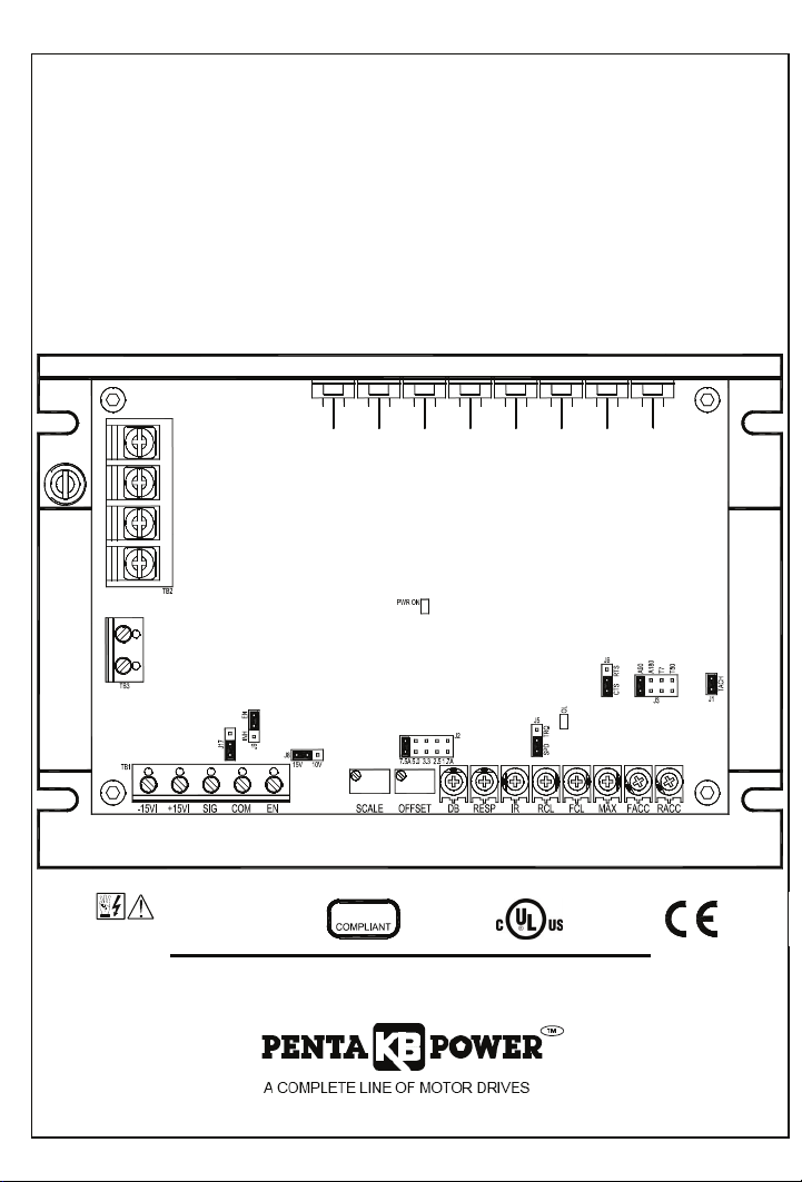
TABLE 1 – STANDARD FEATURES
Feature Description
Terminal Blocks
(See Section 6, on page 13.)
Facilitates wiring of AC line, motor armature and field,
TB1 (-15V, +15V, SIG, COM, EN), TB2 (L1, L2, M2, M1), TB3
(F+, F-).
Connectors
(See Section 7, on page 19.)
J1, Tach-Generator Input – Connection point for an external
Tach-Generator.
Selectable Jumpers
(See Section 7, on page 19.)
J2 - Motor Armature Current
J3 - Motor Armature Voltage
J5 -SPD / TRQ – (Speed / Torque)
J6 -CTS/RTS – (Coast to Stop / Regenerate to Stop)
J8 -Signal Input Source (15V or 10V)
J9 - Enable (EN) / Inhibit (INH)
J17- Analog Signal Input (Voltage/Current)
Trimpots
(See Section 10, on page 25.)
Provide adjustment for Forward Acceleration (FACC), Reverse
Acceleration (RACC), Maximum (MAX), Forward Current Limit
(FCL), Reverse Current Limit (RCL), IR Compensation (IR),
Response (RESP), Deadband (DB), Offset (OFFSET), and
Scale (SCALE).
Diagnostic LEDs
(See Section 11, on page 30.)
For Power On (ON), and Current Limit (OL) indications.
(Current Overload gives indication that the control will trip).
TABLE 2 – SELECTABLE JUMPERS (See Section 7, on page 19)
Feature Description
J2-Motor Current, Refer to Section 7.1, on page
19. For selection of the motor current being used.
J3 – Motor Armature Voltage, Refer to Section
7.2, on page 20.
For selection of the motor voltage being
used.
J5-SPD / TRQ, Speed or Torque, Refer to
Section 7.3, on page 20.
Jumper position is selectable for either Speed
(SPD) or Torque (TRQ) modes.
J6-CTS/RTS. Refer to Section 7.4, on page 21.
For selection of Coast to Stop (CTS) and
Regenerate to Stop (RTS). Works in
conjunction with the Enable circuit.
J8-Signal Input (15V or 10V). Refer to Section
7.5, on page 22.
Used for selection of potentiometer (15V) or
use if the control is to be used from a
0 – ±10/±15VDC.
J17-Signal Input. Refer to Section 7.6, on page
22.
Input signal connection for the use with the
Main Speed Potentiometer. Used for
accepting a 0 – ±10V or 0 – ±25V signal or
4 – 20 ma.
J9-EN (Enable) / INH (Inhibit). Refer to Section
7.7, on page 22.
For selection of electronically starting and
stopping the motor. Used in conjunction with
J6, CTS/RTS.

8
TABLE 3 – TRIMPOT ADJUSTMENTS (See Section 10, on pages 25)
Trimpot Description
Forward Acceleration (FACC). Refer to Section
10.1, page 25.
Sets the amount of time for the motor to
accelerate from zero speed to full speed in the
forward direction and the time it takes to
decelerate in the reverse direction (FACC =
Reverse Deceleration). Factory adjusted to 1
second. (Maximum of 15 seconds).
Reverse Acceleration (RACC). Refer to Section
10.1, on page 25.
Sets the amount of time for the motor to
accelerate from zero speed to full speed in the
reverse direction and the time it takes to
decelerate in the forward direction (RACC =
Forward Deceleration). Factory adjusted to 1
second. (Maximum of 15 seconds).
Maximum Speed (MAX SPD). Refer to Section
10.2, on page 26.
The MAX trimpot is used to set the maximum
output voltage of the control which, in turn, sets
the maximum speed of the motor. In the
Torque Control Mode. The MAX trimpot setting
determines the unloaded motor speed.
Forward Current Limit (FCL). Refer to Section
10.3, on page 26. *
Sets the maximum amount of DC current that
the motor can draw. This determines the
amount of maximum motor torque in both the
Speed Control Mode and Torque Mode.
Reverse Current Limit (RCL) Refer to Section
10.3, on page 26. *
Sets the maximum amount of DC current that
the motor can draw. This determines the
amount of maximum motor torque in both the
Speed Control Mode and Torque Mode.
IR Comp (IR COMP). Refer to Section 10.4,
page 27.
The IR Comp is used to stabilize motor speed
under varying loads.
Response (RESP). Refer to Section 10.5, on
page 28.
This trimpot determines the dynamic response
of the control.
Deadband (DB). Refer to Section 10.6, on page
28.
The DB trimpot sets the amount of main speed
potentiometer rotation required to initiate
control voltage output. It is factory set to
approximately 0%. The DB trimpot also
determines the amount of delay that will occur
before regeneration starts.
Offset (OFFSET). Refer to Section 10.7, on
page 29.
This trimpot determines the amount of bias in
the forward or reverse direction. The trimpot is
factory set to provide approximately zero
offset, which means neither the forward nor
the reverse speed is favored.
Scale (SCALE). Refer to Section 10.8, on page
29.
This trimpot works in conjunction with the
MAX potentiometer for fine tuning of the
(voltage or current) of the incoming analog
signal.
*FCL and RCL also determine the maximum amount of regenerative breaking torque
depending on which direction is braking.

9
TABLE 4 BELECTRICAL RATINGS
Input Voltage
(VAC)
Maximum AC
Line Current
(Amps RMS)
Output
Voltage
(Volts DC)
Maximum
DC Output
Current (ADC)
Maximum
Horsepower
HP, (KW)
115 12 0 – ±90 7.5 ¾, (0.5)
208/230 12 0 – ±180 7.5 1.5, (1)
TABLE 5 BGENERAL PERFORMANCE SPECIFICATIONS
Parameter
Specification
Factory Setting
AC Line Input Voltage (VAC, ±10%, 50/60 Hz) 115 or 208/230 208/230
Armature Voltage Range at 115 VAC Line (VDC) 0 – ±90 —
Armature Voltage Range at 230 VAC Line (VDC) 0 – ±90, 0 – ±180 0 – ±180
Field Voltage at 115 VAC Line (VDC) 100 / 50 —
Field Voltage at 230 VAC Line (VDC) 200 / 100 —
Max Load Capacity (% for 2 Minutes) 150 —
Ambient Temperature Range (ºC / °F) 0 – 40 / 32 – 104 —
Speed Range (Ratio) 50:1 —
Arm Feedback Load Regulation (% Base Speed) ±1 —
Tach Feedback Load Regulation (% Set Speed) ±1 —
AC Line Regulation (% Base Speed) ±0.5 —
Current Ranges (Amps DC) 1.7, 2.5, 5.0, 7.5 7.5
FWD and REV Accel Range (Seconds) 0.1 – 15 1
Deadband Range (% Base Speed) 0 – ±5 0
Max Speed Trimpot Range (% Base Speed) 55 – 110 100
IR Comp Range at 115 VAC Line (VDC) 0 – 20 5
IR Comp Range at 230 VAC Line (VDC) 0 – 40 10
FCL and RCL Range (% Range Setting) 0 – 175 150
Voltage Following Input Range (VDC) ±5 – ±25 0 – ±10, 0 – ±15
Voltage Following Linearity (% Base Speed) ±0.5 —

10
FIGURE 1 BCONTROL LAYOUT
F-F+
M1M2L1 L2

11
FIGURE 2 BMECHANICAL SPECIFICATIONS (Inches / [mm])
M1L1 L2 M2 F+ F-
6.50
[165] [178]
7.00
3.50
[5.08]
0.20
0.625
[15.9]
[88.9]
[6.35]
0.25
[120]
4.75
MAXIMUM HEIGHTS
Without Accessory Boards
1.70
[43.2]
With Accessory Boards
3.10
[78.7]

12
4 IMPORTANT APPLICATION INFORMATION
WARNING! DO NOT USE THIS DRIVE IN AN EXPLOSIVE ENVIRONMENT.
AN EXPLOSION CAN CAUSE SERIOUS OR FATAL INJURY. THIS DRIVE IS NOT
EXPLOSION PROOF.
WARNING! BE SURE TO FOLLOW ALL INSTRUCTIONS CAREFULLY.
FIRE OR ELECTROCUTION CAN RESULT DUE TO IMPROPER USE OF THIS
PRODUCT. READ SAFETY WARNING ON PAGE 5.
4.1 Motor Type – The KBRG-212D is full-wave regenerative control, capable of
operating a DC motor (Permanent Magnet (PM), or Shunt), in a Bi-Directional mode.
Be sure the drive is used within its stated specifications.
4.2 Torque Requirements – When replacing an AC induction motor with a DC motor
and speed control, consideration must be given to the maximum torque
requirements. The full load torque rating of the DC motor must be equal to, or
greater than, that of the AC motor.
4.3 Acceleration Start – The KBRG-212D contains an adjustable acceleration
start feature that allows the motor to smoothly accelerate from 0-full speed over a
time period of 0.5 to 15 seconds.
4.4 Limitation in Use – The KBRG-212D controls are designed for use on
machine applications.
CAUTION! - Do not use in explosive atmosphere. Be sure the KBRG-212D is
used within its maximum ratings. Follow all installation instructions carefully (Refer to
Sections 4 and 5).
5 MOUNTING INSTRUCTIONS
Mount the KBRG-212D on a flat surface free of moisture, metal chips, or corrosive
atmosphere. Refer to Figure 2, on page 11.
A 5kΩohm remote potentiometer is provided. Install the potentiometer using hardware
provided. Be sure to install insulating disk between potentiometer and inside of front panel.
Enclosure – When mounting the KBRG-212D in an enclosure, it must be large enough to
allow for proper heat dissipation. A 12” x 12” x 24” enclosure is suitable for the KBRG-212D at
full rating. Smaller enclosures may be used if full rating is not required.

13
6 ELECTRICAL CONNECTIONS
WARNING! READ SAFETY WARNING, ON PAGE 5, BEFORE USING THIS
CONTROL.
CAUTION! To avoid erratic operation, do not bundle AC line and motor connections
with potentiometer connections, voltage following connections, Start/Stop switch
connections, inhibit connections, or any other signal connections. Use shielded
cables on all signal connections over 12” (30 cm) long. Shield should be earth
grounded on the control side only.
Connect control in accordance with National Electric Code requirements and other local
codes that apply. The KBRG-212D does not contain AC line or armature fusing. It is
recommended that a 20 Amp fuse or circuit breaker be installed on each AC line
conductor not at ground potential. Connect control, in accordance with illustrations in this
section. A separate AC line switch or contactor must be connected as a disconnect switch
so that contacts open each ungrounded conductor. In addition, Table 6, details the
connection, wiring and torque information.
6.1 AC Line Connection – Connect the AC line to L1 and L2 terminals of TB1 as
shown in Figure 3, on page 14.
Note: There are no AC Line or Armature fuses supplied with this control. See Section
6.3, on page 14.
6.2 Motor Armature – Connect motor armature to terminal Ml and M2. (Be sure
jumper J3 is set to match motor voltage. See Figure 3, on page 14 and Section
7.2, on page 20.
TABLE 6 – TERMINAL BLOCK WIRING INFORMATION
Supply Wire Gauge
(AWG – Copper)
Terminal Block
Designation Connection
Designation Minimum Maximum
Maximum
Tightening
Torque
(lbs- in)
TB1 Power / Control
Connections 22 14 3.5
TB2 L1, L2, M1, M2 18 12 3.5
TB3 F+, F- 22 14 3.5

14
FIGURE 3 – AC LINE AND ARMATURE CONNECTION
F+ F-
TB3
(EARTH)
GND
-
+
M
AC LINE
INPUT
L1 L2 M2 M1
ARMATURE
FUSE
FUSE
FUSE
TB2
See Table 6, for Torque Requirements.
6.3 Fusing
AC Line Fuse – The KBRG-212D does not contain an AC line fuse or Armature
fuse. It is recommended that a 20 Amp fuse or circuit breaker be installed on
each AC line conductor not at ground potential. In addition, refer to Table 7, for
recommended Armature Fusing.
CAUTION: Most electrical codes require that each ungrounded conductor contain
fusing. Separate branch circuit fusing may be required. Check local electrical codes.
6.4 Motor Armature – Connect motor armature to terminals M1 and M2. Be sure that
jumper J2 matches the motor being used. (See Figure 3).
TABLE 7 – ARMATURE FUSE CHART
Motor Horsepower
90 VDC 180 VDC
Approx. DC Motor
Current Amps
Fuse Rating
(AC Amps)
1/8 ¼ 1.3 2
1/6 1/3 1.7 2 ½
¼ ½ 2.5 4
1/3 ¾ 3.3 5
½ 1 5.0 8
¾ 1 ½7.5 12
1 2 10.0 20
6.5 Field (For Shunt Wound Motors Only) – Connect motor armature leads as above.
Connect full voltage shunt field leads (90 volt motors with 100 volt fields and 180 volt
with 200 volt fields) to F+ and F-. Connect half voltage field leads (90 volt motors
with 50 volt fields and 180 volt motors with 100 volt fields) to F+ and L1. See Table
8, Figures 4 and 5, on page 15, for field connection diagrams.
CAUTION! Shunt-Wound motors may be damaged if field remains connected without
motor rotating for an extended period of time.
Note: Do not connect motor armature leads to F+ and F- terminals. Do not use F+ and F-
terminals for PM motors.

15
TABLE 8 – FIELD CONNECTIONS (Shunt Wound Motors Only)
AC LINE
VOLTAGE
FIELD VOLTAGE
(VDC)
FIELD VOLTAGE
(VDC) FIELD CONNECTION
115 90 100 F+, F-
115 90 50 F+, L1
230 180 200 F+, F-
230 180 100 F+, L1
230 *90 100 F+, L1
*Step down operation. See Section 7.2, on page 20.
6.6 Full Voltage Field
Connection (Shunt
Wound Motors Only) –
Connect the motor field
leads to F+ and F-
terminals of TB3 as
shown in Figure 4, and
Table 7, on page 14.
Note: Do not connect
motor armature
leads to F+ and
F- terminals.
CAUTION! Do not use F+
and F- terminals of TB3 for
any purpose other than to
power the field of a shunt
wound motor.
6.7 Half Voltage Field
Connection (Shunt
Wound Motors Only) –
Connect the motor field
leads to F+, TB3 and L1
terminals of TB2, as
shown in Figure 5, and
Table 7, on page 14.
CAUTION! TB3 terminals are
not isolated from AC line. Do
not ground (earth).
Note: Do not connect
motor armature
leads to F+ and
F- terminals.
FIGURE 4 BFULL VOLTAGE FIELD CONNECTION
FIELD
F+ F-
-
+
M
AC LINE
INPUT
L1 L2 M2 M1
ARMATURE
FUSE
FUSE
GND
(EARTH)
FUSE
TB2
TB3
See Table 6, for Torque Requirements.
FIGURE 5 BHALF VOLTAGE FIELD CONNECTION
ARMATURE
L1 L2 M2 M1
AC LINE
INPUT
M
+
-
F+ F-
FIELD
FUSE
FUSE
GND
(EARTH)
TB2 TB3
See Table 6, for Torque Requirements.

16
6.8 Main Speed Potentiometer Connection – The main speed potentiometer can be
connected in several ways. (A 5kΩohm potentiometer is supplied with control. A 10K
potentiometer can also be used.) See Figures 6A – 6D.
6.8.1 Unidirectional operation (FORWARD) – Connect potentiometer to terminals
“+15,” “SIG,” “COM” for forward direction as per Figure 6A.
6.8.2 Unidirectional operation (REVERSE) – Connect potentiometer to terminals
“-15,” “SIG,” “COM” for reverse direction. As per Figure 6B.
6.8.3 Bidirectional operation using reversing contacts – Connect potentiometer
to terminals “-15,” “+15”, “SIG,” “COM” as per Figure 6C.
6.8.4 Bidirectional operation with potentiometer – Connect potentiometer to
terminals “-15,” “+15” “SIG” as per Figure 6D.
FIGURE 6A – UNIDIRECTIONAL
OPERATION (Forward)
FIGURE 6B – UNIDIRECTIONAL
OPERATION (Reverse)
Main Speed Potentiometer
TB1
-15 +15 SIG COM
*
-15 +15 SIG COM
TB1
Main Speed Potentiometer
*
FIGURE 6C – BIDIRECTIONAL
OPERATION (Reversing Contact)
FIGURE 6D – BIDIRECTIONAL with
POTENTIOMETER
Main Speed Potentiometer
TB1
-15 +15 SIG COM
*FWD / REV
SWITCH
Main Speed Potentiometer
TB1
-15 +15 SIG
*
Center Pot Position = 0 Speed
CW = Full Forward
CCW = Full Reverse
See Table 6, for Torque Requirements.
Notes: 1. * Indicates increase in motor speed. 2. A connection must be made between
EN and COM terminals (TB1) to operate when J9 is in the EN position.

17
6.9 Signal Following – In this mode, a signal source is used to vary motor speed.
6.9.1 Voltage Following – Uses a voltage source to vary motor speed. Set J17
(See Section 7.7 on page 22 for jumper information) to “VOLT” position and
connect the voltage source to TB1 terminals SIG (+) and COM (-) (See
Figures 7A below and 7C, on page 18), Voltage Following Connection. Be
sure the positive (+) signal is connected to “SIG” terminal and the negative
(-) is connected to the “COM” terminal. When a 0V DC signal is applied, the
motor will operate at the minimum set speed (set by the MIN Trimpot). When
a 10V DC signal is applied, the motor will operate at the maximum set speed
(set by the MAX Trimpot).
6.9.2 Current Following – Uses a current source to vary motor speed. Set J17
(See Section 7.7 on page 22 for jumper information) to “CUR” position and
connect the current source to TB1 terminals SIG (+) and COM (-). See
Figures 7B below, and 7D, on page 18.
In addition, the control is used to isolate, amplify, and condition DC voltage
signals from any external source (power supplies, motors, tachometer
generators, transducers, and potentiometers). Also provides isolation for
motor direction, switching and an isolated power supply for transducer or
potentiometer operation. See Section 7.7, on page 22.
Notes:
1. Jumper J8 must be in the “10V” position.
2. A positive signal with respect to the COM terminal will produce a positive
output to motor. A negative signal with respect to the COM terminal will
produce a negative output. A 0 to ±10VDC is required to operate control
from 0 to ± full output. Jumper J8 must be set to the 10V position.
FIGURE 7A – VOLTAGE FOLLOWING
(DEFAULT)
FIGURE 7B – CURRENT FOLLOWING
±10 VDC
SIG (+) COM (-)
~
TB1
J17
VOLT CUR
SIG (+) COM (-)
4 - 20mA
TB1
VOLT CUR
J17
See Table 6, for Torque Requirements.

18
FIGURE 7C - J17
VOLTAGE SCALE
FIGURE 7D - J8
CURRENT SCALE
10
0 15
J17
90V /
180 V
4
90V /
20mA
J17
6.10 Enable / Inhibit – The control features an Enable / Inhibit function. The control can
be electronically stopped and started with the Enable / Inhibit circuit.
The Enable circuit functions opposite to that of the inhibit circuit. Inhibit: open to start,
close to stop. Enable: open to stop, close to start.
6.10.1 Enable Mode, EN (212D) – In the Enable mode (Default) connect COM
terminal to the EN terminal via a switch. See Figure 8A.
6.10.1 Inhibit Mode, INH (213D) – When COM terminal and EN terminal are open,
control is in “INHIBIT” state. See Figure 8B.
IMPORTANT NOTE: In Enable mode a switch must be installed between the COM
and the EN terminals or control will not operate. See SAFETY WARNING, on page 5.
FIGURE 8A– ENABLE MODE
(CLOSE TO RUN)
FIGURE 8B – INHIBIT MODE
(CLOSE TO STOP)
COM EN
TB1
JUMPER J9
INH EN
SWITCH
JUMPER J9
JUMPER
COM EN
INH EN
TB1

19
6.11 Tach-Generator Feedback, J1 – The KBRG-212D is
factory set for armature feedback which provides good
load regulation for most applications. For superior
load regulation analog tach-generator feedback can
be used.
Connect the tach-generator to J1, so that the polarity
of the tach-generator is the same with respect to the
input signal polarity.
Note: If tach-generator is wired for reverse polarity,
the motor will run at full speed. See Figure 9.
7 SETTING SELECTABLE JUMPERS
The KBRG-212D has customer selectable jumpers which must be set before the control
can be used. See Figure 1, on page 10 for jumper locations.
7.1 J2 – Armature Current – Select the J2 position (1.7, 2.5, 3.3, 5, 7.5) closest to the
rated motor current. See Figure 10 and Table 9.
Note: The maximum output current is set to 150% of the J2 position, which may be reset
using the FCL and RCL Trimpots. See Section 10.3, on page 26.
FIGURE 9 –
J1 -TACH-GENERATOR
FEEDBACK
+ -
G
J1
+ -
FIGURE 10 - J2 – ARMATURE
CURRENT JUMPER
(SHOWN IN FACTORY SETTING)
2.5A
7.5A 1.7A3.3A5.0A
J2
TABLE 9 –
MOTOR HORSEPOWER
J2 Position
Motor
Current
(DC Amps)
90 VDC 180 VDC
7.5A 3/4
1 ½
5.0A 1/2 1
3.3A 1/3 3/4
2.5A 1/4 1/2
1.7A 1/6 1/3

20
7.2 J3 – Armature Voltage
Output and Tach-Generator
Feedback – Select the
desired armature voltage by
placing J3 in the proper
position, “A90" or “A180.”
See Figure 11A.
Note: For 115 volt AC
line input, J3 must be
set to “A90.” For 230
input, the armature
voltage is normally
set for “A180.” However, it is also possible to set the armature voltage to “A90" for
stepdown operation.
7.2.1 Tach-Generator Feedback (for use with 1800 RPM motors.) – Jumper J3 is also
used if tach-generator feedback is to be used. If a 7 volt per 1000 RPM tach-
generator is used, set jumper J3 in the “T7" position. For a 50 volt per 1000 RPM
tach-generator, set the jumper in the “T50" position. See Figure 11B.
Note: When using tach-generator feedback, the
IR Comp Trimpot (See Section 10.4, on
page 27) should be turned to a
minimum setting (full CCW). See
Figure 9, and Section 6.11, on page 19.
7.3 J5 - Speed (SPD) or Torque (TRQ).
Note: Factory setting of J5 is Speed
mode (Default).
In the speed control mode (J5 set to SPD), the
KBRG-212D will provide variable speed
control. The motor speed will be in direct
proportion to the input signal. Both forward and
reverse torque is used to stabilize motor
speed.
See Figures 12, 13 and 14.
FIGURE 11A – J3
ARMATURE VOLTAGE
(90V)
FIGURE 11B – J3
ARMATURE VOLTAGE
(180V)
(Default Position)
FIGURE 12 – J5
SPEED / TORQUE (SPD or TRQ)
Default Position
(
Shown in the Tor
q
ue Mode
)
FIGURE 13 – SPEED MODE vs. MOTOR LOAD
CL SETPOINT
APPLIED TORQUE
MOTOR SPEED (%)
100
90
80
70
60
50
40
30
20
10
0
0 10 20 30 40 50 60 70 80 90 100 110 120 130 140 150
HIGHER SET SPEED
LOWER SET SPEED
Other manuals for Penta Power KBRG-212D
1
Table of contents
Other KB Electronics DC Drive manuals

KB Electronics
KB Electronics Penta Power KBRG-255 User manual

KB Electronics
KB Electronics PENTA KB POWER KBRG-225D User manual

KB Electronics
KB Electronics KBWS-12 User manual

KB Electronics
KB Electronics Penta Power KBRG-212D User manual

KB Electronics
KB Electronics KBAC-24D User manual

KB Electronics
KB Electronics Penta Power KBVF Series User manual

KB Electronics
KB Electronics KBPC-240D Configuration guide

KB Electronics
KB Electronics KBBC Series User manual