KBR multimess F144-PQ User manual

28592_EDEKZA0044-0224-1_EN
System Ienglish
Quick guide
Installation guidelines
In our download center you will nd the
appropriate instructions for KBR devices.
https://www.kbr.de/de/dienstleistungen/
download-center
Power Quality Analyser
multimess F144-PQ

28592_EDEKZA0044-0224-1_EN
2
1. Notes..................................................................................................................................................4
1.1 General information .....................................................................................................................4
1.2 Revisions...........................................................................................................................................4
1.3 Waranty............................................................................................................................................. 4
2. Safety .................................................................................................................................................5
2.1 Safety Instructions......................................................................................................................... 5
2.2 Structure of the warnings...........................................................................................................6
2.3 Graduation of warnings .............................................................................................................. 6
2.4 Intended use ...................................................................................................................................7
2.5 Other applicable ............................................................................................................................ 7
2.6 Target group.................................................................................................................................... 7
2.7 Cleaning............................................................................................................................................8
2.8 Meaning of the symbols used on the device ......................................................................8
3. Commissioning ..............................................................................................................................9
KBR Kompensationsanlagenbau GmbH does not accept any liability for any loss or
damage resulting from printing errors in or changes to this manual.
In addition, KBR Kompensationsanlagenbau GmbH does not accept any liability for
any loss or damage caused by defective devices or devices manipulated by the user.
Copyright 2024 by KBR Kompensationsanlagenbau GmbH
Subject to change.
Table of contents

28592_EDEKZA0044-0224-1_EN
3
Table of contents
3.1 multimess F144-PQ Summary description...........................................................................9
3.2 Lieferumfang...................................................................................................................................9
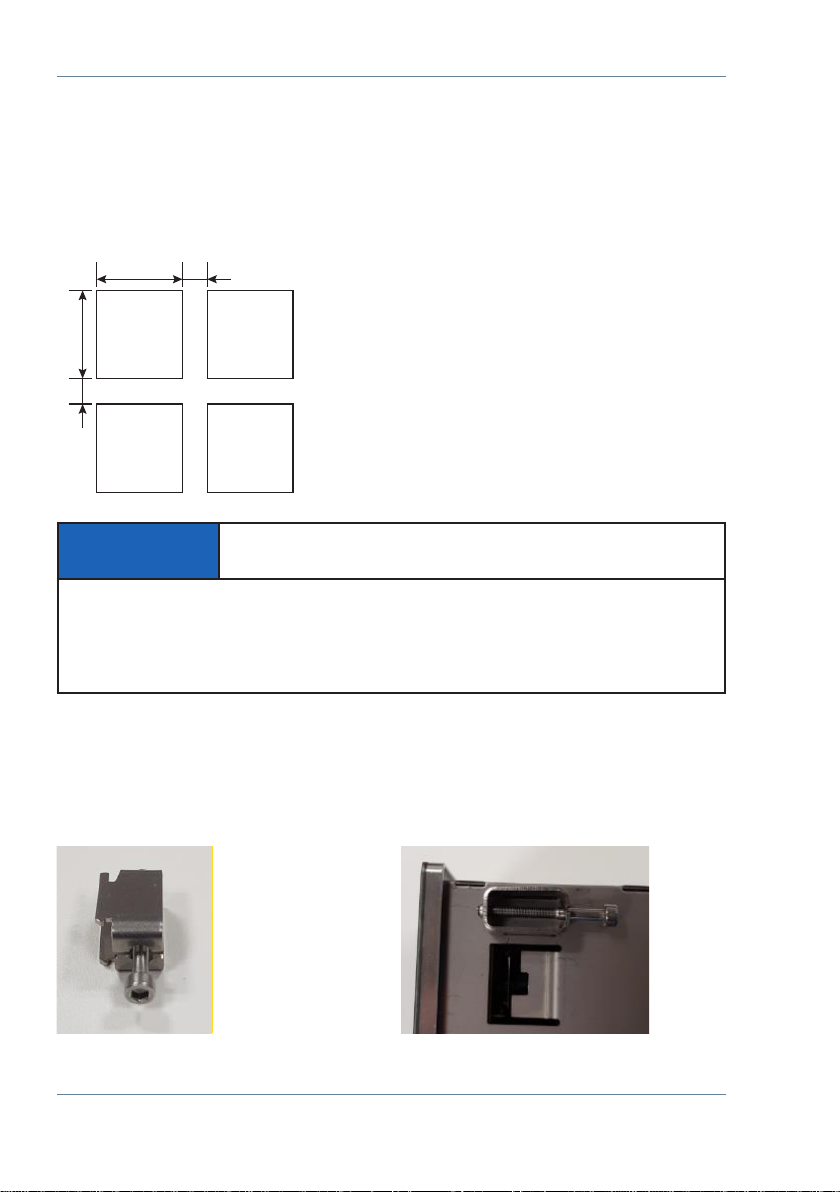
3.3 Fitting...............................................................................................................................................10
3.4 Protection earth...........................................................................................................................11
3.5 Supply voltage..............................................................................................................................12
3.6 Mains connection for multimess F144-PQ .........................................................................14
3.6.1 3-phase / 4-wire connection....................................................................................................15
3.6.2 3-Phase / 4-wire connection without neutral current....................................................17
3.6.3 4-wire / 1-phase ...........................................................................................................................18
3.6.4.1 Connection tranformer for feature........................................................................................19
3.6.4.2 Connection to voltage sensors...............................................................................................20
3.6.4.3 Aron / V circuit ..............................................................................................................................21
4. Operation of the multimess F144-PQ...................................................................................22
4.1 Getting started .............................................................................................................................22
4.2 Initial Setup - Operation of the Assistant............................................................................22
4.3 First commissioning - wizard - procedure ..........................................................................23
4.3.1 Wizard setting Language..........................................................................................................23
4.3.2 Wizard setting Power Quality standard...............................................................................23
4.3.3 Wizard setting Net type.............................................................................................................24
4.3.4 Wizard setting Net frequency .................................................................................................24
4.3.5 Wizard setting Voltage Transformer......................................................................................25
4.3.6 Wizard setting Voltage Grid.....................................................................................................25
4.3.7 Wizard setting Current Transformer......................................................................................26
4.3.8 Wizard setting Rated Current..................................................................................................26
4.3.9 Wizard setting Date, Time and Timezone ...........................................................................27
4.3.10 Wizard setting Interface............................................................................................................28
4.3.11 Wizard setting Security Mode.................................................................................................29
4.3.13 Wizard End of commissioning ................................................................................................30
5. Technical Data...............................................................................................................................31
5.1 Dimensions / Weight..................................................................................................................31
5.2 Electrical safety – environmental parameter.....................................................................31
5.3 Power supply.................................................................................................................................32
5.4 Voltage Inputs...............................................................................................................................32
5.5 Current Inputs...............................................................................................................................33
5.6 Binary inputs .................................................................................................................................33
5.7 Binary outputs ..............................................................................................................................34
5.8 Temperature Input......................................................................................................................34
5.9 Electrical safety.............................................................................................................................35
5.10 Connection / terminals..............................................................................................................36

28592_EDEKZA0044-0224-1_EN
4
1. Notes
1.1 General information
These installation instructions contain all-important information for mounting and com-
missioning. Read the manual carefully and completely, it contains important information
about the product. Observe the notes and follow the safety and warning instructions in
particular. Keep the manual carefully and ensure that it is always available and can be
viewed by the user of the product.
The company KBR Kompensationsanlagenbau GmbH does not accept any liability for
damage or loss of any kind resulting from failure to observe the product information or
resulting from printing errors or changes in this installation guidelines. The company KBR
Kompensationsanlagenbau GmbH does not accept any liability for damage or loss of any
kind resulting from faulty devices or from devices that have been modied by the user.
1.2 Revisions
Please note that these installation instructions may not always represent the most up-
to-date information on the device. If, for example, you have changed the rmware of the
device in the direction of a later rmware version, the present installation instructions
may no longer be suitable in every point.
In this case, either contact us directly or use the latest version of the installation instruc-
tions available on our website (www.kbr.de) and the other documents available for the
device.
Copyright 2024 KBR Kompensationsanlagenbau GmbH
Subject to change without notice
1.3 Waranty
We guarantee that every product KBR Kompensationsanlagenbau GmbH is free
from material and manufacturing defects under normal use.
The detailed conditions for the warranty can be found in our general terms and
onditions of business under: https://www.kbr.de
Introduction

28592_EDEKZA0044-0224-1_EN
5
2. Safety
2.1 Safety Instructions
IT IS IMPORTANT FOR PERSONAL SAFETY TO FOLLOW THESE INSTRUCTIONS.
THESE INSTRUCTIONS MUST BE KEPT IN A SAFE PLACE!
Observe operating instructions.
Always keep the operating instructions with the appliance.
Ensure that the machine is only operated in perfect condition.
Never open the device.
Ensure that only qualied personnel operate the device.
Only connect the device according to instructions.
Ensure that the device is only operated in its original condition.
Only operate the device with recommended accessories.
Ensure that the device is not operated above its rated data
(see technical data in chapter 5)
Ensure that the original accessories are not operated above the rated data.
Do not operate the device in environments where explosive gases,
dust or vapours are present.
The installation instructions do not represent a complete list of all safety instructions
necessary for the operation of the device. Special operating conditions may require
further instructions. The installation instructions contain information that you must
observe for your personal safety and to prevent damage to property.
Introduction

28592_EDEKZA0044-0224-1_EN
6
2.2 Structure of the warnings
Warnings are structured as follows:
SIGNAL WORD
Nature and source of the danger!
Consequences if not observed.
Steps to avoid the danger.
2.3 Graduation of warnings
Warnings dier according to the type of danger as follows:
DANGER!
Warns of an imminent danger which, if not avoided,
will result in death or serious injury.
WARNING!
Warns of a potentially dangerous situation that can result
in death or serious injuries when not avoided.
CAUTION!
Warns of a potentially dangerous situation that can result
in fairly serious or minor injuries when not avoided.
NOTICE! Warns of a potentially dangerous situation that if not
avoided could result in material or environmental damage.
Refers to processes where there is no risk of injury or
damage to property, but which must be observed for reliable
operation of the device!
Introduction

28592_EDEKZA0044-0224-1_EN
7
2.4 Intended use
The product is designed exclusively for the measurement and evaluation of voltage and
current signals in the energy network. If the measuring device is used in a way which
is not specied by the manufacturer, the protection supported by the device can be
severely limited. The device is intended for use for measurement in the low voltage range
in CAT IV (300 V) up to a maximum of 690 V (conductor/conductor). Other voltage levels
such as medium- or high-voltages must be connected to the instrument via voltage
transformers. All technical connection values and rated data must be observed!
The multimess F144-PQ is suitable for the following installation location and should,
should only be operated in this environment.
Mounting in a control cabinet and compact distribution board
2.5 Other applicable
For the safe and correct use of the device, please also observe the other documents
such as the complete operating instructions and the additional documents supplied,
as well as the relevant standards and laws.
2.6 Target group
These installation instructions are intended for trained specialist sta as well as trained
and tested operating personnel. The contents of these installation instructions must
be made available to the persons entrusted with the installation and operation of the
system. In order to avoid damage to property and personal injury, the qualied personnel
must be trained electro technically and have the following knowledge.
Knowledge of national accident prevention regulations
Knowledge of safety engineering standards
Knowledge of installation, commissioning and operation
Introduction

28592_EDEKZA0044-0224-1_EN
8
Introduction
2.7 Cleaning
Use a soft, slightly moistened and lint-free towel. Make sure that no moisture penetrates
the housing. Do not use window cleaners, household cleaners, sprays, solvents, cleaners
containing alcohol, ammonia solutions or scouring agents for cleaning. Please use only
water for cleaning.
2.8 Meaning of the symbols used on the device
Nature and source of the danger!
Read the safety instructions inside the manual!
Functional earth of the measuring device
USB-Interface
TCP-IP Interface
CE marking guarantees compliance with the European directives
and regulations regarding Electromagnetic Compatibility (EMC).
Alternating voltage (AC)
Direct voltage (DC)

28592_EDEKZA0044-0224-1_EN
9
Commissioning
3. Commissioning
3.1 multimess F144-PQ Summary description
The Power Quality Analyser and Fault Recorder multimess F144-PQ for low, medium and
high voltage networks is the central component of a system with which all measurement
tasks in electrical networks can be solved.
The multimess F144-PQ can be used as a Power Quality Interface according to power
quality standards such as IEC61000-2-2 / EN50160 or to check the technical con-nection
guidelines such as DIN VDE AR 4110 and DIN VDE 4120 and many more. Due to the availa-
ble SCADA interfaces such as Modbus RTU/TCP as well as IEC 61850, the device can also
be used as a highly accurate measurement transducer for all physically dened measured
variables in 3-phase systems parallel to the continuous recording of measured values
over a very long period.
In addition to the possibility of standard evaluations, the multimess F144-PQ also has a
high-speed disturbance recorder with a recording rate of 40.96 kHz/10.24 kHz and a 10ms
TRMS eective value recorder. This allows a detailed evaluation of grid disturbances.
3.2 Lieferumfang
multimess F144-PQ
Installations guidlines
Ethernet cable
Calibration certicate

28592_EDEKZA0044-0224-1_EN
10
Commissioning
3.3 Fitting
The multimess F144-PQ is used as a panel-mounted device and fulls IP54 in the installed
condition. Mounting must be carried out with the following cut-outs and mini-mum dis-
tances (see following gure). The maximum thickness of the panel for PQI-DE installation
is 8mm.
For mounting the multimess F144-PQ, four mounting brackets are included in the scope
of delivery. These must be snapped into the housing of the multimess F144-PQ at all four
corners (see picture below). The clamps must then be screwed against the panel with a
maximum torque of ve Nm using an Allen key (2.5 mm) on the back of the PQI-DE to
ensure that the PQI-DE is securely mounted in the panel cut-out.!
138+1 min. 40
min. 40 138+1
Panel cut-out
Mounting bracket
for multimess F144-PQ
Mounting bracket engaged
on multimess F144-PQ
NOTICE! Material damage due to non-observance
of the installation instructions!
Non-observance of the installation instructions or incorrect installation can damage
the device!
Pay attention to the audible snapping of the mounting elements

28592_EDEKZA0044-0224-1_EN
11
Commissioning
3.4 Protection earth
The device has a protective earth, which also serves as reference potential for the voltage
inputs.
The protective earth is marked with and terminal X1 / 13 on the measuring
instrument.
Connect the earth cable to terminal X1 / 13 on the meter and tighten the screw. Use an
eyelet terminal for the connection and make sure it is tight!
DANGER! Danger to life due to electric shock!
Incorrect connection of this measuring instrument can lead to death,
serious injury or re hazard!
The functional earth must always be connected to PE potentia.
The functional earth must not carry a dangerous voltage under any circumstance.

28592_EDEKZA0044-0224-1_EN
12
After connecting and switching on the power supply, the status LED lights up red,
changes to green and the display starts in the commissioning wizard.
DANGER! Danger to life due to electric shock!
Serious personal injury or death may result from:
Touching bare or stripped wires that are energised.
Touching dangerous inputs on the device.
Make sure that the device is connected in a de-energized state.
Ensure that all connecting cables are xed and strain relief is provided.
All cable requirements of the terminal blocks must be observed.
(e.g. stripping length of the cables).
3.5 Supply voltage
The multimess F144-PQ is available in two dierent supply voltage versions.
Please take the correct supply voltage from the type label before connection.
Example of connection to 230 V AC
Commissioning

28592_EDEKZA0044-0224-1_EN
13
Commissioning
NOTICE! Material damage due to non-observance of the
connection conditions or impermissible overvoltage!
Failure to comply with the connection conditions or exceeding the permissible voltage
range may damage or destroy your device.
Before applying the supply voltage to the device, the following points must be
observed:
Voltage and frequency must correspond to the specications on the type label!
Observe the limit values as described in the technical data!
Observe features of the device
In the building installation, the supply voltage must be provided by a listed
miniature circuit breaker and fuse that meets the requirements of IEC 60947-1 and
IEC 60947-3!
The miniature circuit breaker must
- be easily accessible to the user and installed close to the device.
- Label for the respective device.
Do not take the supply voltage at the voltage transformers.
Provide a fuse for the neutral conductor if the neutral connection
of the source is not earthed

28592_EDEKZA0044-0224-1_EN
14
3.6 Mains connection for multimess F144-PQ
The mains connection of the multimess F144-PQ depends on the type of mains in which
the measurement is to be made.
The multimess F144-PQ is designed for direct measurement in low voltage (3 phase / 4
wire connection) for low voltage networks (TN, TT and IT networks) or for residential and
industrial applications. A special form of low voltage measurement is the measurement
4-wire / 1 phase connection with which three independent voltage circuits and current
circuits can be measured with the same ground conditions.
For medium and high voltage the device can be connected via suitable transformers.
A connection with three voltage and current transformers is possible as well as the con-
nection via transformer saving circuits (V-circuit, Aron circuit).
In addition, current measurements with small signal inputs are possible with the corres-
ponding sensor transformers
WARNING!
Personal injury and damage to property due to
nonobservance of the safety regulations
Before making any connections, please read this manual thoroughly and
follow the safety measures described here.
Commissioning

28592_EDEKZA0044-0224-1_EN
15
3.6.1 3-phase / 4-wire connection
Example of a connection for a multimess F144-PQ in a three-phase four-wire system
Voltage connections
The voltage connections must be made as shown in the circuit diagram above
If no N conductor connection is available, connect connections E and N together.
Make sure that the switching mode (4-wire) is set
(settings are described in chapter 4.3).
Current connections
The multimess F144-PQ is designed for measuring circuits.
Depending on the feature, the current transformer ratio is factory-set to
nominal current (e.g. 5A) and must be adapted to the transformers used.
Only alternating currents can be measured, not direct currents.
Commissioning

28592_EDEKZA0044-0224-1_EN
16
Commissioning
DANGER! Danger to life due to electric shock!
Attention dangerous contact voltage!
Flashover and high short-circuit currents possible in CAT III and CAT IV!
Ensure that the PE conductor (earthing) is connected to the multimess F144-PQ.
Before starting work, check that no voltage is present!
Provide protective equipment for CAT II, CAT III or CAT IV.
High-load fuses >10 kA or >50 kA must be used in accordance with the CAT.
Short-circuit current transformers before starting work.
Ensure that all connecting cables are xed and strain-relieved.
All cable requirements of the terminal blocks must be observed
(e.g. stripping length of the cables)

28592_EDEKZA0044-0224-1_EN
17
3.6.2 3-Phase / 4-wire connection without neutral current
multimess F144-PQ without neutral conductor Current transformer in 4-wire connection
Voltage connections
If no N conductor connection is available, connect connections E and N together.
Make sure that the switching mode (4-wire) is set
(settings are described in chapter 4.3).
Current connections
If no neutral conductor current is available in the 3-phase / 4-wire net-work, the S2
current inputs of the multimess F144-PQ must all be short-circuited and the S2
terminals of the current transformers used must be connected to S1 (terminal X6:67).
The multimess F144-PQ is designed for measuring circuits
Commissioning

28592_EDEKZA0044-0224-1_EN
18
3.6.3 4-wire / 1-phase
DANGER! Danger to life due to electric shock!
Attention dangerous contact voltage!
Flashover and high short-circuit currents possible in CAT III and CAT IV!
Ensure that the PE conductor (earthing) is connected to the multimess F144-PQ.
Before starting work, check that no voltage is present!
Provide protective equipment for CAT II, CAT III or CAT IV.
High-load fuses >10 kA or >50 kA must be used in accordance with the CAT.
Short-circuit current transformers before starting work.
Ensure that all connecting cables are xed and strain-relieved.
All cable requirements of the terminal blocks must be observed
(e.g. stripping length of the cables)
multimess F144-PQ in 4-wire connection / 1-phase
In the 4-wire network, 1-phase circuit type, no wire-conductor events and threephase
network events are evaluated. Voltages with the same earth potential can be connected
(e.g. three networks with phase L1) and any currents can be connected.
Commissioning

28592_EDEKZA0044-0224-1_EN
19
3.6.4 3-phase / 3-wire connection
3.6.4.1 Connection tranformer for feature
multimess F144-PQ in 3-wire connection for medium and high-voltage via transformer
Voltage connections
Make sure that the measuring cable N / E is connected to terminal 34 for each
measurement. This is usually the earthing point of the voltage transformer.
Ensure that the switching mode (3-wire) is set (settings are described in chapter 4.3).
Set the voltage transformation ratio
Enter the nominal voltage of the conductor-conductor voltage.
Current connections
Set current transformer ratio.
Connection multimess F144-PQ current IN in 3-wire network
If a current is connected to input IN in the 3-wire network, it is
not physically measured. The current IN is always calculated in
3-wire operation.
transducer settings
The transducer settings are set in the assistant in the chapter
„Parametrization“ (see User Manual).
Commissioning

28592_EDEKZA0044-0224-1_EN
20
3.6.4.2 Connection to voltage sensors
multimess F144-PQ in 3-wire connection for medium and high-voltage via voltage sen-
sors
Voltage connections
Ensure that terminals 37 & 38 (N/E) are short-circuited for each measurement.
Ensure that the shielding of the voltage sensors is grounded on both sides.
Set the voltage transformation ratio.
Ground loops must be avoided! If there is a potential
dierence, only one side of the shielding must be grounded!
Ensure that the switching mode (3-wire) is set (settings are described in chapter 4.3).
Set the voltage transformation ratio.
Enter the nominal voltage of the conductor-conductor voltage.
Current connections
Set current transformer ratio.
Connection multimess F144-PQ current INin 3-wire network
If a current is connected to input INin the 3-wire network,
it is not physically measured. The current INis always calculated
in 3-wire operation.
Commissioning
Table of contents