manuals.online logo
Brands
  1. Home
  2. •
  3. Brands
  4. •
  5. KBSOUND
  6. •
  7. Stereo System
  8. •
  9. KBSOUND Select kit User manual

KBSOUND Select kit User manual

Identify the parts included in the KBSOUND SELECT kit
2 1/2”, 16 ohms loudspeakers
2 1/2”, 16 ohms loudspeakers with IR receiver
electronic unit
wire protection box
®
Mremote control
I
D
E
P
Drill
Foret
Drill two 3 in. diameter holes in the to house loudspeakers and . Note that, to be able
to receive the infrared rays from the remote control, should be located in a visible spot that is not hindered by any obstacles.
D I
D
(76mm) surface where the loudspeakers and receiver are to be installed
The minimum distance
recommended between the set formed by the electronic device joined together with the protection box and any source of water or humidity is 6 3/4 ft. (2 m). It
is not recommended that the electronic device be enclosed in a location without proper ventilation.
Realizar en la superficie donde se vayan a instalar los altavoces y el receptor dos taladros de diámetro 3 in. (76mm) para la ubicación de los altavoces e .
Tener en cuenta que debe estar en un lugar visible y libre de obstáculos para recibir los rayos infrarrojos del mando a distancia. La distancia mínima
aconsejada entre el módulo de electrónica junto con la caja protectora y cualquier foco de agua o humedad debe ser de 6 3/4 ft. (2 m). Es conveniente que
el módulo de electrónica no quede encerrado en una ubicación carente de ventilación.
Faire à la surface où on veut installer et le recepteur deux trous avec le foret de 3 in. (76mm) de diamètre pour placer à cet endroit
et , Il faut tenir compte du fait qu´il doit être à un endroit visible et sans obstacle pour recevoir les rayons infrarouges de la télécommande . La
distance minimale conseillé e entre le module d'électronique accompagné du boîtier de protection et n'importe quel point d'eau ou d'humidité doit être de 6
3/4 ft. (2 m). Il est préférable que le module ne soit pas enfermé dans un endroit sans aération.
E P
D I
D
E P
D I
E
Taladrar
les haut-parleurs les haut-
parleurs
P
M
GER
Identifier les éléments qui composent le kit KBSOUND SELECT
télécommande
hauts-parleurs de 2 1/2”, 16 ohms
hauts-parleurs de 2 1/2”, 16 ohms plus capsule receptrice
module d’électronique
®
M
I
D
E
Pboîtier de protection
RÉGLETTE DE CONNEXION
I
D
C
N
L
Haut-parleur de gauche (borne rouge/+)
Haut-parleur de droite (borne rouge/+)
Masse audio ( borne noires/-)
Connecteur capsule receptrice de la télécommande
Alimentation 120V
Signal de l´antenne
Masse de l´antenne
IRD
A
M
ENG
ENG
F
E
INSTALLATION MANUAL
MANUAL DE INSTALACION
MANUEL DE L’INSTALATEUR
E
F
Identificar los elementos que componen el kit KBSOUND SELECT
mando a distancia
altavoz de 2 1/2”, 16 ohm
altavoz de 2 1/2”, 16 ohm con receptor de IR
módulo de electrónica
caja protectora conexión red
®
M
I
D
E
P
REGLETAS DE CONEXION
I
D
C
N
L
Altavoz izquierdo. (terminal rojo/+)
Altavoz derecho. (terminal rojo/+)
Masa de audio (terminales negros/-)
Conector cápsula receptora mando a distancia
Alimentación 120V
Señal de antena
Masa de antena
IRD
A
M
CONNECTING TERMINALS
I
D
C
N
L
Left loudspeaker (red terminal /+)
Right loudspeaker (red terminal/+)
Audio mass (black terminals/-)
Receiver capsule remote control connector
Power supply 120V
Antenna signal
Antenna mass
IRD
A
M
CC-1108-05.1
+
-
Rojo
Negro
D
+
-
Rojo
Negro
I
3 in.
(76mm)
E
P
3 in.
(76mm)
AENOR
Registrada
Empresa
ER-0634/1998
28XW
E254006
ENG
E
F
64410039
Electrónica Integral de Sonido S.A.
Electrónica Integral de
Sonido S.A.
se réserve le
droit d´introduire des changements sans
avertissement préalable.
ne se responsabilise pas des erreurs ou
des omissions de ce manuel.
Electrónica Integral de Sonido, S.A. reserves the
right to make changes without prior notice.
Electrónica Integral de Sonido, S.A. is not
responsible for any errors or omissions that may
appear in this manual.
Electrónica Integral de Sonido S.A. se reserva el
derecho de introducir modificaciones sin previo
aviso. Electrónica Integral de Sonido S.A. no se
responsabiliza de los errores u omisiones de este
manual.
Couple de serrage 0,4 N.m ou 3,5 In.Lb max.
Par de apriete 0,4 N.m / 3,5 In.Lb máximo
Tightening torque 0.4 Nm / 3,5 In.Lb max.
ID
Select the MONO (1 loudspeaker) or STEREO (2 loudspeakers) setting on control unit .
Seleccionar en el módulo de control la configuración MONO (1 altavoz) o ESTEREO (2 altavoces).
Selectionner sur le module de contrôle la configuration MONO (1 haut-parleur) ou STEREO (2 hauts-parleurs).
E
E
E
ENG
E
F
1
2
1 = mono
2 = stereo
E
I
D
US OFFICE
[email protected]
www.kbsound.com
[email protected]
KB SOUND, INC.
7791 Belfort Parkway
Jacksonville, FL 32256 (USA)
CENTRAL
www.eissound.com
ELECTRONICA INTEGRAL
DE SONIDO S.A.
(SPAIN)
Polígono Malpica grupo Quejido, 87-88
50016 Zaragoza
Tel.: 34 976 465 550
Fax: 34 976 465 559
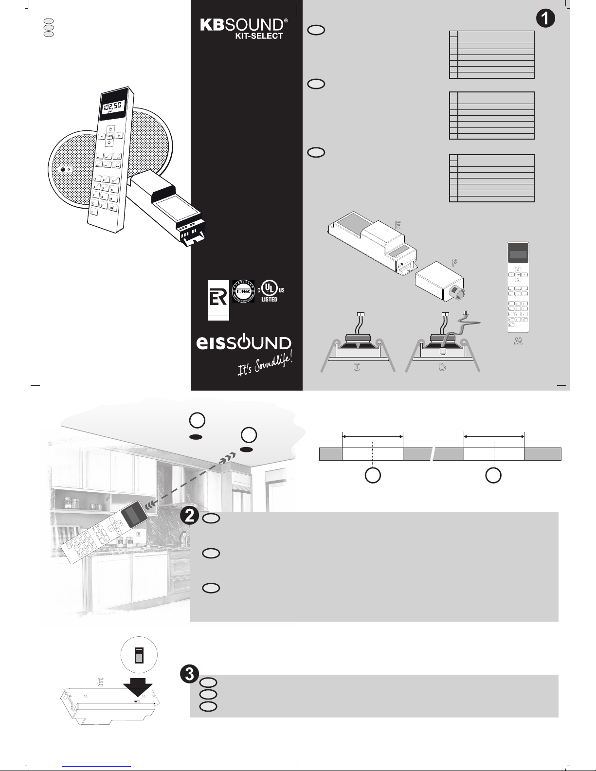
Place loudspeaker and pull the joining cables to the other loudspeaker 's location.I D
Instalar el altavoz llevando los cables de conexión hasta la ubicación del otro altavoz
Introduire le haut-parleur en conduisant les cables de connexion jusqu´à l´emplacement de l´autre
haut-parleur
I D
I
D
ENG
E
F
Connect a wire to antenna termina (A) on control unitl30 in. (76cm)
Conectar un hilo de 30 in. (76cm) a la regleta de antena (A) del módulo de control .
Connecter un fil de 30 in. (76cm) à la réglette de l´antenne (A) du module de contrôle
E
E
E
A 75 ohm antenna signal can be connected to terminals A and M of the control unit if FM
reception unsatisfactory.
Para casos en los que la recepción de emisoras FM sea deficiente puede conectarse una señal de
antena de 75 ohmios a las regletas A y M del módulo de control.
Dans les cas où la reception des émissions FM est insuffisante, on peut connecter un signal
d´antenne de 75 ohms aux réglettes A et M du module de contrôle.
ENG
E
F
+
-
Rojo
Negro
I
D
IRD C
MA I
antenna (30in / 76cm)
+
-
Rojo
Negro
D
+
-
Rojo
Negro
I
ENG
E
F
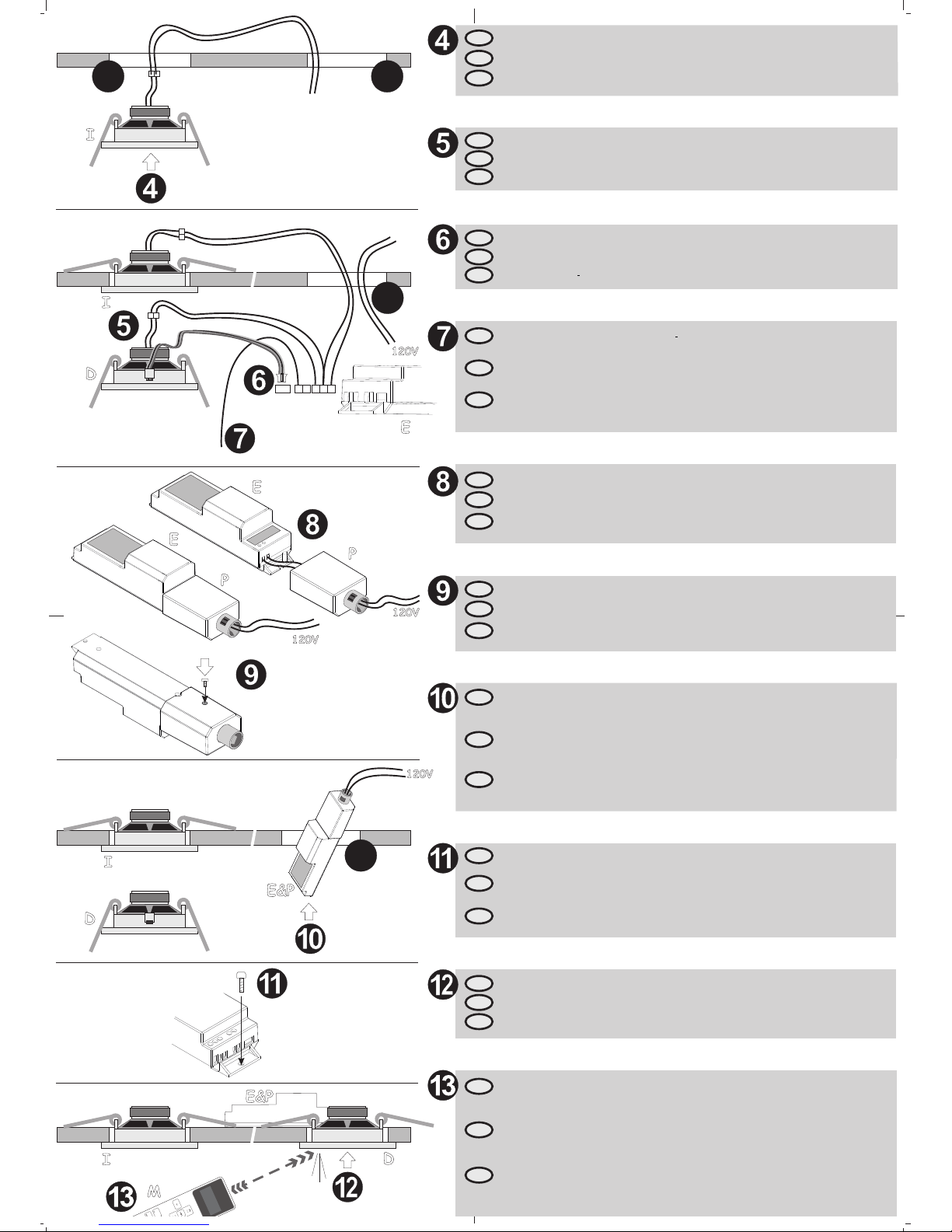
Connect receiver 's cable from speaker to terminal IRD on control unit
Conectar el cable del receptor desde el altavoz al conector IRD del módulo de control
Connecter le cable du récepteur au connecteur IRD du module de contrôle
D E
D E
D E
120V
ENG
E
F
Place control unit joined together with protection box through the cavity prepared for loudspeaker .
Try to keep the antenna cable away from possible noise sources such as fluorescent bulbs, power supplies,
halogen lamps, fans, motors, etc. which could hamper the radio station reception and affect sound
quality.
Introducir el conjunto formado por el módulo de control y la caja de protecci'on por el agujero
preparado para el altavoz . Procurar que el cable de antena quede alejado de fluorescentes, fuentes de
alimentación, lámparas halógenas, ventiladores, motores, etc. que perjudicarán la recepción de emisoras
de radio y afectará a la calidad de sonido.
Introduire le module de contrôle conjointement avec le boîtier de protection dans l´orifice préparé
pour le haut-parleur . Faites de sorte que le cable de l´antenne soit éloigné de toutes possibles sources
de bruit comme les tubes fluorescents, les sources d´alimentation, les lampes halogènes, les ventilateurs,
les moteurs, etc. qui nuisent à la reception des émissions de radio et affectent la qualité du son.
E P D
E P
D
E P
D
ENG
E
F
Pass building wire 120V network line through wire protection box and connect to L and N terminals. Cut
back the ground wire and keep it away from the proximity of L and N terminals
Pasar el cable de red 120V a través de la caja de protección y conectar a los terminales L y N. Cortar el
cable de tierra y mantenerlo alejado de los terminales L y N
Passer le câble de réseau 120V à travers le boîtier de protection et le connecter aux bornes L et N.
Couper le câble de terre et le maintenir éloigné des bornes L et N.
P
P
P
ENG
E
F
I
D
D
E&P
I
Feed power to the installation. The LED on receiver will flicker several times in blue to indicate that the device has
been switched on correctly. At that time, the unit is ready to be operated by remote control unit
.
Suministrar alimentación a 120V a la instalación. El indicador luminoso parpadeará varias veces en color azul
para indicar que el módulo se ha inicializado de manera correcta. A partir de este momento el
está preparado para su manejo utilizando para ello el mando a distancia
Fournir l´alimentation à l´installation. L´indicateur lumineux clignotera plusieurs fois pour indiquer que le module
a commencé à fonctionner correctement. A partir de ce moment le est prêt à être utilisé en
employant la télécommande .
Start-up
Puesta en funcionamiento
®
®
®
M
M
M
kb
kb
kb
sound select
sound select
sound select
Mise en marche
ENG
E
F
Connect loudspeakers and to connecting terminals D, C and I on control unitD I E.
Conectar los altavoces e a las regletas de conexión D, C e I del módulo de control .
Connecter et aux réglettes de connexion D, C et I du module de contrôle
D I E
les haut-parleurs D I E.
ENG
E
F
Join protection box with electronic module and fix them together with the screw supplied
Acoplar la caja protectora con el módulo de electrónica fijándolos con el tornillo suministrado para
tal efecto
Accoupler le boîtier de protection au module d'électronique en les fixant avec la vis fournie à cet effet.
P E
P E
P E
ENG
E
F
Place loudspeaker in its final location.D
Introducir el altavoz en su ubicación definitiva
Introduire le haut-parleur dans son emplacement définitif.
D
D
ENG
E
F
E
E
P
120V
LN
E
P
120V
120V
E&P
M
ID
D
DThe electronic module must be secured to the building structure through the hole indicated in the picture
(5/32" or 4mm diammeter) and the appropiate screw (not supplied).
E
El módulo de electrónica debe ser fijado a la estructura del edificio utilizando para ello el agujero
suministrado a tal efecto utilizando el tornillo adecuado para el material de la estructura donde irá fijado
dicho módulo de electrónica (tornillo no suministrado en el kit, diámetro aconsejado 5/32" ó 4mm) .
5/32"
E
E
Le module d'électronique doit être fixé à la structure du bâtiment, en utilisant pour cela le trou fourni à cet
effet. Utilisez la vis appropriée au matériau de la structure où sera fixé le module d'électronique (diamètre:
, 4 mm.)

Other KBSOUND Stereo System manuals

KBSOUND Premium kit User manual

KBSOUND

KBSOUND Premium kit User manual

KBSOUND Bluetooth User manual

KBSOUND

KBSOUND Bluetooth User manual

Popular Stereo System manuals by other brands

Sanyo DC-D37 Service manual

Sanyo

Sanyo DC-D37 Service manual

Sharp SD-EX220 Operation manual

Sharp

Sharp SD-EX220 Operation manual

Panasonic RX-DS22 operating instructions

Panasonic

Panasonic RX-DS22 operating instructions

Sharp CD-M4000 Operation manual

Sharp

Sharp CD-M4000 Operation manual

Sony HCD-GN660 Service manual

Sony

Sony HCD-GN660 Service manual

LG CJ98 Service manual

LG

LG CJ98 Service manual

Sony HCD-GNV99D Service manual

Sony

Sony HCD-GNV99D Service manual

Sony Giga Juke NAS-SC500PK Setup guide

Sony

Sony Giga Juke NAS-SC500PK Setup guide

Kicker 40iK5 owner's manual

Kicker

Kicker 40iK5 owner's manual

Scott R-316 Service manual

Scott

Scott R-316 Service manual

Victrola VTA-270B instruction manual

Victrola

Victrola VTA-270B instruction manual

IK Multimedia ARC System 2 user manual

IK Multimedia

IK Multimedia ARC System 2 user manual

Sony ZS-BT1 - Boombox With Bluetooth Technology operating instructions

Sony

Sony ZS-BT1 - Boombox With Bluetooth Technology operating instructions

Kurzweil PC88 user manual

Kurzweil

Kurzweil PC88 user manual

Philips SBCHC500/05 Instructions for use

Philips

Philips SBCHC500/05 Instructions for use

Sony CMT-U1 operating instructions

Sony

Sony CMT-U1 operating instructions

Daewoo RD-400 Series Service manual

Daewoo

Daewoo RD-400 Series Service manual

Teac CX-200iDAB owner's manual

Teac

Teac CX-200iDAB owner's manual

manuals.online logo
manuals.online logoBrands
  • About & Mission
  • Contact us
  • Privacy Policy
  • Terms and Conditions

Copyright 2025 Manuals.Online. All Rights Reserved.