Requires an extension kit 13.795, shown to the right.
The principle for operating the piston corer function:
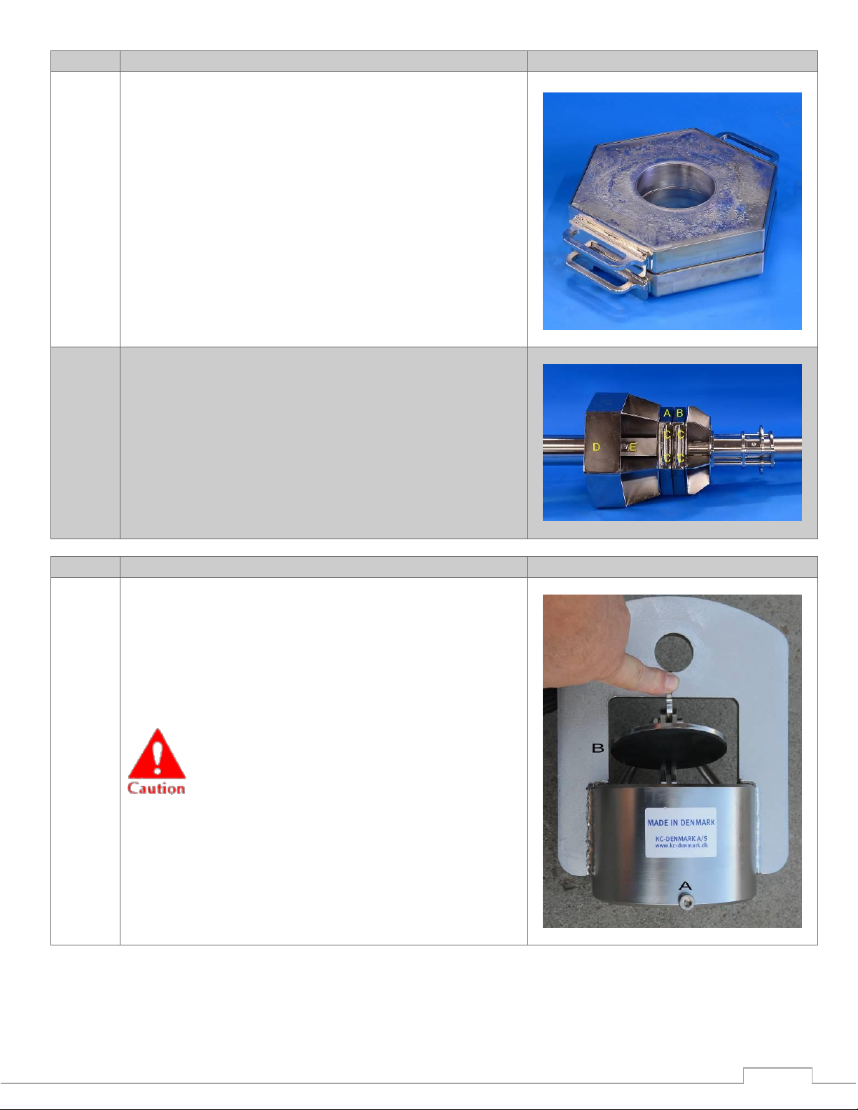
An AISI 316 stainless steel heavy-duty releaser (pos.
1), based on the Kullenberg principle, is mounted at
the top. Up to 20 lead weights (pos. 4) of 80 kg, each
can be added. The upper part of the corer is made of
AISI 316 stainless steel.
The corer tube (pos. 9) is made of AISI 316 stainless
steel (Ø140/Ø130 mm). At the end of the releaser
hook (pos. 1); the 30 kg release weight (pos. 7) is
mounted.
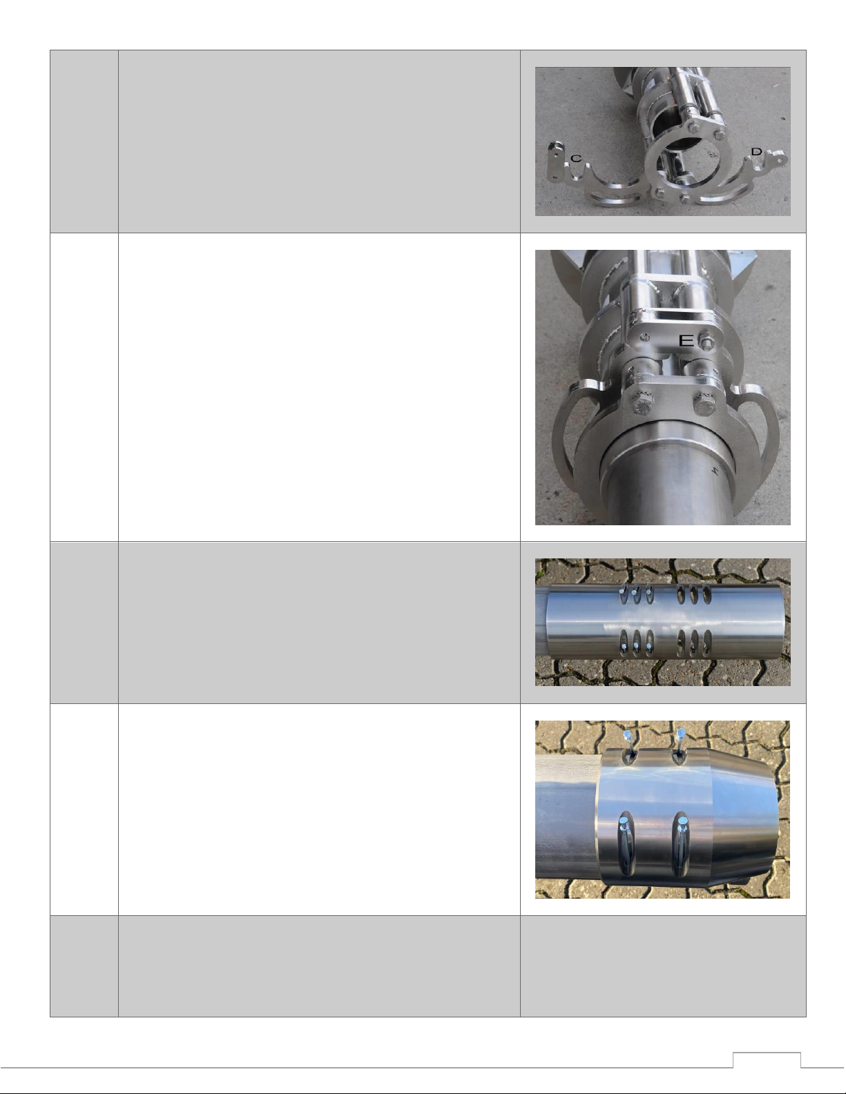
A piston with a leather seal, (pos. 8) is positioned at
the bottom of the corer tube. The piston is connected
to the releaser (pos. 1) by an Ø8 mm stainless steel
AISI 316 steel wire. During the deployment the corer
tube (pos. 9) is released 1,7 meter above the sediment
as the releaser weight reaches the sediment surface.
The wire (pos. 8), which has a slack of about 1 meter,
allows the corer tube to fall free until the piston (pos.
7) is activated just before the corer tube enters the
sediment. The total weight load can regulate the depth
of penetration. (pos. 4).
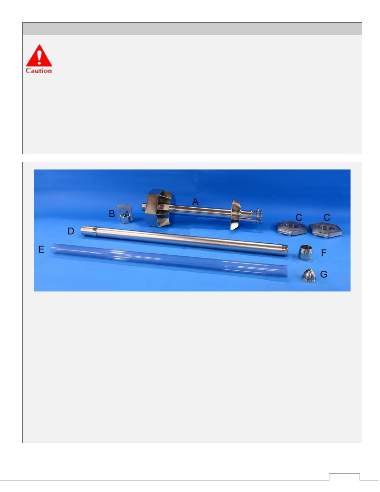
The principle for operating the piston corer function:
1. Kullenberg releaser
2. Wire (Ø8 mm) for piston
3. Steering fins
4. Lead weight
5. Lock for corer tube
6. Wire (Ø5 mm) for Kullenberg releaser and 30 kg
weight station
7. Weight station, 30 kg
8. Piston
9. Corer tube
14. Safety split
NOTE:
When using other lengths of sample tubes, the length
of the two steel wires must be changed accordingly.