manuals.online logo
Brands
  1. Home
  2. •
  3. Brands
  4. •
  5. KE2 Therm Solutions
  6. •
  7. Network Hardware
  8. •
  9. KE2 Therm Solutions 20178 User manual

KE2 Therm Solutions 20178 User manual

Q.1.64 October 2021
KE2 EvaporatorEciency
Condensed Quick Start Guide
thermsolutions
This reference should remain on site
with the installed KE2 Evap controller.
© Copyright 2021 KE2 Therm Solutions, Inc., Washington, Missouri 63090
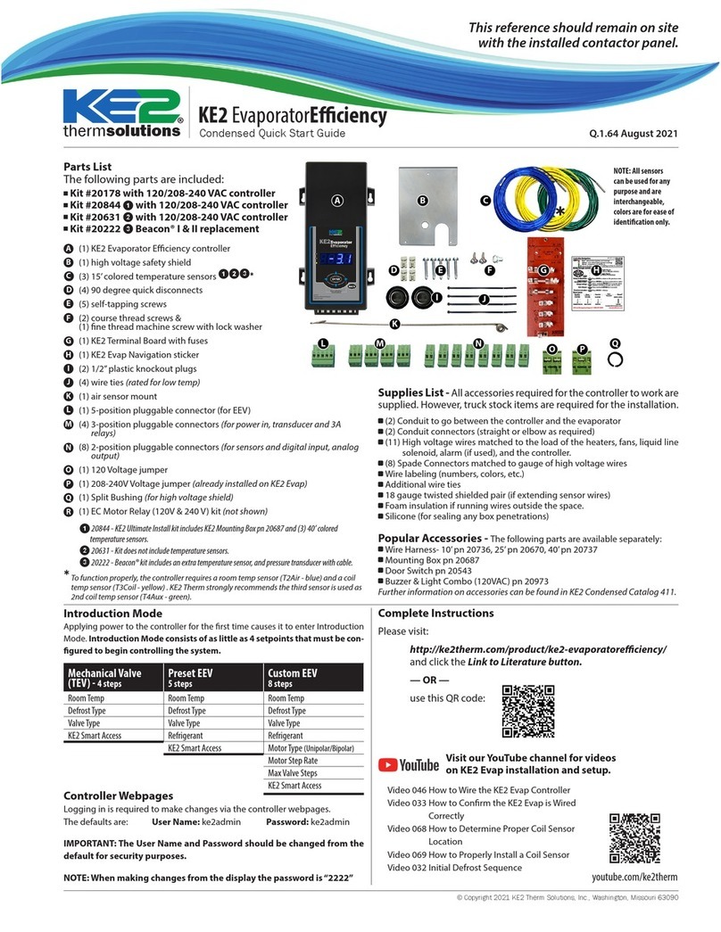
Parts List
The following parts are included:
Kit #20178 with 120/208-240 VAC controller
Kit #20844 ❶with 120/208-240 VAC controller
Kit #20631 ❷with 120/208-240 VAC controller
Kit #20222 ❸Beacon® I & II replacement
(1) KE2 Evaporator Eciency controller
(1) high voltage safety shield
(3) 15’ colored temperature sensors ❶❷❸*
(4) 90 degree quick disconnects
(5) self-tapping screws
(2) course thread screws &
(1) ne thread machine screw with lock washer
(1) KE2 Terminal Board with fuses
(1) KE2 Evap Navigation sticker
(2) 1/2” plastic knockout plugs
(4) wire ties (rated for low temp)
(1) air sensor mount
(1) 5-position pluggable connector (for EEV)
(4) 3-position pluggable connectors (for power in, transducer, and 3A
relays)
(8) 2-position pluggable connectors (for sensors, digital input, and analog
output)
(1) 120 Voltage jumper
(1) 208-240V Voltage jumper (already installed on KE2 Evap)
(1) Split Bushing (for high voltage shield)
(1) EC Motor Relay (120V & 240V) kit (not shown)
❶20844 - KE2 Ultimate Install kit includes KE2 Mounting Box and (3) 40’ colored temp sensors.
❷20631 - Kit does not include temperature sensors.
❸20222 - Beacon® kit includes an extra temperature sensor, and pressure transducer with 10’ cable.
*To function properly, the controller requires an air temp sensor (T2Air - blue) and a coil
temp sensor (T3Coil - yellow) . KE2 Therm strongly recommends the third sensor is used as
2nd coil temp sensor (T4Aux - green).
Supplies List - All accessories required for the controller to work are
supplied. However, truck stock items are required for the installation.
(2) Conduit to go between the controller and the evaporator
(2) Conduit connectors (straight or elbow as required)
(11) High voltage wires matched to the load of the heaters, fans, liquid line
solenoid, alarm (if used), and the controller.
(8) Spade Connectors matched to gauge of high voltage wires
Wire labeling (numbers, colors, etc.)
Additional wire ties
18 gauge twisted shielded pair (if extending sensor wires)
Foam insulation if running wires outside the space.
Silicone (for sealing any box penetrations)
Popular Accessories - The following parts are available separately:
Wire Harness- 10’pn 20736, 25’pn 20670, 40’pn 20737
Mounting Box pn 20687
Door Switch pn 20543
Buzzer & Light Combo (120VAC) pn 20973
Further information on accessories can be found in KE2 Condensed Catalog 411.
A
C
D
E
F
G
H
I
J
K
L
M
N
B
O
P
L M N
DE
OP
F
B
Left Arrow & Right Arrow
Use to move between Menuscolumns
Up Arrow & DownArrow
Scroll through Menu Parameters
ENTER
Press and hold ENTER for 3 seconds, when
display is blinking changes can be made.
BACK
Press BACKto return to the previous view.
Press and hold ENTER for3 seconds.
Change settings:
Savechanges:
Moving throughcontroller menus:
Returnto Main Menu:
Lights: Red - critical alarm (system not running)
Yellow- non-critical alarm (system running)
Green - compressor should be on
- compressor waiting on timer to start/stop
ENTER
Press ENTER to go fromparameter to value.
Togglebeween
description& value :
Menu Layout:
Variables Manual*
(viewonly)
Alarms
(viewonly)
ENTER
Setpoints Enter
Password
NOALARM
EMAILFAILURE
ROOMTEMP
DERIVATIVE
ROOMTEMP
FIRMWAREVERSION
MANUALCONTROL
CLEARMD
Controller Navigation
ENTER
ENTER
BACK
Press BACK3 - 4 times
Ifyou lose your place:
*For manual defrost use MANUAL CONTROL
BACK
24-hour Emergency Support: 1.888.337.3358 www.ke2therm.com
pn21061 9-14
AC
G H
IJ
K
Q
NOTE: All sensors
can be used for any
purpose and are
interchangeable,
colors are for ease of
identication only.
Video 046 How to Wire the KE2 Evap Controller
Video 033 How to Conrm the KE2 Evap is Wired
Correctly
Video 068 How to Determine Proper Coil Sensor
Location
Video 069 How to Properly Install a Coil Sensor
Video 032 Initial Defrost Sequence
Visit our YouTube channel for videos
on KE2 Evap installation and setup.
Introduction Mode
The controller will enter Introduction Mode the rst time power is applied.
Introduction Mode consists of as little as 4 setpoints that must be congured
to begin controlling the system.
Mechanical Valve
(TEV) - 4 steps
Preset EEV
5 steps
Custom EEV
8 steps
Room Temp Room Temp Room Temp
Defrost Type Defrost Type Defrost Type
Valve Type Valve Type Valve Type
KE2 Smart Access Refrigerant Refrigerant
KE2 Smart Access Motor Type (Unipolar/Bipolar)
Motor Step Rate
Max Valve Steps
KE2 Smart Access
Complete Instructions (Q.1.3)
Please visit:
http://ke2therm.com/product/ke2-evaporatoreciency/
and click the Link to Literature button.
— OR —
use this QR code:
youtube.com/ke2therm
*
Q
R
Controller Webpages
Logging in is required to make changes via the controller webpages.
The defaults are: User Name: ke2admin Password: ke2admin
IMPORTANT: The password MUST be changed from the default for secu-
rity purposes.
NOTE: When making changes from the display the password is“2222”
© Copyright 2021 KE2 Therm Solutions, Inc., Washington, Missouri 63090
Q.1.64 October 2021
Page 2
KE2 EvaporatorEciency
Condensed Quick Start Guide
BL/BK
OR/BK
Y/BK
FAN/S
HEATERS
LL SOLENOID/COMP RELAY
BK/OR
L1
WT/R
L2
HS
GND
P/N 20996
12 AMP
20 AMP
3 AMP
OR NEUTRAL
HEATERS
thermsolutions
®
NO NC
COM
NO NC
COM
COM NC
NO
COM
NC
N0
Solenoid Relay
Defrost
Relay
Fan
Relay
208-240
Power Input
Voltage Jumper
208-240 Default
L1
Ground
L2
COM NC
NO
COM
NC
N0
Auxiliary Relay
Yellow with black stripe 16 AWG
Black with yellow stripe (L1) 16 AWG
Blue with black stripe 14 AWG
Black with blue stripe (L1) 14 AWG
LLS/Compressor
Fans
Black with white (L1) 16 AWG
White with red (L2/neutral) 16 AWG
Green (Ground) 16 AWG
Power
Orange with black stripe 12 AWG
Black with Orange stripe (L1) 12 AWG
Defrost Heaters
Supply Voltage
FAN
MOTOR
FAN
MOTOR
FAN
MOTOR
EVAPORATOR
FANS
HEATER LIMIT SWITCH
DEFROST HEATERS
LIQUID LINE SOLENOID
N.C.
R/W
BL/BK
BK
BL/BK
FROM
CONTROLLER
EC MOTOR
RELAY
See Q.1.30 Figure 3 for wiring
of the EC Motor Relay.
DI 1
DI 3
DI 2
door switch
system o
dual temp setting
external alarm
light switch
defrost interlock
defrost lockout
Digital Inputs
KE2 RSV
blue
orange
yellow
red
black
RJ45 Ethernet Connection
Temperature Sensors
Pressure
Transducer
T1SuctT4Aux T2AirT3Coil
green
red
black
Temperature Sensors (4) Pressure Transducer
ground
signal +5
Pressure Transducer
Wiring Detail
black
red
green
0-10V analog out for variable speed fans
+
_
Part Number 20222
Beacon replacement
controller required for
Beacon® I & II valves.
EEV Input
Liq. Line Solenoid Relay
LLS/Compressor Contactor
Wiring Schematic - Controller New Installation
For step-by-step wiring instructions see Q.1.3 KE2 Evap Quickstart Guide
Wiring Schematic - Controller New Installation
Q
Use Split Bushing ("Q" in the kit) to
prevent chang of the high volt-
age wires if routing through the
high voltage shield
© Copyright 2021 KE2 Therm Solutions, Inc., Washington, Missouri 63090
Q.1.64 October 2021
Page 3
KE2 EvaporatorEciency
Condensed Quick Start Guide
Diagnostic Test
After Intro Mode the KE2 Evap will scroll START DIAGNOSTIC TEST. The optional
Diagnostic Test helps conrm wiring is correct. Check that all system components
are o, then press and hold ENTER to start, or press
BACK
to skip the test.
In Diagnostic Mode the KE2 Evap will energize and de-energize each relay one at
a time to allow you to conrm that only the correct component is running. The
order is FAN RELAY, DEFROST RELAY (except air defrost), AUX RELAY, LLS RELAY.
When prompted by the display, conrm whether the relevant component is ON or
OFF. Press ENTER to proceed to the next step, or wait 2 minutes for the controller
to proceed to the next step automatically. During the LLS RELAY test, the EEV will
control to superheat and fans will turn on after 1 minute to prevent oodback.
Adjusting Controller Parameters
The Controller Navigation illustration on pg. 4 shows the controller menu struc-
ture. The default display of the controller shows actual room temperature, defrost,
or any alarm condition. Press or to move from the default display to the
next menu column. The VARIABLES menu column consists of the current sensor
readings, and the relay states. The MANUAL menu column allows manual control
of the EEV, relays, and contains network setpoints. The SETPOINTS menu column
contains all refrigeration and remaining setpoints.
The controller will display LOGIN when the user attempts to access the
SETPOINTS or MANUAL menu. The User Password (1111) provides access to the
ROOM TEMP setpoint. Access to the full SETPOINTS or MANUAL menu requires
the Installer Password (2222).
Press
BACK
at any time to return to the next level up in the menu. A second/third
press will return to the default display.
Controller Setup: Intro Mode
The controller enters Intro Mode the rst time power is applied, which consists
of as little as 4 setpoints that must be congured to begin controlling the system.
Step ❶- The rst setpoint to enter is ROOM TEMP. The default is 0.0ºF, and the
right most 0 will be ashing. Use and to change the digit being modied.
Press to raise the temp, and to lower the temp. Once you have the desired
room temp, press and hold ENTER for three seconds.
Step ❷- Next, DEFROST TYPE then ELEC (electric) will be displayed. The con-
troller is designed to work with electric, hot gas, and air defrost. Press or to
select the correct defrost type, then press and hold ENTER for three seconds.
Step ❸- VALVE TYPE then MECHANICAL will be displayed. If the expansion
valve is mechanical (TEV), press and hold ENTER for three seconds. If you have
an electric expansion valve (EEV), use or to navigate to the correct valve
model. With the correct EEV displayed, press and hold ENTER for three seconds.
NOTE: If an EEV is selected, you will be prompted to specify the REFRIGERANT.
The KE2 Evap may also be applied with user-dened CUSTOM EEVs. When CUS-
TOM is selected, the user is also prompted to select MOTOR TYPE, MOTOR STEP
RATE, and MAX VALVE STEPS.
Step ❹- The fourth prompt is whether KE2 SMART ACCESS is ENABLED or
DISABLED. KE2 SMART ACCESS allows you to view your controller online. Make
your selection by using or then press and hold ENTER for three seconds.
These are the only setpoints required to begin controlling the system. For setup
with multi-evaporator applications see bulletins Q.5.10 and Q.1.32
Install the air temp sensor using the air sensor mount K, approximately 2/3 down from the top
of the evaporator, and 8 - 12 inches from coil in the return air of the evaporator.
IMPORTANT: Determine the coil sensor location
When arriving on site, put the system into defrost and observe where frost is last to disap-
pear on the coil. Place one sensor in each of the last two places where frost disappears ❶.
Monitor the evaporator’s air entering and exiting sides. Often the last place frost disappears is
on the air exiting side, near the right or left end.Verify all heating elements are working properly.
Sensor location is often approximately 1 to 1-1/2” away from the right and left edges of the ac-
tive coil surface, near the top or bottom 1/3rd of the evaporator, as far away from the defrost
heat sources as possible. Ice tends to grow from the edges inward, but verify coil sensor loca-
tions by observing an actual defrost. Do not install coil sensor on the U-bends.
Note: To prevent sensor wire damage from sharp edges, insert plug Iinto coil housing - ❷.
Plug is inserted in the inner housing to access the coil. Puncture plug to insert sensor wire.
The sensor should touch two circuit tubes ❸. When inserting the sensor into the coil, the tip
should touch one of the circuit tubes. Don’t locate it next to the heating elements. In ❹the
probe is inserted into the ns approximately 1/16” deeper than the stainless shielding. Pinch
the ns gently together, securing the sensor. This also provides thermal ballast, ensuring a com-
plete defrost.
Alternate method - As the defrost termination sensor, it is critical the sensor does not termi-
nate defrost before all frost is removed from the coil. In some installations, inserting the sensor
into the coil may position it too close to the defrost heat source. An alternate method of po-
sitioning places the sensor vertically between the coil ns, see ❺. Pinch ns together gently,
securing the sensor.
Extending sensor wires
After the sensors are mounted, route them back to the controller. If the wires must be ex-
tended, use 18 gauge twisted shielded pairs. Max recommended length for 18 gauge: 100ft.
When running the wires back to the controller, do not induce noise on the sensor wires. This
occurs when sensor wires are located near high voltage lines (dened by UL as greater than
30V). Do not run high voltage and low voltage wires in the same conduit.
If crossing a high voltage line, run the sensor wiring at right angles to minimize noise.
Verify where frost is last to
disappear by initiating a defrost,
and observing last spots to clear.
Verify where frost is
last to disappear
(often on air exiting side).
Item Ifrom Parts List on page 1
❶
❷
❺
❹❸
© Copyright 2021 KE2 Therm Solutions, Inc., Washington, Missouri 63090
Q.1.64 October 2021
Page 4
KE2 EvaporatorEciency
Condensed Quick Start Guide
Q.1.64 October 2021 supersedes all prior publications KE2 Therm Solutions
12 Chamber Dr. . Washington, MO 63090
636-266-0140 . www.ke2therm.com
NO ALARM
PRESSURE SENSOR
SUCTION TEMP SENSOR
AIR TEMP SENSOR
COIL TEMP SENSOR
AUX TEMP SENSOR
HIGH SUPERHEAT
LOW SUPERHEAT
HIGH AIR TEMP
LOW AIR TEMP
EXCESS DEFROST
DEFR TERM ON TIME
DOOR SWITCH
COMMUNICATION ERROR
EXT ALARM
EMAIL FAILURE
HELP
TIME SERVER COMM
Alarms
(view only)
Variables
(view only)
Non-adjustable
ROOM TEMP
COIL TEMP
SYSTEM MODE
SUPERHEAT
SUCTION PRESSURE
T1 SUCTION TEMP1
SATURATION TEMP
VALVE % OPEN4
T4 AUX TEMP1
LLS RELAY
DEFROST RELAY
FAN RELAY
AUX RELAY
DIG 1 STATUS
DIG 2 STATUS
DIG 3 STATUS
IP OCTET 1
IP OCTET 2
IP OCTET 3
IP OCTET 4
SUBNET MASK OCTET 1
SUBNET MASK OCTET 2
SUBNET MASK OCTET 3
SUBNET MASK OCTET 4
FIRMWARE PART NO
FIRMWARE VERSION
1 T1 & T4 are parameters
and can be set to various
functions. The default for
T1 is Suction Temp, the
default for T4 is Coil Temp.
2 The Setpoint paramenters
shown in BOLD (Valve
Type, Room Temp
Setpoint and Defrost
Mode) need to be set by
the user prior to start up.
The other Setpoint
Parameters can also be
adjusted, however, the
factory setpoints are
generally correct for most
applications.
3 The Setpoint parameters
shown in ITALIC are
displayed only when a
Custom EEV is used.
4 Displayed when an EEV is
used.
5 Only available if mechani-
cal valve is selected. When
using an electric valve T1
is xed as suction
temperature.
6 The Setpoint parameters
shown in BOLD ITALIC are
active for bonded
controllers only.
7 Only displayed when Run
Time Defrost is selected.
Setpoints
ROOM TEMP2
DEFROST TYPE2
VALVE TYPE2
MOTOR TYPE3
MOTOR STEP RATE3
MAX VALVE STEPS3
MAX SUPERHEAT ALARM/SUPERHEAT4
MAX OPERATING PRES4
REFRIGERANT
AUX TEMP 4 MODE
AUX TEMP 1 MODE5
AUX RELAY MODE
FAN SPEED
MAX FAN SPEED
MIN COMP RUN TIME
MIN COMP OFF TIME
REFRIG FAN MODE
DEFROST MODE
DEFROSTS / DAY
1ST DEFROST DELAY
DEFROST FAN STATE
DEFROST TERM TEMP
DEFROST PARAMETER/MAX DEFROST TIME
DRAIN TIME
COMP RUN TIME7
ELEC DEFROST MODE
FAN DELAY TEMP
MIN FAN SWITCH TIME
MAX FAN DELAY TIME
PUMP DOWN TIME
MULTI AIR TEMP CTRL
MULTI EVAP COOL6
MULTI EVAP DEFROST 6
MULTI EVAP SENSOR6
ROOM TMP IND DEF
HIGH TEMP ALARM OFFSET
HIGH TEMP ALARM DELAY
LOW TEMP ALARM OFFSET
LOW TEMP ALARM DELAY
DOOR ALARM DELAY
DIG IN 1 MODE
DIG IN 1 STATE
DIG IN 2 MODE
DIG IN 2 STATE
DIG IN 3 MODE
DIG IN 3 STATE
2ND ROOM TEMP
SUCT PRES OFFSET
SUCT TEMP OFFSET
AIR TEMP OFFSET
COIL TEMP OFFSET
AUX TEMP OFFSET
TEMP UNITS
BRIGHTNESS
AIR TEMP DIFF
EXTREME TEMP DIFF
PROPORTIONAL
INTEGRAL
DERIVATIVE
Options for
DIG IN STATUS
DISABLED
2ND (ROOM) TEMP
DOOR SWITCH
EXT ALARM
SYSTEM OFF
LIGHT SWITCH
DEFROST LOCKOUT
DEFROST INTERLOCK
Login/
Logout
MANUAL CONTROL
MANUAL VALVE4
CLEAR ALARMS
TEST LLS RELAY
TEST DEFROST RELAY
TEST FAN RELAY
TEST AUX RELAY
START DIAGNOSTIC TEST
FACTORY RESET
WEB PASSWORD RESET
SMART ACCESS MODE
DHCP MODE
BOND
DOD INIT
Manual
Menu
Parameters:
Menu
Columns:
ENTER
ENTER
Left & Right arrows move
between Menus
Up & Down arrows scroll
through Menu Parameters
ENTER
Press ENTER, when display
is blinking, changes
can be made
BACK
Press BACK to return to
the previous view.
ENTER
Press & hold ENTER for
3 seconds to save change
Change settings:
Save setting
changes:
Move through
menus:
Return to
Main Menu:
Indicator Lights
Red - critical alarm
Yellow - non-critical alarm
Green - calling for refrigeration (LLS relay energized)
Green ashing - waiting on min. run or min. o
time to start/stop refrigeration
ENTER
Press ENTER to go from
parameter to value.
View parameter
value :
Navigating Menus - When making changes from the display the password is “2222”

This manual suits for next models

3

Other KE2 Therm Solutions Network Hardware manuals

KE2 Therm Solutions KE2 Evaporator Efficiency User manual

KE2 Therm Solutions

KE2 Therm Solutions KE2 Evaporator Efficiency User manual

KE2 Therm Solutions KE2 Local AreaDashboard & Alarms Manual

KE2 Therm Solutions

KE2 Therm Solutions KE2 Local AreaDashboard & Alarms Manual

KE2 Therm Solutions KE2-EM35 Manual

KE2 Therm Solutions

KE2 Therm Solutions KE2-EM35 Manual

Popular Network Hardware manuals by other brands

Polycom V2IU5300-S brochure

Polycom

Polycom V2IU5300-S brochure

Atlantis Land DiskMaster NASG302D quick start guide

Atlantis Land

Atlantis Land DiskMaster NASG302D quick start guide

evertz 7700 Series manual

evertz

evertz 7700 Series manual

Dot Origin VTAP100 installation guide

Dot Origin

Dot Origin VTAP100 installation guide

Belkin IEEE 1394 PCMCIA CARDBUS user manual

Belkin

Belkin IEEE 1394 PCMCIA CARDBUS user manual

Mobatime DTS 2440.audio-clock instruction manual

Mobatime

Mobatime DTS 2440.audio-clock instruction manual

Nortel 6000 Series manual

Nortel

Nortel 6000 Series manual

Planet WBS-512AC user manual

Planet

Planet WBS-512AC user manual

ActiveEye K9504L-W Operation manual

ActiveEye

ActiveEye K9504L-W Operation manual

HIK VISION BCS-V-NVRXX02-4K Series user manual

HIK VISION

HIK VISION BCS-V-NVRXX02-4K Series user manual

DVR SYSTEMS Network Video Recorder user manual

DVR SYSTEMS

DVR SYSTEMS Network Video Recorder user manual

FOR-A USF-105PS Operation manual

FOR-A

FOR-A USF-105PS Operation manual

X-Vision X2RN user guide

X-Vision

X-Vision X2RN user guide

HIK VISION HiWatch Series user manual

HIK VISION

HIK VISION HiWatch Series user manual

Tripp Lite SmartRack SR42UBEXPKD Assembly instructions

Tripp Lite

Tripp Lite SmartRack SR42UBEXPKD Assembly instructions

IPEX PH232Ex1Plus user manual

IPEX

IPEX PH232Ex1Plus user manual

HIK VISION HWN-2104H-4P user manual

HIK VISION

HIK VISION HWN-2104H-4P user manual

Watchguard Transfer Station II quick start guide

Watchguard

Watchguard Transfer Station II quick start guide

manuals.online logo
manuals.online logoBrands
  • About & Mission
  • Contact us
  • Privacy Policy
  • Terms and Conditions

Copyright 2025 Manuals.Online. All Rights Reserved.