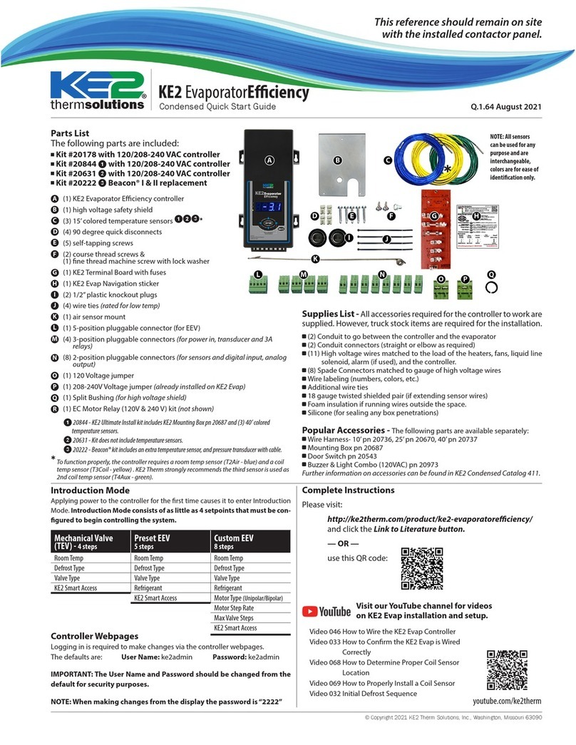
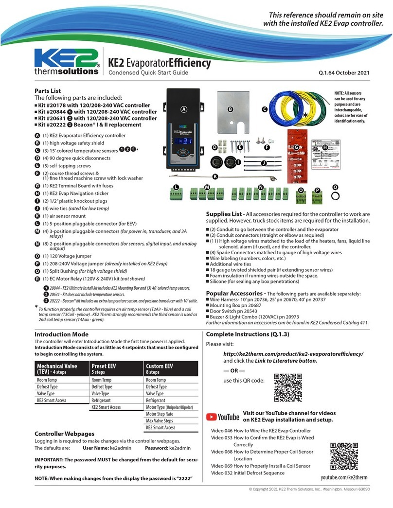
KE2 Therm Solutions KE2 Local AreaDashboard & Alarms Manual

KE2 Therm’s Local Area Dashboard & Alarms (LDA) is the per-
fect addition to the Refrigeration Network. When the KE2
LDA is connected to the same network as KE2 Therm control-
lers, it immediately and automatically scans and finds all KE2
Therm controllers –Ethernet or Serial-ModBus.
Serve as a Permanent WiFi Service Tool
Display a Local Area Dashboard showing controllers connected to the cus-
tomer’s network
Connect controllers to KE2 SmartAccess customer portal without requiring
controller upgrades
Send Email Alarms to multiple email recipients
View Serial devices in a webpage, make changes to setpoints, and receive
alerts via email or text message
366-day datalogging when used with the KE2 Flash Drive (see bulletin Q.5.48)
Create a Wireless Bridge to the local network (Wirelessly connect a control-
ler to existing WiFi - Not available in the first release.)
The KE2 LDA allows customers to locally view all of their controllers in a single view,
without a recurring fee. And, additionally, enables customers to access their control-
lers over the Internet, by functioning as a conduit to KE2 SmartAccess (available for a
nominal monthly charge.)
© Copyright 2016 KE2 Therm Solutions, Inc., Washington, Missouri 63090
Q.5.42
November 2016
Contents:
Introduction, Features & Benets - Page 1
KE2 LDA Kit Contents - Page 1
Back Label Information - Page 1
Side View of KE2 LDA - WiFi ON/OFF - Page 1
Installing the KE2 LDA - Pages 2-4
Option 1 Connect Using the KE2 LDA as a
Permanent WiFi Service Tool
Option 2 - Connect Serial Devices Only
Option 3 - Connect Direct to PC via Cable or WiFi
Option 4 - Connect to PC WithoutWiFi to Manage
the KE2 LDA
Option 5 - Connect to WiFi
Using the KE2 Flash Drive - for Data Logging
the KE2 LDA
Access the Local Dashboard - Page 5
Manage Email Alerts - Page 6-7
Credentials: Changing User name & Password
- Page 8
ModBus-Serial Access - Page 9-10
Field Update Process - Page 11
Allowing KE2 Therm Remote Access - Page 12
Remote Access Setup - Page 13-14
Appendix A ModBus Conguration - Page 15-16
Appendix B ModBus Wiring - Page 16
KE2 Local AreaDashboard & Alarms
Overview, Installation, and Setup Instructions V1.1.5 pn 21253
Connecting up to 10 KE2 Therm controllers in one view, and
letting you access and control each individual device.
KE2 LDA Kit (pn 21253) includes the KE2 LDA & Accessories
Power Plug USB CableKE2 LDA 5ft Ethernet CableSerial Adaptor
KE2 LDA Back Label
MAC: EF:95:6E:40:87:F3
WIFI ESSID: KE2LDA-4087F3
WIFI PW: 3YzliZmQyZTI4
MGMT LOGIN: ke2admin
MGMT PW: 3YzliZmQyZTI4
http:ke2lda or IP: 192.168.50.1
Serial #:
16197-251 Power: 5V-1A
Unique for
each LDA QR Code
Links to
Setup Page
Used to
identify
device
KE2 LDA Side View
USB Reset
WiFi Switch
ONOFF

Installing the KE2 LDA: Option 2
Connecting Serial Devices Only
EACH DEVICE MUST HAVE A SEPARATE/
UNIQUE MODBUS ADDRESS
(See Appendix B for instructions)
Connect Customer Network
STATUS
All Clear
Evaporator Fan
Off
Plug power cable into the KE2 LDA
and the other end into an electrical outlet.
The unit will power on automatically.
Connect wirelessly
to the LDA Network
ABC Contracting
(888)555-3358
System Mode
Cool
Superheat
0.0 F Suct Pressure
96.2 F Suct Temp
87.7 F
WAN
Power
LAN
MODIFY STATUS
ABC Contracting
(888)555-3358
All Clear
Compressor
On
System Mode
Cool Evaporator Fan
Off
Room Temp
-8.5 F Coil Temp
15.4 F
Sat Temp
46.0 F
Superheat
0.0 F Valve Position
Manual
Suct Pressure
96.2 F Suct Temp
87.7 F
Dig Input 3
Dis
Defrost
Off Aux Temp
Dis
Dig Input 1
Closed Dig Input 2
Dis
WiFi to PC/Laptop,
Tablet, Phone
Serial-Modbus Controllers:
KE2 Temp, KE2 Low Temp
KE2 Adaptive Control
.
Holdfor manual defrost
thermsolutions
KE2 Temp
Holdfor manual defrost
thermsolutions
KE2 Temp
.
Q.5.42 November 2016
Page 2
KE2 Local AreaDashboard & Alarms
Overview, Installation, and Setup Instructions
© Copyright 2016 KE2 Therm Solutions, Inc., Washington, Missouri 63090
Connect Customer Network
All Clear
Evaporator Fan
Off
Connect wirelessly
to the LDA Network
ABC Contracting
(888)555-3358
System Mode
Cool
Superheat
0.0 F Suct Pressure
96.2 F Suct Temp
87.7 F
WAN
Power
LAN
.
KE2 EvaporatorEfficiency
TM
thermsolutions
ENTER
BACK
.
KE2 EvaporatorEfficiency
TM
thermsolutions
ENTER
BACK
.
Ethernet Controllers:
KE2 Evaporator Eciency,
KE2 Evap for Rack Eciency,
KE2 Controlled Environment
NOTE: DHCP or Static IP in
Customer Network
Plug power cable into the KE2 LDA
and the other end into an electrical outlet.
The unit will power on automatically.
KE2 EvaporatorEfficiency
TM
thermsolutions
ENTER
BACK
.
WiFi to PC/Laptop,
Tablet, Phone
Serial-Modbus Controllers:
KE2 Temp, KE2 Low Temp
KE2 Adaptive Control
.
Holdfor manual defrost
thermsolutions
KE2 Temp
Holdfor manual defrost
thermsolutions
KE2 Temp
.
•KE2 Evaporator Eciency, KE2 Evap for Rack Eciency,
or KE2 Controlled Environment
•DHCP Enabled or set address from
192.168.50.2 to 192.168.50.99
•Check IP address from front panel if DHCP
•Factory assigned 10.10.x.x addresses are now visible when
connected to the LAN port. However, 10.10.x.x controllers can
only be managed by PC, phone, or tablet when wirelessly
connected to the KE2 LDA.
Installing the KE2 LDA: Option 1
Connecting Using the KE2 LDA as a
Permanent WiFi Service Tool
EACH DEVICE MUST HAVE A SEPARATE/
UNIQUE MODBUS ADDRESS
(See Appendix B for instructions)

Installing the KE2 LDA: Option 3
Connection Direct to PC via Cable or WiFi
EACH DEVICE MUST HAVE A SEPARATE/
UNIQUE MODBUS ADDRESS
(See Appendix B for instructions)
Q.5.42 November 2016
Page 3
© Copyright 2016 KE2 Therm Solutions, Inc., Washington, Missouri 63090
KE2 Local AreaDashboard & Alarms
Overview, Installation, and Setup Instructions
Installing the KE2 LDA: Option 4
Connection to PC Without WiFi to
Manage the KE2 LDA
EACH DEVICE MUST HAVE A SEPARATE/
UNIQUE MODBUS ADDRESS
(See Appendix B for instructions)
Connect Customer Network
Plug power cable into the KE2 LDA
and the other end into an electrical outlet.
The unit will power on automatically.
WAN
Power
LAN
.
KE2 EvaporatorEfficiency
TM
thermsolutions
ENTER
BACK
.
MODIFY STATUS
ABC Contracting
(888)555-3358
All Clear
Compressor
On
System Mode
Cool Evaporator Fan
Off
Room Temp
-8.5 F Coil Temp
15.4 F
Sat Temp
46.0 F
Superheat
0.0 F Valve Position
Manual
Suct Pressure
96.2 F Suct Temp
87.7 F
Dig Input 3
Dis
Defrost
Off Aux Temp
Dis
Dig Input 1
Closed Dig Input 2
Dis
KE2 EvaporatorEfficiency
TM
thermsolutions
ENTER
BACK
.
Ethernet Controllers:
KE2 Evaporator Eciency,
KE2 Evap for Rack Eciency,
KE2 Controlled Environment
NOTE: DHCP or Static IP in
Customer Network
Serial-Modbus Controllers:
KE2 Temp, KE2 Low Temp
KE2 Adaptive Control
.
Holdfor manual defrost
thermsolutions
KE2 Temp
Holdfor manual defrost
thermsolutions
KE2 Temp
.
Connect Customer Network
STATUS
All Clear
Evaporator Fan
Off
Plug power cable into the KE2 LDA
and the other end into an electrical outlet.
The unit will power on automatically.
Connect wirelessly
to the LDA Network
ABC Contracting
(888)555-3358
System Mode
Cool
Superheat
0.0 F Suct Pressure
96.2 F Suct Temp
87.7 F
WAN
Power
LAN
.
KE2 EvaporatorEfficiency
TM
thermsolutions
ENTER
BACK
.
MODIFY STATUS
ABC Contracting
(888)555-3358
All Clear
Compressor
On
System Mode
Cool Evaporator Fan
Off
Room Temp
-8.5 F Coil Temp
15.4 F
Sat Temp
46.0 F
Superheat
0.0 F Valve Position
Manual
Suct Pressure
96.2 F Suct Temp
87.7 F
Dig Input 3
Dis
Defrost
Off Aux Temp
Dis
Dig Input 1
Closed Dig Input 2
Dis
KE2 EvaporatorEfficiency
TM
thermsolutions
ENTER
BACK
.
Ethernet Controllers:
KE2 Evaporator Eciency,
KE2 Evap for Rack Eciency,
KE2 Controlled Environment
NOTE: DHCP or Static IP in Customer Network
WiFi to PC/Laptop,
Tablet, Phone
Serial-Modbus Controllers:
KE2 Temp, KE2 Low Temp
KE2 Adaptive Control
.
Holdfor manual defrost
thermsolutions
KE2 Temp
Holdfor manual defrost
thermsolutions
KE2 Temp
.

Q.5.42 November 2016
Page 4
KE2 Local AreaDashboard & Alarms
Overview, Installation, and Setup Instructions
© Copyright 2016 KE2 Therm Solutions, Inc., Washington, Missouri 63090
Installing the KE2 LDA: Option 5
Connection via WiFi
EACH DEVICE MUST HAVE A SEPARATE/
UNIQUE MODBUS ADDRESS
(See Appendix B for instructions)
KE2 Switch to LAN
KE2 EvaporatorEfficiency
TM
thermsolutions
ENTER
BACK
.
KE2 EvaporatorEfficiency
TM
thermsolutions
ENTER
BACK
.
Connect Customer Network
STATUS
All Clear
Evaporator Fan
Off
Plug power cable into the KE2 LDA
and the other end into an electrical outlet.
The unit will power on automatically.
Connect wirelessly
to the LDA Network
ABC Contracting
(888)555-3358
System Mode
Cool
Superheat
0.0 F Suct Pressure
96.2 F Suct Temp
87.7 F
WAN
Power
LAN
.
KE2 EvaporatorEfficiency
TM
thermsolutions
ENTER
BACK
.
KE2 EvaporatorEfficiency
TM
thermsolutions
ENTER
BACK
.
Ethernet Controllers:
KE2 Evaporator Eciency,
KE2 Evap for Rack Eciency,
KE2 Controlled Environment
NOTE: DHCP or Static IP in Customer Network
WiFi to PC/Laptop,
Tablet, Phone
Serial-Modbus Controllers:
KE2 Temp, KE2 Low Temp
KE2 Adaptive Control
.
Holdfor manual defrost
thermsolutions
KE2 Temp
Holdfor manual defrost
thermsolutions
KE2 Temp
.
•KE2 Evaporator Eciency, KE2 Evap for
Rack Eciency,
or KE2 Controlled Environment
•DHCP Enabled or set address from
192.168.50.2 to 192.168.50.99
•Check IP address from front panel if DHCP
•Factory assigned 10.10.x.x addresses are
now visible when connected to the LAN
port. However, 10.10.x.x controllers can
only be managed by PC, phone, or tablet
when wirelessly connected to the KE2 LDA
or hardwired to the KE2 Switch.
Using the KE2 Flash Drive for Data Logging
the KE2 LDA
(See bulletin Q.5.48 for more on the KE2 Flash Drive)
Connect customer
Network to WAN
WAN
Power
LAN
.
KE2 EvaporatorEfficiency
TM
thermsolutions
ENTER
MODIFY STATUS
ABC Contracting
(888)555-3358
All Clear
Compressor
On
System Mode
Cool Evaporator Fan
Off
Room Temp
-8.5 F Coil Temp
15.4 F
Sat Temp
46.0 F
Superheat
0.0 F Valve Position
Manual
Suct Pressure
96.2 F Suct Temp
87.7 F
Dig Input 3
Dis
Defrost
Off Aux Temp
Dis
Dig Input 1
Closed Dig Input 2
Dis
KE2 EvaporatorEfficiency
TM
thermsolutions
ENTER
BACK
.
Ethernet Controllers:
KE2 Evaporator Eciency,
KE2 Evap for Rack Eciency,
KE2 Controlled Environment
Serial-Modbus Controllers:
KE2 Temp, KE2 Low Temp
KE2 Adaptive Control
.
Holdfor manual defrost
thermsolutions
KE2 Tem p
Holdfor manual defrost
thermsolutions
KE2 Tem p
.
USB Hub
KE2 Flash
Drive
For data logging up to 10
Ethernet or Serial-Modbus controllers
Regardless of how the KE2 LDA is connect-
ed to the network (as illustrated in Options
1 through 5), if the KE2 Flash Drive is used
for data logging, the USB Hub is connect-
ed first. Then the KE2 Flash Drive, and the
daisy-chained Serial-Modbus controllers,
are connected to the ports in the USB Hub.
KE2 Flash Drive Kit
(pn 21146) KE2 Flash Drive USB Hub

The eth0 IP address and the
WAN accessible link to http://
ke2lda-MAC, as well as the KE2
LDA’s firmware version informa-
tion, is available at the bottom
of the page.
Q.5.42 November 2016
Page 5
© Copyright 2016 KE2 Therm Solutions, Inc., Washington, Missouri 63090
KE2 Local AreaDashboard & Alarms
Overview, Installation, and Setup Instructions
Access the Local Dashboard:
To access the KE2 LDA, connect to the
same network as the device. Since it is an
Ethernet device, speaking TCP/IP, users can
connect to it by simply launching their pre-
ferred web browser, and typing in the ad-
dress bar: http://ke2lda
For multiple LDA’s on the same network
ke2lda-MAC address will register with DNS.
Example, ke2lda-406608 can be entered in
web browser when connected wirelessly
or LAN to LDA or on company network if
WAN access is enabled.
This brings the user to their local
dashboard.
Once connected to the dash-
board, the user will immedi-
ately see up to 10 displayed
controllers.
The user’s web browser will
launch a new tab, and open
the controllers MasterView, giv-
ing immediate access to view
the controller, as well as make
changes.
For controllers on the network,
simply click on the IP address of
the controller,
to immediately connect to that
controller’s Home Page.
1
1
3
4
To return to the dashboard, ei-
ther click on the Dashboard tab,
or close the current tab.
4
5
Similar to the controllers them-
selves, the KE2 LDA can also be
viewed online, using either port
forwarding or through a Virtual
Private Network (VPN).
2a
2
3
2a
2
1a
1a

Q.5.42 November 2016
Page 6
KE2 Local AreaDashboard & Alarms
Overview, Installation, and Setup Instructions
© Copyright 2016 KE2 Therm Solutions, Inc., Washington, Missouri 63090
Manage Email Alerts:
Designed to simplify email notifications, the KE2 LDA provides:
Single-point to enter email information, up to 10 controllers
Manage the email addresses receiving alerts
Set who the email is from
Elect to either use KE2 Therm’s email server, or a customer
provided server
1
The Alerts section is at the bot-
tom of the listed options.
Navigate to the
Manage screen.
2
2
To enable the functionality,
click the box next to alerts
1
Sample screenshot
when accessing via
cell phone.
2a
2b
For questions pertaining to the
Alerts, click on the ? near the
top right on the screen.
2a
A description on the Alerts fea-
ture is displayed.
2b

When customers choose to use
their own email server as the
email relay, the SMTP section
should be expanded. It can be
expanded by clicking anywhere
on the gray bar.
Once expanded, the appropri-
ate information should be en-
tered from the customer sup-
plied Email server.
4
6
7
Server: hostname or
hostname:port
The Host is the address of the
email server being used to relay
the email alarm. The Port de-
fines the specific port used by
the email server when routing
mail. This is TCP25 by default.
5
Username: Enter the username
for the account being used for
authentication to the email
server.
Password: The credentials for
the Username being used for
authentication.
TLS: This option is selected
when using secure email.
STARTTLS: This option will up-
grade insecure connections to
SSL/TLS.
8
9
10
98
11
5
4
6 7
Q.5.42 November 2016
Page 7
KE2 Local AreaDashboard & Alarms
Overview, Installation, and Setup Instructions
© Copyright 2016 KE2 Therm Solutions, Inc., Washington, Missouri 63090
3the field expands to enter an
email address as well as define
the From email and Subject line
if desired.
To:
The email addresses receiving the
email alerts should be entered
into this field. Multiple addresses should be separated with
a comma as shown.
From:
If the default sender creates confusion for the party (parties)
receiving the emails it can be changed to reflect the desired
information.
When customers choose to use their own email server as the
email relay, the SMTP section should be expanded. It can be
expanded by clicking anywhere on the gray bar.
Once expanded, the appropriate information should be en-
tered from the customer supplied email server.
3b
3a
3
3a 3b
Sample screenshot
when accessing via
cell phone.
ADVANCED: Consult your IT department for proper set-
tings. KE2 Therm has no way of knowing your settings.
10
11
When the proper information
has been entered, the email ser-
vice can be tested using the Test
button.
Clears alarms on published con-
trollers. Will resend emails for
controllers in alarm.

Q.5.42 November 2016
Page 8
KE2 Local AreaDashboard & Alarms
Overview, Installation, and Setup Instructions
© Copyright 2016 KE2 Therm Solutions, Inc., Washington, Missouri 63090
When changing the Manage-
ment User Credentials, Man-
agement User, or Manage-
ment Password, the changes
are made independent of each
other. You must re-authenti-
cate, with the new credentials,
after each change.
You will be prompted to con-
firm, then redirected to the
Login page.
NOTE: If login credentials are
misplaced, the only option is to
hold the reset button, and re-
set the KE2 LDA to factory set-
tings, i.e. ke2admin for all User
and Passwords. This will also
reset the wireless credentials,
to those listed on the back label
of the KE2 LDA.
1
1
2
33
2
Credentials: Changing User Names & Passwords
Credentials are also changed on the Management Console.
In the Credentials section,
for user security purposes,
the Management User name
and Management Password,
Modbus User name and
Modbus Password, as well as
the Wi-Fi Password for the KE2
LDA, can all be changed.

Q.5.42 November 2016
Page 9
KE2 Local AreaDashboard & Alarms
Overview, Installation, and Setup Instructions
© Copyright 2016 KE2 Therm Solutions, Inc., Washington, Missouri 63090
Modbus (Serial) Access:
For the ModBus (serial) devices
you can access the web page
for the controller by clicking on
the Services view from either
the Management Console or
the Dashboard for published
devices.
1
1
When you open the Services
view you will see the web page
in either Simple or Advanced
View
2
3
4
In Simple View you will see
the System State as individual
icons. This is the current state
of the device.
3
To access Advanced View click
on the Show Advanced View
4
3
Simple View
Advanced View
5
Click on the ? in any of the set-
point areas to show the limits
for those setpoints.
For example, the Room
Temperature
5

Q.5.42 November 2016
Page 10
KE2 Local AreaDashboard & Alarms
Overview, Installation, and Setup Instructions
© Copyright 2016 KE2 Therm Solutions, Inc., Washington, Missouri 63090
Click within the grey area to make
changes to a setpoint.
6
6
Setting a setpoint outside of the
limits
will return a “Validation failed”
message.
7
7
For any changes to Modbus setpoints or de-
vice_name changes you will be prompted for
the Modbus Device Login.
The defaults are ke2admin and ke2admin,
unless they were changed on the authentica-
tion screen.
NOTE: This will be a one time login for your ac-
tive session. The first setpoint that’s changed
will prompt you for the password. Additional
setpoint changes on that controller, or other
Modbus controller’s, will not prompt for the
password.
88
7a
7a

Q.5.42 November 2016
Page 11
KE2 Local AreaDashboard & Alarms
Overview, Installation, and Setup Instructions
© Copyright 2016 KE2 Therm Solutions, Inc., Washington, Missouri 63090
Field Update Process
From dashboard click Manage.
Use current login credentials.
This will bring you to the
Management Console
1
Right click the KE2 banner to
check for updates.
Click Start
4
45
Click reboot.
During the update and re-
boot process the LEDs will
blink in sequence.
IMPORTANT: Do not power
cycle the KE2 LDA during this
process.
5
3
1
2
3
2
IMPORTANT: After a Field Update the credentials will change.
Management: ke2admin ke2admin
ModBus: ke2admin ke2admin
Wireless: Will remain the same as the label on KE2 LDA with ver-
sion 1.0 Firmware. On later versions it will maintain the
current settings.
Refer to page 8 to change credentials.

Q.5.42 November 2016
Page 12
KE2 Local AreaDashboard & Alarms
Overview, Installation, and Setup Instructions
© Copyright 2016 KE2 Therm Solutions, Inc., Washington, Missouri 63090
Allowing KE2 Therm to Remote Access
It is often beneficial to allow KE2 Therm to remotely access
the portal to help assist with any problems.
1
Clear and Stop Buttons
Clear
Clicking the Clear button will
clear all unpublished devices
and force a rescan. This will re-
fresh the list to show any newly
connected or disconnected de-
vices. This will give you an up to
date view of connected devices
without disrupting the pub-
lished devices.
2
1
2
Stop
Clicking the Stop button will
clear all devices and force a
rescan. You will need to repub-
lish your devices after clicking
the Stop button. This would be
beneficial if moving to a new
network or new IP addressing
scheme.
3
3
Sample screenshot
when accessing via
cell phone.

Q.5.42 November 2016
Page 13
KE2 Local AreaDashboard & Alarms
Overview, Installation, and Setup Instructions
1
Remote Access Setup
KE2 LDA provides the user with simple remote access to KE2
Therm’s Smart Access portal, which provides quick and easy,
real time access to your refrigeration systems 24/7. No port
forwarding. No vpn.
All the KE2 LDA needs is a physical connection to the net-
work router with a cat 5 cable.
KE2 Smart Access automatically
connects to your personal web portal, and provides a “cus-
tomized” dashboard of all the controllers you publish with
the KE2 LDA.
Portal: The portal is the in-
ternet address used to access
the controllers remotely. This
should NEVER be changed with-
out directions from KE2 Therm.
Changing it may result in loss of
remote access.
Site: The default Site for all LDA
devices KE2LDA-and the last
6 digits of MAC Address. KE2
Therm recommends changing
this to something easily re-
membered by the person who
will be accessing the controllers
remotely.
Pass: The default Pass for the
KE2 LDA is the Mac Address,
separated by dashes, rather
than colons.
For example if the KE2 LDA’s
Mac Address is E4:95:6E:60:0D
the Password is E4-95-6E-60-0D
2
3
4
2 3
For questions pertaining to the
Access feature, click on the ?
near the top right on the screen.
1
A description of the Access
page features is displayed.
1a 1a
© Copyright 2016 KE2 Therm Solutions, Inc., Washington, Missouri 63090
4
MAC: EF:95:6E:40:60:0D
WIFI ESSID: KE2LDA-4087F3
WIFI PW: 3YzliZmQyZTI4
MGMT LOGIN: ke2admin
MGMT PW: 3YzliZmQyZTI4
http:ke2lda or IP: 192.168.50.1
Serial #:
16197-251 Power: 5V-1A
MAC address is the
default password,
with dashes,
replacing colons.

Q.5.42 November 2016
Page 14
KE2 Local AreaDashboard & Alarms
Overview, Installation, and Setup Instructions
© Copyright 2016 KE2 Therm Solutions, Inc., Washington, Missouri 63090
Select the Fields drop down to
customize the dashboard.
Show only the fields that are
important to you, by clicking on
the field name, and checking or
unchecking the boxes.
7
88
To setup Alarms notifications
select the Alarms drop down
and enter the email addresses.
When a controller goes into
alarm, an email notification is
sent to everyone in the list.
NOTE: This is not required if
Alarm notifications were al-
ready setup on the KE2 LDA.
9
10
10
Click the Licenses drop down
to easily purchase KE2 Smart
Access. For additional informa-
tion on KE2 Smart Access see
bulletin Q.1.34. KE2 Smart Access
Customizing and Setup.
11
11
Upon sign in your site will look like this.
7 9 11
5
Use the site name and
credentials you setup,
(Steps 3 and 4 on the
previous page) to access
your site.
5
5
Sample screenshot
when accessing via
cell phone.
By clicking on the arrow next to your portal
name (or entering smartaccess.ke2therm.net
in your web browser)will take you to the site.
6
6
5

Q.5.42 November 2016
Page 15
KE2 Local AreaDashboard & Alarms
Overview, Installation, and Setup Instructions
© Copyright 2016 KE2 Therm Solutions, Inc., Washington, Missouri 63090
Appendix A
ModBus Conguration - First Installation of
ModBus Devices on KE2 LDA
STEP 1
Daisy chain connections on controllers (See Appendix A).
A B
ShA B
ShA B
ShA B
ShA B
ShA B
ShA B
ShA B
ShA B
Sh- not connect-
ed or connected to
earth ground
A B
Sh- not connect-
ed or connected to
earth ground
STEP 2
Finish wiring connection at USB adapter.
Do not plug into KE2 LDA or power on KE2 LDA
STEP 3
Power on controllers.
STEP 4 - KE2 Adaptive Control & KE2 Low Temp
Change ModBus address on each controller
Each controller’s ModBus address must be unique.
Available addresses are 2-247.
Press and hold the button to access the Advanced
menu.
t5 is displayed
5t
Then, use the arrow until you see Adr (Address)
r
Ad
Press and current address is displayed (default =1)
1
Change the address by pressing the or arrow to
change the value. Use the button to move to the next
digit. Again change the value using the or arrow. Avail-
able addresses are 2-247.
When address is set to the preferred value (Ex. 24), press and
hold for 3 seconds to save the address.
42 Example
The controller will returnto the Adr screen when the setting
is saved.
r
Ad
The setting change can be veried by pressing the
button.
To exit, press the button several times.
STEP 4 - KE2 Temp
Change ModBus address on each controller
Each controller’s ModBus address must be unique.
Available addresses are 2-247.
Press and hold to access the Setpoints menu.
t5 is displayed
5
t
Then, use the arrow until you see Adr (Address)
Ar
d
Press and the current address is displayed (default =1)
Change the address by pressing the or arrow to
change the value. Use the button to move to the next
digit. Available addresses are 2-247.
When address is set to the preferred value (ex. 123), press and
hold for 3 seconds to save the address.
3
2
1Example
The controller will return to the Adr screen when the setting
is saved.
Ar
d
The setting change can be veried by pressing the
button.
To exit, press the button several times.

KE2 Therm Solutions, Inc.
12 Chamber Drive . Washington, Missouri 63090
ph: 636.266.0140 . fx: 888.366.6769
www.ke2therm.com
Q.5.42 November 2016
Page 16
KE2 Local AreaDashboard & Alarms
Overview, Installation, and Setup Instructions
© Copyright 2016 KE2 Therm Solutions, Inc., Washington, Missouri 63090
Q.5.42 November 2016 supersedes Q.5.42 October 2016 and all prior publications.
STEP 5
Plug the USB adapter into the KE2 LDA
.
Holdfor manual defrost
thermsolutions
KE2 Tem p
Holdfor manual defrost
thermsolutions
KE2 Tem p
.
STEP 6
Power the KE2 LDA
.
Holdfor manual defrost
thermsolutions
KE2 Tem p
Holdfor manual defrost
thermsolutions
KE2 Tem p
.
A B
ShA B
ShA B
ShA B
ShA B
ShA B
ShA B
ShA B
ShA B
Sh- not connect-
ed or connected to
earth ground
A B
Sh- not connect-
ed or connected to
earth ground
Appendix B - ModBus Wiring
When connecting serial devices, wire the devices
using the daisy chain method.. KE2 Temp
KE2 Low Temp &
KE2 Adaptive Control
KE2 Temp + Valve
This manual suits for next models
1
Table of contents
Other KE2 Therm Solutions Network Hardware manuals
Popular Network Hardware manuals by other brands

Nokia
Nokia 7368 ISAM ONT BGW320-505 Product guide

Harmonic
Harmonic HLP 4800 user guide

Nortel
Nortel Passport 8000 Series Installing and maintaining

Huawei
Huawei SmartAX MT880a quick start guide

Matrix Switch Corporation
Matrix Switch Corporation MSC-HD161DEL product manual

Samsung
Samsung ES1642dc Hardware user manual