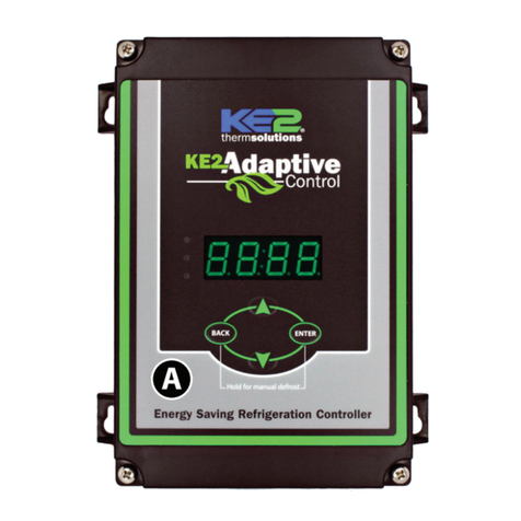
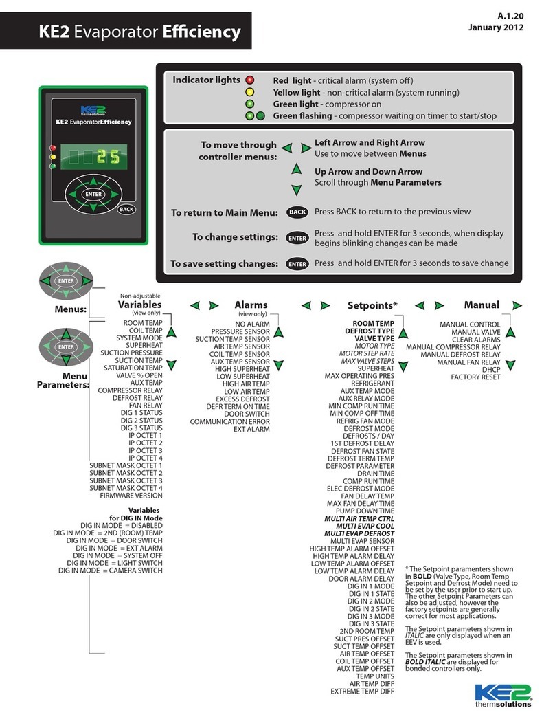
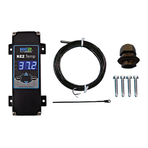
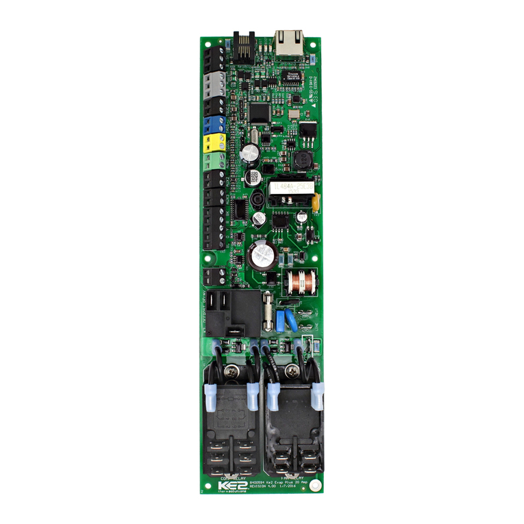
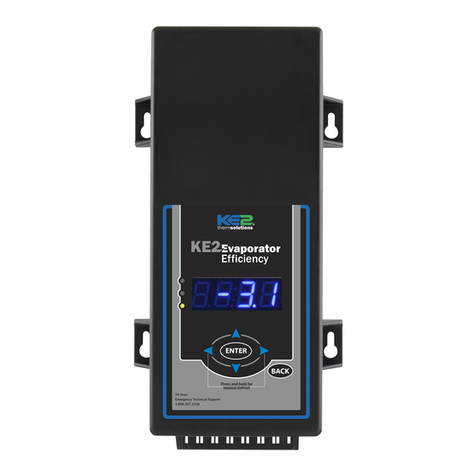
KE2 Efficiency User manual

Parts List
The following parts are included in the
KE2 Evaporator Eciency (KE2 Evap) controller kits:
Kit #20178 with 120/208-240 VAC controller
Kit #20844with 120/208-240 VAC controller
Kit #20631with 120/208-240 VAC controller
Kit #21096with 120/208-240 VAC controller
Kit #20222Beacon® I & II replacement controller
(1) KE2 Evaporator Eciency controller
(1) high voltage safety shield
(3) 10’ temperature sensors
(4) 90 degree quick disconnects
(5) self-tapping screws
(2) course thread screws (1) ne thread machine screw with
lock washer
(1) KE2 Terminal Board
(1) KE2 Evap Navigation sticker
(2) 1/2” plastic knockout plugs
(4) wire ties (rated for low temp)
(1) Air sensor mount
(1) 5-position screw down terminal (for EEV)
(4) 3-position screw down terminals (for power in, transducer
and 3A relay)
(9) 2-position screw down terminals (for sensors and digital
input, analog output)
1) 120 Voltage jumper
(1) 208-240V Voltage jumper (already on back of KE2 Evap)
© Copyright 2015 KE2 Therm Solutions, Inc., Washington, Missouri 63090
Q.1.3
July 2015
KE2 EvaporatorEfciency
Quick Start Guide
Supplies List
The KE2 Evap is supplied with all of the accessories required for the con-
troller to work, however, standard truck stock items will also be required
to install the controller. To simplify the installation, a list of items has
been provided.
Conduit to go between the controller and the evaporator
(2) Conduit connectors (straight or elbow as required)
(11) High voltage wires matched to the load of the heaters, fans,
liquid line solenoid, alarm (if used), and the controller.
(8) Spade Connectors matched to gauge of high voltage wires
Wire labeling (numbers, colors, etc.)
Additional wire ties
18 gauge twisted shielded pair (if extending sensor wires)
Foam insulation if running wires outside the space.
Silicone (for sealing any box penetrations)
Accessories to Aid in Installation
The following parts are available separately:
10’Wire Harness pn 20736,
25’Wire Harness pn 20670
40’Wire Harness pn 20737
KE2 Evap Mounting Box pn 20687
Further information on the Wire Harness and Mounting Box can be found in
literature Q-1-21.
L M N
DE
OP
F
B
Left Arrow & Right Arrow
Use to move between Menus columns
Up Arrow & Down Arrow
Scroll through Menu Parameters
ENTER
Press and hold ENTER for 3 seconds, when
display is blinking changes can be made.
BACK
Press BACK to return to the previous view.
Press and hold ENTER for 3 seconds.
Change settings:
Save changes:
Moving through controller menus:
Return to Main Menu:
Lights: Red - critical alarm (system not running)
Yellow- non-critical alarm (system running)
Green - compressor should be on
- compressor waiting on timer to start/stop
ENTER
Press ENTER to go from parameter to value.
Togglebeween
description & value :
Menu Layout:
Variables Manual*
(view only)
Alarms
(view only)
ENTER
Setpoints Enter
Password
NO ALARM
EMAIL FAILURE
ROOMTEMP
DERIVATIVE
ROOMTEMP
FIRMWAREVERSION
MANUALCONTROL
CLEAR MD
Controller Navigation
ENTER
ENTER
BACK
Press BACK 3 - 4 times
If you lose your place:
*For manual defrost use MANUAL CONTROL
BACK
24-hour Emergency Support: 1.888.337.3358 www.ke2therm.com
pn 21061 9-14
AC
G H
IJ
K
This reference should remain on site with the installed KE2 Evaporator Eciency controller.
A
C
D
E
F
G
H
I
J
K
L
M
N
B
O
P
20844 KE2 Ultimate Install kit includes KE2 Mounting Box pn 20687 and 40’
colored temperature sensors
20631 kit does not include temperature sensors
21096 KE2 Supermarket Retrot kit also includes KE2 Mounting Box pn 20687,
10’ Wire Harness pn 20736, Ethernet Adaptor pn 20938, & Door Switch 20543
20222 Beacon® kit includes an extra temperature sensor, and pressure
transducer with cable.
Now with
Smart Access!
Get your controller
online in 3 easy steps.
See page16

© Copyright 2015 KE2 Therm Solutions, Inc., Washington, Missouri 63090
Q.1.3 July 2015
Page 2
KE2 EvaporatorEfciency
Quick Start Guide
for low temperature applications and 8-10 degrees for medium
temperature.
Subcooling - There should be a solid column of liquid at the inlet of
the valve. This can be veried by looking at the sight glass, however,
the proper method requires measuring the subcooling of the liquid
entering the valve.
Verify Temperature Dierence
A typical Temperature Dierence (TD) between the coil temperature
and the air temperature is between 5 and 15°F. An insucient TD,
between the coil and air temperature, indicates a system issue that
needs to be addressed before installing the KE2 Evap Eciency.
Understanding Frost
The air exiting side of the evaporator is often the coldest spot on the
coil due to the load eecting the temperature. As air travels through
the ns of the evaporator, the Relative Humidity will reach 100%.
Moisture will begin to drop out of the air and deposit on the coil
surfaces to form frost. Although frost typically has a negative con-
notation when discussed in refrigeration, initial frost formation has
a positive eect. Some may even say “frost is our friend.” It is not un-
common to see a small amount of frost on the coils that have KE2
Evaporator Eciency (KE2 Evap) controllers installed. The KE2 Evap
is continually measuring, monitoring, and managing the frost to as-
sist in maximum energy eciency. When the eciency of the coil is
reduced due to excessive frost, the KE2 Evap will initiate a defrost.
Liquid/Vapor Mix
Restrictor,
TEV or EEV
Warm Liquid
Cold Vapor
Hot Vapor
Warm Air
Cold Air
Evaporator
Compressor
Condenser
Saturation Temp °F
(from receiver pressure)
Liquid Temp at Valve °F
Subcooling °
Suction Pressure PSI
Suction Temp °F
(evaporator outlet)
Saturation Temp °F
(calculated from Suct. Pressure)
Superheat °
Temp Dierence (TD) °F
(return air minus coil temp)
Coldest point in evap °F
AMPS
Trouble Shooting Diagram
Discharge Pressure PSI
Refrigerant
Arriving at the Jobsite
When arriving at any jobsite, it is good practice to verify the correct
operation of the system. Even systems running for a considerable
amount of time without requiring a service call may not be running
properly.
Inspect the coil to see the current frost pattern. If the unit has not
recently performed a defrost, look for the heaviest area of frost. This
will be used to locate the coil sensor.
Installers should account for a full system diagnostic in the installa-
tion estimate for the controller.
Although it may seem unnecessary, identifying system issues before
the controller is installed will save time overall. It will also allow the
controller to provide the highest energy savings.
Verify the system is running correctly. Taking several measurements
will help determine the current health of the system. Using the dia-
gram below, ll in the necessary information.
Two of the most critical indicators of system health are the super-
heat and subcooling.
Superheat - Superheat is the most overlooked ineciency in exist-
ing systems. Typically the superheat on a TEV is set when there is not
product in the controlled space, if it is set at all.
When applying the controller to an existing system with a mechani-
cal expansion valve, the superheat should be between 6-8 degrees

Q.1.3 July 2015
Page 3
© Copyright 2015 KE2 Therm Solutions, Inc., Washington, Missouri 63090
KE2 EvaporatorEfciency
Quick Start Guide
A
IMPORTANT Preliminary Steps
Determine the coil sensor location
To determine the most appropriate sensor location, when arriving on
site, put the system into defrost.
The location where frost is last to disappear is where the coil sensor
should be placed. Monitor both the air entering side, as well as the air
exiting side, of the evaporator coil. Don’t be surprised if the last place
for frost to disappear is on the air exiting side. It is usually near the
right or left end of the coil.
It is important to verify all heating elements are working properly.
B
C
Steps to Ensure Proper Coil Sensor Location
More often than not on coils, the location of the sensor is a short
distance from the end, approximately 1 to 1-1/2”away from the right
and left edges of the active coil surface. The ice tends to grow from
these edges towards the center. Therefore, the sensor location is best
situated approximately 1 to 1-1/2”from the outer edges and typically
near the bottom 1/3rd portion of the evaporator. The sensor needs to
be as far away from the defrost heat sources as possible.
This is most easily located by viewing the current frost pattern. The
last place frost disappears during the defrost cycle is the correct sen-
sor location.
Note: Insert plug (Item I from parts list) into coil housing when
mounting sensor wire to prevent damage to the sensor from
sharp edges. Two plugs are provided. One plug should be inserted
into the inner housing to access the coil, and the other into the outer
housing to exit the coil. Installer must puncture plug to insert sensor.
As with any wiring installation, it is appropriate to leave a service
loop. Enough wire should be left to move the sensor to the opposite
end of the evaporator.
DMake note of the locations you have determined for placement
of the coil sensors.
Typically last spots to defrost
B
Locate sensor approx.
1-1/2” from end, in the
bottom third of coil
Item I from Parts List on page 1
C

© Copyright 2015 KE2 Therm Solutions, Inc., Washington, Missouri 63090
Q.1.3 July 2015
Page 4
KE2 EvaporatorEfciency
Quick Start Guide
KE2EvaporatorEfficiency
TM
thermsolutions
ENTER
BACK
2
2
KE2EvaporatorEfficiency
TM
thermsolutions
ENTER
BACK
2
2
KE2EvaporatorEfficiency
TM
thermsolutions
ENTER
BACK
2
2
At the entrance
On the wall
On the evaporator
11 Determining Location
The controller is designed to be as versatile as possible. The loca-
tion should be discussed with the end users to determine if they have
a preference. It is designed so it can be installed inside or outside the
controlled space.
The controller can also be located at the condenser, but should not
be installed outdoors without an enclosure to protect it from sun-
light and moisture (must be within operating range -40°F to 140°F)
KE2 EvaporatorEfficiency
TM
thermsolutions
ENTER
BACK
2
2
Evaporator
?
Cut a length of conduit to go from the controller to the evaporator
Measure the distance between the controller and evaporator to ac-
count for the extra length necessary to properly route conduit.
Determine the number of wires to go to the controller.
Controller power (3 wires)
Fan control (2 wires)
Defrost (heater) control (2 wires)
Liquid line solenoid (2 wires)
If the Aux Relay is used, the installer will need to supply an ad-
ditional pair of wires to the controller
Aux relay (2 wires)
Note: Install in accordance with local wiring codes. KE2 Therm
does not accept responsibility for incorrect or unsafe wiring.
2
2
Cut wires to length
Once the number of wires is determined, cut the wires to length.
The wire should be long enough to account for the necessary con-
nections in the controller and evaporator.
Use the optional KE2 Wire Harness, or select dierent colored wires,
(blue - fan, orange - heaters, yellow - solenoid, purple - alarm). This
will simplify the installation and troubleshooting. If only a single
color is available, both ends of the wires should be labeled with a
matching number. This will save time when wiring the evaporator.
33
Determine the current draw of the unit.
Using the nameplate to determine the Amp rating of the unit. This
information should be used to select the proper sized wire. It should
also be used to verify the unit does not exceed the relay rating on the
KE2 Evaporator Eciency controller.
4
4

Q.1.3 July 2015
Page 5
KE2 EvaporatorEfciency
Quick Start Guide
© Copyright 2015 KE2 Therm Solutions, Inc., Washington, Missouri 63090
Preparing conduit
Feed the wires through the conduit.
The conduit connectors can be added at this time. Determine if a
straight or 90 degree connector is most appropriate for the installa-
tion, and attach to the conduit.
Securely connect one end of the conduit to the controller.
5 5
120V 208-240V
6
Controller Power
Strip the end of the wires used to provide power to the controller (If
using the KE2 Wire Harness the wires are pre-stripped)
Locate a 3 position terminal in the accessories kit.
Fasten to the 3 position pluggable connector*.
Plug into the board as indicated in Wiring Schematic.
*All terminal screws should be tightened to 5 ft-lbs.
7
7
Wiring the controller
Locate the second Voltage Jumper in the accessory kit.
It is a 4 position plug with 2 red jumper already installed.
Use the plug with 1 jumper for 208-240V power or the jumper with
2 jumpers for 120V power.
Power is not connected to Voltage selector, it is a selector only.
Power for the controller is connected to the Power In location us-
ing a 3 position connector.
Controller still illuminates display when 120V is applied with 208-
240V selected, however controller will not function properly.
6
Fan Relay
Strip the end of the 2 wires used for fan control.
Locate 2 female spade connectors in the accessories kit.
Crimp on the female spade connectors.
Plug the connectors to the COM and NO positions of the Fan Relay.
Fan Relay Using the KE2 Wire Harness
The blue wires are used for fan control.
They are blue with a black stripe, and the black with a blue stripe.
Plug the black with a blue stripe to the COM terminal.
Plug the blue with a black stripe to the NO position of the Fan Relay
Conrm combined fan motor load is not over 10 amps
88
Defrost (Heater) Relay
Strip the end of the 2 wires used for the defrost control.
Locate the remaining 2 female spade connectors in accessories kit.
Crimp on the female connectors.
Plug the connectors to COM and NO positions of the Defrost Relay.
Defrost (Heater) Relay Using the KE2 Wire Harness
The orange wires are used for the heater control.
Locate the orange with black stripe, and black with orange stripe.
Plug the black with orange stripe to the COM terminal.
Plug the orange w. black stripe to the NO position of Defrost Relay.
Conrm combined heater load is not over 20 amps.
99

Q.1.3 July 2015
Page 6
KE2 EvaporatorEfciency
Quick Start Guide
© Copyright 2015 KE2 Therm Solutions, Inc., Washington, Missouri 63090
Liquid Line Solenoid /Compressor Relay
the liquid line solenoid pluggable connector is supplied with an
in-line fuse to protect the controllers circuitry.
Locate a 3-position connector from the accessories kit.
Fasten the incoming power to the fused lead and the lead from the
liquid line solenoid to the NO terminal position.
Plug into the location as indicated in Wiring Schematic.
Liquid Line Solenoid (LLS)/Comp. Relay Using KE2 Wire Harness
The yellow wires are used for Liquid Line Solenoid control.
Locate a 3-position connector from the accessories kit.
Fasten the black with yellow stripe to the fused lead.
Fasten yellow w. black stripe from the LLS to NO terminal position.
Plug into the location as indicated in Wiring Schematic.
Max relay rating is 3A.
10 10
Auxiliary Relay
If using the Auxiliary Relay, the installer will need to supply an ad-
ditional pair of wires to the controller.
Strip approx. 1/4”wire insulation on end of the 2 wires for the alarm
Locate a 3-position connector from the accessories kit.
Plug into the location as indicated in Wiring Schematic.
Max relay rating is 3A.
11
11
Preparing the Evaporator
The evaporator wiring will require access to the high voltage termi-
nal block on the coil.
Turn o power to the system.
Verify power is no longer present using a multimeter.
Note: Before installing the safety cover, plug in any remaining connec-
tors to store for future use.
Install Safety cover
Once all of the high voltage wiring is complete, install the metal
cover on the controller.
Locate the cover and 3 small screws from the accessories kit.
Position the cover over the 3 mounting posts.
Using 2 course thread screws attach controller to the plastic posts.
Use the ne threaded machine screw with lock washer to fasten the
controller to the metal post.
Set the controller in a safe place.
12 12
13 13
14
Evaporator wiring
Now that the conduit is prepared, it can be connected to the
evaporator.
Locate the proper sized knockout and carefully remove knockout.
Connect conduit to the evaporator
14

Q.1.3 July 2015
Page 7
KE2 EvaporatorEfciency
Quick Start Guide
© Copyright 2015 KE2 Therm Solutions, Inc., Washington, Missouri 63090
Study the existing wiring.
Determine the location of the fol-
lowing: incoming power, fan leads,
heater leads, defrost termination
leads, and fan delay leads.
15
Evaporator wiring – Controller
Strip the end of the wires used to
power the controller.
Attach to the line power to provide
continuous power to the controller.
Attach ground wire.
Note: Ground is required for the inter-
nal safeties to operate properly.
16
Evaporator wiring – Fans
Strip the ends of the wires (con-
nected to the KE2 Evap) used to con-
trol the evaporator fans.
The fan wires can be attached
to the terminal block using either
screw down terminals or spade
connectors.
Attach one of wires to the L1/Line.
This wire will be connected to COM
of fan relay on the controller.
Attach the wire connected to the
NO terminal on the Fan Relay to one
of the fan leads.
Connect L2/Neutral to remaining
fan lead.
17 17
16
KE2 Terminal Board
KE2 Terminal Board

Q.1.3 July 2015
Page 8
KE2 EvaporatorEfciency
Quick Start Guide
© Copyright 2015 KE2 Therm Solutions, Inc., Washington, Missouri 63090
Evaporator wiring – Heater
Strip the ends of the wires being
used for heater control.
The heater wires can be attached to
the terminal block using either screw
down terminals or spade connectors.
18
Evaporator wiring – Liquid Line
Solenoid /Compressor
Strip the ends selected to control
the liquid line solenoid.
Attach the wire from the NO termi-
nal on the L.L. Solenoid/Compressor
relay to one of the solenoid leads.
Attach the wire from the COM on the
L.L. Solenoid/Compressor relay to the
L1/Line Voltage.
Connect L2/Neutral to the remain-
ing L.L. Solenoid/Compressor lead.
20
Remove defrost termination
(Klixon®) from circuitry
Attach one of wires to the L1/Line.
This wire will be connected to COM of
defrost relay on the controller.
Attach the wire connected to the
NO terminal on the Defrost Relay to
one of the defrost leads.
Connect L2/Neutral to the remain-
ing defrost lead.
The defrost safety should not be re-
moved from the circuit. Its purpose is
to prevent the heaters from over heat-
ing and causing damage.
19
18
20
KE2 Terminal Board
KE2 Terminal Board

Q.1.3 July 2015
Page 9
KE2 EvaporatorEfciency
Quick Start Guide
© Copyright 2015 KE2 Therm Solutions, Inc., Washington, Missouri 63090
Wiring Schematic - Controller New Installation

Q.1.3 July 2015
Page 10
KE2 EvaporatorEfciency
Quick Start Guide
© Copyright 2015 KE2 Therm Solutions, Inc., Washington, Missouri 63090
Evaporator Fan Motors
Con1 Max HP & Amp Ratings (Total All Fans)
Voltage Max HP Max AMPS
230 3Ø 15 42
460 3Ø 30 40
575 3Ø 30 32
Wiring Schematic - Controller with KE2 Contactor Box
Existing Defrost Heaters Max Current Ratings
(Amps are Total All Heaters)
Relay Box P/N 230V 3Ø460V 3Ø575V 3Ø
20217 54 Amps 52 Amps 52 Amps
20218 68 Amps 65 Amps 62 Amps
20219 80 Amps 77 Amps 62 Amps
Legend
EFM - Evaporator Fan Motor
DH - Defrost Header
LLS - Liquid Line Solenoid
AUX - Auxiliary
PT - Pressure Transducer
T1 SUCTION - Suction Temperature
T2 AIR - Return Air Temperature
T3 COIL - Evaporator Coil Temperature
T4 AUX - Auxiliary Temperature
EEV - Electric Expansion Valve
ECM - Electronically Commutated Motor
D1 - Digital Input 1
D2 - Digital Input 2
D3 - Digital Input 3
- - - By others
All eld wiring must conform to
local codes
Contactor ratings per UL508 CSA 22.2
Wiring Schematic - Controller with KE2 Contactor Box
P/N: 20217 - 50A
20218 - 65A
20219 - 80A

© Copyright 2015 KE2 Therm Solutions, Inc., Washington, Missouri 63090
Q.1.3 July 2015
Page 11
KE2 EvaporatorEfciency
Quick Start Guide
Evaporator wiring – Auxiliary
The auxiliary relay is optional and wiring will vary depending on the
auxiliary relay method selected.
Depending on auxiliary relay location, an additional conduit may
be required.
Strip the ends selected to control the auxiliary component.
Break the hot leg of the auxiliary component.
Attach the wire from the NO terminal on the auxiliary relay to one
of the auxiliary component leads. Attach the wire from the COM on
the auxiliary component relay to the L1/Line Voltage.
Connect L2/Neutral to the remaining auxiliary component lead.
Route and secure the conduit to the location the controller is to be
installed.
Wiring must follow local wiring codes.
22 22
Installing the sensors
Although not required, sensors should be labeled with their func-
tion. This will eliminate confusion when connecting the sensors to
the controller.
Air Sensor Bracket
Install the Air Temperature Sensor using the Stainless Steel self-
piercing screw and bracket from the accessory kit.
The end with the single loop is designed to be mounted with the
screw included.
The end with multiple loops is designed to hold the sensor.
Locate the best place to install the sensor.
The sensor should be located between 8 - 10 inches away from
the face of the evaporator. This distance prevents the sensor from
sensing heat from the heating elements during the defrost cycle, but
close enough to accurately sense the return air temperature.
The sensor bracket may be bent as necessary to locate the sensor
in the proper position.
WARNING!
Do not allow the metal portion of the air sensor to touch any-
thing other than air. It should not touch the bracket, nylon cable
tie, or any other solid surface.
23
23
21
Coil Sensor
The coil sensor location is of the utmost importance for the
proper operation of the controller. It is essential that the sen-
sor is in the coldest location on the coil at the end of the defrost
cycle, to ensure a complete defrost. See preliminary steps A-D on
page 3 to determine the coldest location on the coil.
Once you determine the proper sensor location, as described in pre-
liminary steps A-D on page 3, the sensor can be installed.
1.5”
Thermistor
Epoxy
.5”
24
Installing the Sensor Properly
Note, the most active portion of the sensor is the rst 1/2” of the
1-1/2” long stainless steel probe. Figures 25 and 26 show two meth-
ods for installing the sensor in the coil. The method shown in 25 will
work in most applications, however in some cases inserting the sen-
sor into the coil may position it too close to the defrost heat source. In
these instances, the method shown in Figure 26 can be used.
24

A B
KE2 EvaporatorEfciency
Quick Start Guide
Q.1.3 July 2015
Page 12
© Copyright 2015 KE2 Therm Solutions, Inc., Washington, Missouri 63090
Alternate method - As the defrost termination sensor, it is important
to ensure the sensor does not terminate defrost before all frost has
been removed from the coil. In some installations, inserting the sen-
sor into the coil may position it too close to the defrost heat source.
An alternate method of positioning places the sensor vertically be-
tween the coil ns. This shows the coil sensor properly secured.
Extending sensor wires
After the sensors are mounted, they are routed back to the control-
ler. If the wires must be extended, use 18 gauge twisted shielded
pair. Maximum length for 18 gauge: 100ft.
When running the wires back to the controller care must be tak-
en to avoid interference being introduced into the sensor wires.
Interference can be introduced when sensor wires are located
near high voltage lines. High voltage is dened by Underwriter’s
Laboratories as above 30V. The higher voltage the more likely it is to
introduce interference, and the more important to avoid.
If crossing a high voltage line is necessary, the sensor wiring should
be run at right angles to prevent noise.
25
Figure 25A shows the sensor touching two circuit tubes. When in-
serting the sensor into the coil, the tip should touch one of the cir-
cuit tubes. It should not be located adjacent to the electric heating
elements. It should be about half the distance between the heat-
ers if possible. In Figure 25B the probe is inserted into the ns ap-
proximately 1/16” deeper than the stainless shielding. Pinch the ns
gently together, securing the sensor in place. This provides thermal
ballast to ensure a complete defrost.
25
26
Connecting sensor wires to controller
The temperature sensors are designed to be attached to the con-
troller using 2 position screw terminals. Using a connector from the
accessory kit, attach the sensor to the screw terminal. The sensors are
not polarized, so wire location does not eect sensor performance.
Connect all sensors to a screw terminal.
Once connected, the sensors should be plugged into the proper lo-
cation on the controller. The location can be determined from the la-
bel on the interior wall of the enclosure or from the Wiring Schematic.
Strain relief
The enclosure is designed with a strain relief bar to prevent the sen-
sor wires from becoming unplugged from inadvertent contact.
Before securing the sensor wires, create a service loop. Figure 27.
Using a cable tie from the accessory kit, securely fasten the sensor
wires to the strain relief bar.
Note: Unused connectors should be placed (installed) in their re-
spective location for future use.
27
Controller Mounting
Locate the 4 stainless steel screws in the accessories kit
Install the 4 screws
Place the controller on the mounting screws and tighten down the
screws.
28
28
Final Step
Leave the installation instructions onsite in a convenient location,
where it can be easily located, for future service.
29
26
27

© Copyright 2015 KE2 Therm Solutions, Inc., Washington, Missouri 63090
Q.1.3 July 2015
Page 13
KE2 EvaporatorEfciency
Quick Start Guide
Specications
Controller
Input Voltage: 120V or 208 - 240V
Ambient Temp: -40° to 140°F
Operating Temp: -40° to 140°F
Display: 4-digit alphanumeric LED
IP Rating: IP65
Inputs: (4) temperature sensors (KE2 SKU 20200)
(1) pressure transducer (KE2 SKU 20204)
Valve Types: unipolar and bipolar stepper motors (12V) (Beacon®is 21V)
Relays:
20A resistive (defrost)
10A inductive (evaporator fan)
(2) 3A inductive rated cycles
Digital Input 1: door contact, use 2nd air temp setpoint, disabled, system
o, external alarm notication
Digital Input 2: door contact, use 2nd air temp setpoint, disabled, system
o, external alarm notication, defrost lockout, defrost
interlock
Digital Input 3: door contact, use 2nd air temp setpoint, disabled, system
o, external alarm notication, lights
Communication: Standard TCP/IP
Pressure Transducer - pn 20201 (10 ft lead) or pn 20204 (40 ft lead)
Pressure Range: 0 to 150 psia
Proof Pressure: 450 psi
Burst Pressure: 1500 psi
Operating Temp: -40° to 275°F
Temperature Sensor
Sensor Specs: -60° to 150°F moisture resistant package
208-240
120
120
Temperature Sensors Pressure
Transducer
T1SuctT4Aux T2AirT3Coil
line /L1
ground
neutral /L2
NC
NO
NO NC
NO NC
COM
COM
NC
Power In
green
red
black
NO
Transformer
3A Relay
3A Relay
COM
COM
COM NC
NO
COM NC
NO
18V
DI 1
DI 3
DI 2
Electric Valve:
Temperature Sensors (4) Pressure Transducer
RJ45 Ethernet Connection
DAC for ECM Fan
Fuse
empty
red
green
white
black
Auxiliary Relay
Fan Relay
(10 amp)
ground
signal +5
Defrost (Heater) Relay
(20 amp)
1/2 or 500mA
Time Delay
Liquid Line Solenoid
Power In
(compressor)
door switch
system o
dual temp setting
external alarm
light switch
defrost interlock
defrost lockout
Digital Inputs
Pressure Transducer
Wiring Detail
black
red
green
Voltage
Selector
120V - Jumpers
1&2 3&4
208-240V Jumper
2&3 only
1 2 3 4
0-10V analog out
+
_
KE2 HSV KE2 RSV
blue
orange
yellow
red
black
yellow
blue
red
white
black
Beacon® I
blue
red
white
black
Beacon® II
brown
green
white
black
Beacon® II
Part Number
20222 Beacon
replacement
controller
required.
Wiring Diagram

KE2 EvaporatorEfciency
Quick Start Guide
Q.1.3 July 2015
Page 14
© Copyright 2015 KE2 Therm Solutions, Inc., Washington, Missouri 63090
Table 1 - Controller Navigation - Menu Structure
Menu
Parameters:
MANUAL CONTROL
MANUAL VALVE4
CLEAR ALARMS
MANUAL COMPRESSOR RELAY
MANUAL DEFROST RELAY
MANUAL FAN RELAY
MANUAL AUX RELAY
FACTORY RESET
WEB PASSWORD RESET
SMART ACCESS
DHCP
DOD INIT
CLEAR MD
Menus: Variables Manual
(view only)
Non-adjustable
NO ALARM
PRESSURE SENSOR
SUCTION TEMP SENSOR
AIR TEMP SENSOR
COIL TEMP SENSOR
AUX TEMP SENSOR
HIGH SUPERHEAT
LOW SUPERHEAT
HIGH AIR TEMP
LOW AIR TEMP
EXCESS DEFROST
DEFR TERM ON TIME
DOOR SWITCH
COMMUNICATION ERROR
EXT ALARM
EMAIL FAILURE
FTP
SNTP
Alarms
(view only)
ENTER
ENTER
Left and Right Arrows Use to move between Menus
Up Arrow and Down Arrow
Scroll through Menu Parameters
ENTER
Press and hold ENTER for 3 seconds, when display
begins blinking changes can be made
BACK
Press BACK to return to the previous view.
ENTER
Press and hold ENTER for 3 seconds to save change
To change settings:
To save setting changes:
To move through
controller menus:
To return to Main Menu:
Indicator lights Red light - critical alarm (system o)
Yellow light - non-critical alarm (system running)
Green light - compressor on
Green ashing - compressor waiting on timer to start/stop
KE2 EvaporatorEfficiency
TM
thermsolutions
ENTER
BACK
2
2
1 T1 and T4 are parameters that
can be set to various functions.
The default for T1 is Suction
Temp, the T4 is Coil Temp.
2 The Setpoint paramenters
shown in BOLD (Valve Type,
Room Temp Setpoint and
Defrost Mode) need to be set by
the user prior to start up. The
other Setpoint Parameters can
also be adjusted, however the
factory setpoints are generally
correct for most applications.
3 The Setpoint parameters shown
in ITALIC are only displayed
when a Custom EEV is used.
4 Displayed when an EEV is used.
5 Only available if mechanical
valve is selected. When using an
electric valve the default,
suction temperature, is required.
6 The Setpoint parameters shown
in BOLD ITALIC are used for
bonded controllers only.
7 Only displayed when Run Time
Defrost is selected.
ROOM TEMP
COIL TEMP
SYSTEM MODE
SUPERHEAT
SUCTION PRESSURE
T1 SUCTION TEMP1
SATURATION TEMP
VALVE % OPEN4
T4 AUX TEMP1
COMPRESSOR RELAY
DEFROST RELAY
FAN RELAY
AUX RELAY
DIG 1 STATUS
DIG 2 STATUS
DIG 3 STATUS
IP OCTET 1
IP OCTET 2
IP OCTET 3
IP OCTET 4
SUBNET MASK OCTET 1
SUBNET MASK OCTET 2
SUBNET MASK OCTET 3
SUBNET MASK OCTET 4
FIRMWARE VERSION
ENTER
Press ENTER to go from parameter to value.
To toggle beween
description and value :
ROOM TEMP2
DEFROST TYPE2
VALVE TYPE2
MOTOR TYPE3
MOTOR STEP RATE3
MAX VALVE STEPS3
SUPERHEAT4
MAX OPERATING PRES4
REFRIGERANT
AUX TEMP 4 MODE
AUX TEMP 1 MODE5
AUX RELAY MODE
FAN SPEED
MIN COMP RUN TIME
MIN COMP OFF TIME
REFRIG FAN MODE
DEFROST MODE
DEFROSTS / DAY
1ST DEFROST DELAY
DEFROST FAN STATE
DEFROST TERM TEMP
DEFROST PARAMETER/MAX DEFROST TIME
DRAIN TIME
COMP RUN TIME7
ELEC DEFROST MODE
FAN DELAY TEMP
MAX FAN DELAY TIME
PUMP DOWN TIME
MULTI AIR TEMP CTRL
MULTI EVAP COOL6
MULTI EVAP DEFROST 6
MULTI EVAP SENSOR6
HIGH TEMP ALARM OFFSET
HIGH TEMP ALARM DELAY
LOW TEMP ALARM OFFSET
LOW TEMP ALARM DELAY
DOOR ALARM DELAY
DIG IN 1 MODE
DIG IN 1 STATE
DIG IN 2 MODE
DIG IN 2 STATE
DIG IN 3 MODE
DIG IN 3 STATE
2ND ROOM TEMP
SUCT PRES OFFSET
SUCT TEMP OFFSET
AIR TEMP OFFSET
COIL TEMP OFFSET
AUX TEMP OFFSET
TEMP UNITS
AIR TEMP DIFF
EXTREME TEMP DIFF
PROPORTIONAL
INTEGRAL
DERIVATIVE
Setpoints
Variables for DIG IN STATUS
DISABLED
2ND (ROOM) TEMP
DOOR SWITCH
EXT ALARM
SYSTEM OFF
DEFROST LOCKOUT
DEFROST INTERLOCK
Enter
Password

Q.1.3 July 2015
Page 15
© Copyright 2015 KE2 Therm Solutions, Inc., Washington, Missouri 63090
KE2 EvaporatorEfciency
Quick Start Guide
Table 1 shows the menu structure of the controller. The default dis-
play of the controller always displays the actual room temperature.
Pressing the ENTER button will display room temp ROOM TEMP.
Pressing the up and down arrows moves the display through the
VARIABLES menu. See Controller Navigation on page 16. By de-
fault, the controller only allows access to the room temperature. The
VARIABLES menu consists of the current sensor readings and the
relays’ state. The User Password (1111) only provides access to the
ROOM TEMP setpoint.
For the protection of the system, access to the SETPOINT and
MANUAL control requires an Installer Password (2222). Pressing
the right or left arrow will move from the Variables menu to the next
menu, shown in the Controller Navigation on page 16 a complete list
of parameters is shown in Table 3.
Pressing the BACK key at any time will return the user to next level
up the menu. A second press will either return to the Main Menu or
to the room temperature reading.
Table 2 - Introduction Mode
Mechanical Valve
TEV - 4 steps
Dened EEV
5 steps
Custom EEV
8 steps
Room Temp Room Temp Room Temp
Defrost Type Defrost Type Defrost Type
Valve Type Valve Type Valve Type
Smart Access Refrigerant Refrigerant
Smart Access Motor Type (Unipolar/Bipolar)
Motor Step Rate
Max Valve Steps
Smart Access
Web Login
When accesssing the controller using the webpage, the Username
and Password are required.
The defaults are set as: User: ke2admin Password: ke2admin
IMPORTANT: The Password should be changed from the default
for security purposes.
User Interface
The KE2 Evap’s onboard user interface uses a familiar 6-button ar-
rangement to simplify navigation through the controller’s menus.
The menu has been grouped by category to provide an easy to pro-
gram structure. By grouping the menu by each functional area, the
user is not required to scroll though unrelated setpoints to access the
desired functionality.
The left and right arrows move between the categories. When
pressed while in a menu, the left and right arrows will move to the
main screen or the adjacent menu.
The up and down arrows move the user through the available op-
tions for each group. All users are allowed access to the variable
alarms. All other information is password protected to prevent unau-
thorized access to the controller’s functionality.
The ENTER button is used to save an input option when it has been
changed. The enter button must be held for 3 seconds to prevent
accidental changes. Changes may be discarded by waiting, to allow
the controller to timeout and return to default screen, or hitting the
BACK button.
The BACK button is used to return to the previous screen. Pressing
the BACK button twice at any time will return the user to the default
view. See Table 1.
Controller Setup
Upon initially applying power to the controller, the controller will ini-
tialize, then automatically enter the Introduction Mode. The Intro-
duction Mode consists of as little as 3 setpoints that must be cong-
ured for KE2 Evap to begin controlling the system. See Table 2.
The rst setpoint the user is asked to enter is the desired ROOM
TEMP. This is followed by the DEFROST TYPE. The controller is de-
signed to work with electric, hot gas, and o time defrosts. The last
setpoint is the VALVE TYPE. The controller is defaulted to be used
with a mechanical valve, but may be used with a variety of EEVs, in-
cluding a customer dened valve. To easily view your controller on-
line enable SMART ACCESS.
These are the only setpoints required to begin controlling the sys-
tem, when applied on a single evaporator with a mechanical valve.
If using a standard/predened EEV, the user will also be prompted to
specify the REFRIGERANT. The KE2 Evap may also be applied to user
dened EEVs. When this option is selected, the user will be prompted
to select MOTOR TYPE, MOTOR STEP RATE, and MAX VALVE STEPS.
Once these have been set, the KE2 Evap will begin controlling EEV
and the system.
Adjusting Controller Parameters
The controller has the ability to access an abundance of informa-
tion from the 4-digit alphanumeric display. However, the controller
requires a password, adding a degree of protection from unwanted
modications. The controller will prompt the user for a password
PASSWORD when the user attempts to access setpoints they do not
have permission to change.

© Copyright 2015 KE2 Therm Solutions, Inc., Washington, Missouri 63090
Q.1.3 July 2015
Page 16
KE2 EvaporatorEfciency
Quick Start Guide
Introduction to Smart Access
Smart Access provides quick and easy, real time access to your refrig-
eration systems 24/7
The KE2 Evap controller has always been internet accessible, but
now it is easier than ever to monitor and adjust your KE2 Evap
remotely. With the new version 4.0 firmware Smart Access is in-
cluded.
Smart Access doesn’t require port forwarding or establishing a
vpn. All the KE2 Evap needs is a physical connection to the net-
work router with a cat 5 cable. Smart Access will automatically
connect to your personal web portal.
And, Smart Access provides a “customized” dashboard of all the
controllers on that network on one page.
Preliminary
Connect the KE2 Evap to the customer’s network.
CAT5 Ethernet
Cable
KE2 EvaporatorEfficiency
TM
thermsolutions
ENTER
BACK
2
2
1 2 3 654 7
Link/ACT
100/1000Mbps
POWER
Customer Network
Screen shot of a single KE2 Evap connected through Smart Access
Screen shots of Smart Access dashboard. Controller and system information is displayed for all of the
controllers on the portal.
Benets of Smart Access
Smart Access auto launches, and can eliminate
the need for costly IT support
Doesn’t require port forwarding or a vpn
Customized dashboard lets you remotely view
all the controllers on one page
It’s easier than ever to set up every controller
you service to provide alarm notications via
text or e-mail
Easy setup of remote monitoring & system
control

Smart Phone
MODIFY STATUS
ABC Contracting
(888)555-3358
All Clear
Compressor
On
System Mode
Cool Evaporator Fan
Off
Room Temp
-8.5 F Coil Temp
15.4 F
Sat Temp
46.0 F
Superheat
0.0 F Valve Position
Manual
Suct Pressure
96.2 F Suct Temp
87.7 F
Dig Input 3
Dis
Defrost
Off Aux Temp
Dis
Dig Input 1
Closed Dig Input 2
Dis
PC/Mac iPad/Tablet
MODIFY STATUS
ABC Contracting
(888)555-3358
All Clear
Compressor
On
System Mode
Cool Evaporator Fan
Off
Room Temp
-8.5 F Coil Temp
15.4 F
Sat Temp
46.0 F
Superheat
0.0 F Valve Position
Manual
Suct Pressure
96.2 F Suct Temp
87.7 F
Dig Input 3
Dis
Defrost
Off Aux Temp
Dis
Dig Input 1
Closed Dig Input 2
Dis
© Copyright 2015 KE2 Therm Solutions, Inc., Washington, Missouri 63090
Q.1.3 July 2015
Page 17
KE2 EvaporatorEfciency
Quick Start Guide
Step 3
Enter default information
Enter default information, and click Log In button.
Site: installer
Password: controllers Mac Address
(from sticker on back of controller)
Step 1
Enable Smart Access in the
Introduction Mode menu
After setting the Room Temp, Defrost Type and
Valve Type, set Smart Access to Enabled.
Use the or arrow to change Smart Access
to Enabled. Press and hold the
ENTER
button for 3
seconds to save the change.
Note: if using a Dened EEV, Refrigerant must be
selected too.
Note: if using a Custom EEV Refrigerant, Motor
Type, Motor Step Rate, and Max Valve Steps must be
selected.
Introduction Mode
Mechanical Valve TEV
4 steps
Dened EEV
5 steps
Custom EEV
8 steps
Room Temp Room Temp Room Temp
Defrost Type Defrost Type Defrost Type
Valve Type Valve Type Valve Type
Smart Access Refrigerant Refrigerant
Smart Access Motor Type (Unipolar/Bipolar)
Motor Step Rate
Max Valve Steps
Smart Access
1
1
1
Step 2
Go to smartaccess.ke2therm.net
Using your PC, tablet or smartphone, enter
http://smartaccess.ke2therm.net in the web
browser’s address bar.
Smart Access - Online Access In 3 Easy Steps
installer
IP-10.10.52.19
MAC
00:04:A3:14:E5:92
IP-10.10.52.19
MAC
00:04:A3:14:E5:92
For additional information on SmartAccess, visit
http://ke2therm.com/productliteratureevap4.
html, and see bulletins A.1.76 The KE2 Evap v4.0
with Smart Access and Q.1.34 Smart Access Setup
and Customizing.

KE2 EvaporatorEfciency
Quick Start Guide
Q.1.3 July 2015
Page 18
Setpoints Menu - STPT
Parameter Name Description Range Default Current
ROOM TEMP Walk-in freezer or cooler room temperature to be maintained -50°F to 90°F -10°F
DEFROST TYPE Method of defrost used on the evaporator coil: Electric, Air, Hot Gas with Liquid Line Solenoid/Compressor relay o, Hot Gas with
Liquid Line Solenoid/compressor relay on ELEC, AIR, HOT GAS COMP ON, HOT GAS COMP OFF ELEC
VALVE TYPE Type of valve used on the system: mechanical, pre-congured electric, custom EEV conguration MECHANICAL, KE2 RSV, KE2 HSV, SER/SEI 1 TO 20, SER B TO L, SEI 30, SEI 50, SEH, ETS12 TO 50,
ETS100, ETS250/400, CAREL, CUSTOM; MECHANICAL
Custom
EEV only
MOTOR TYPE If VALVE TYPE = CUSTOM: The motor type used in the valve BIPOLAR, UNIPOLAR BIPOLAR
MOTOR STEP RATE If VALVE TYPE = CUSTOM: The motor speed setting in number of steps per second 30 to 400 steps/second 200 steps
MAX VALVE STEPS If VALVE TYPE = CUSTOM: The total number of steps required to move the valve from closed to fully open 200 to 6400 steps 1600 steps
SUPERHEAT The superheat value that the controller will maintain, (not applicable if VALVE TYPE = MECHANICAL) 5°F to 30°F 8°F
MAX OPERATING PRES The maximum allowable suction pressure, (not applicable if VALVE TYPE = MECHANICAL) 10-500 psig if R-744 selected, 10-300psig if R-410A selected, 10-150 psig all other refrigerants 150 psig
REFRIGERANT The type of refrigerant used in the refrigeration system 404A, R507, 407A, 407C, 422A, 422D, 134A, R22, R717, 438A, 408A, 409A, 407F, 410A, R744 404A
AUX TEMP 4 MODE Conguration mode of the auxiliary temperature sensor DISABLED, MONITOR, T4 ROOM TEMP, T4 COIL TEMP DISABLED
AUX TEMP 1 MODE Conguration mode of the auxiliary temperature sensor (Not available if EEV is selected) T1 SUCTION TEMP, MONITOR, T1 ROOM TEMP, 2ND COIL TEMP T1 SUCTION
AUX RELAY MODE Conguration mode of the auxiliary relay. ALARM RELAY, 2ND COMP RELAY, 2ND FAN RELAY, 2ND DEFR RELAY, 2 SPEED FAN CTL, LIGHT
RELAY, PERM DEFROST RELAY ALARM RELAY
FAN SPEED Provides 0-10V DC signal to control variable speed -100% to 100% 0.000 (O)
MIN COMP RUN TIME Minimum amount of time the liquid line solenoid/compressor relay must remain on after it is energized 0 to 15 minutes 2 minutes
MIN COMP OFF TIME Minimum amount of time the liquid line solenoid/compressor relay must remain o before it can be energized again. 0 to 15 minutes 5 minutes
REFRIG FAN MODE Fan operation while in refrigeration mode ON WITH COMPRESSOR, PERMANENT, MANAGED, CONTROL FOR TITLE 24 ON WITH COMPRESSOR
DEFROST MODE The method the controller uses to determine when to initiate a defrost. DEMAND, SCHEDULED, RUN TIME DEMAND
DEFROSTS / DAY If DEFROST MODE = SCHEDULED: The number of evenly spaced defrosts per day the controller will initiate. 0 to 8 5
1ST DEFROST DELAY If DEFROST MODE = SCHEDULED: The amount of time from controller power up until the rst defrost is initiated. 0 to 240 minutes 120 minutes
DEFROST FAN STATE Whether or not to run the evaporator fans during defrost ON/OFF OFF if DEFROST TYPE = ELEC, HOT GAS COMP ON, HOT GAS COMP OFF
ON if DEFROST TYPE = AIR
DEFROST TERM TEMP The temperature the coil sensor(s) must exceed in order to terminate defrost. The defrost relay is de-energized at this point. 35°F to 90°F 50°F if DEFROST TYPE = ELEC, HOT GAS COMP ON, HOT GAS COMP OFF
40°F if DEFROST TYPE = AIR
DEFROST PARAMETER if DEFROST MODE = DEMAND: Coecient to KE2 Defrost algorithm 0 to 90 30 if DEFROST TYPE = ELEC
10 if DEFROST TYPE = HOT GAS COMP ON, HOT GAS COMP OFF
40 if DEFROST TYPE = AIR
MAX DEFROST TIME If DEFROST MODE = SCHEDULE or RUNTIME: The maximum amount of time the defrost relay will be energized. (Not available if DEFROST MODE = DEMAND) 0 to 90 minutes 45 minutes if DEFROST TYPE = ELEC
10 minutes if DEFROST TYPE = HOT GAS COMP ON, HOT GAS COMP OFF
40 minutes if DEFROST TYPE = AIR
DRAIN TIME Time to be in drain mode (drip time) 0 to 15 minutes 2 minutes
COMP RUN TIME If DEFROST MODE = RUN TIME: The amount of time liquid line solenoid/compressor relay is energized before the next defrost is initiated. 0 to 24 hours 6 hours
ELEC DEFROST MODE If DEFROST TYPE = ELEC: Whether to leave the defrost relay energized during the defrost cycle or to utilize advanced defrost algorithm. PULSE, PERMANENT PULSE
FAN DELAY TEMP After defrost, the coil sensor reading must fall below this temperature set point in order for the controller to resume normal fan operation. -40°F to 35°F 20°F
MAX FAN DELAY TIME Maximum amount of time after defrost to resume normal fan operation. 0 to 20 minutes 2 minutes
PUMP DOWN TIME Minimum amount of time between de-energizing the liquid line solenoid/compressor relay and energizing the defrost relay. 0 to 90 minutes 0 minutes if DEFROST TYPE = ELEC or AIR,
2 minutes if DEFROST TYPE = HOT GAS ON/OFF
MULTI AIR TEMP CTRL Select control method to use with multiple room temperature sensors AVERAGE, WARMEST WARMEST
Bonded
Control-
lers Only
MULTI EVAP COOL Select type of multi evaporator control - options are synchronous or independent SYNC, INDEPENDENT SYNC
MULTI EVAP DEFROST Select whether to have all bonded controllers initiate defrost mode at the same time or independently. SYNC, INDEPENDENT SYNC
MULTI EVAP SENSOR Select whether or not to share room temperature, coil temperature and suction pressure sensor data with bonded controllers. SHARED, NOT SHARED SHARED
HIGH TEMP ALARM OFFSET The number of degrees above ROOM TEMP for a HIGH TEMP ALARM condition. 0°F to 99.9°F 10°F
HIGH TEMP ALARM DELAY Minutes the room temperature must remain above ROOM TEMP + HIGH TEMP ALARM OFFSET before issuing a HIGH TEMP ALARM 0 to 120 minutes 60 minutes
LOW TEMP ALARM OFFSET The number of degrees below ROOM TEMP for a LOW TEMP ALARM condition. 0°F to 20°F 4°F
LOW TEMP ALARM DELAY Minutes the room temperature must remain below ROOM TEMP - LOW TEMP ALARM OFFSET before issuing a LOW TEMP ALARM 0 to 30 minutes 10 minutes
DOOR ALARM DELAY If DIG IN (1, 2 and/or 3) MODE = DOOR SWITCH: The amount of time, in minutes, before an alarm condition is initiated if door is open and room
temperature is 5 degrees above ROOM TEMP + AIR TEMP DIFF 0 to 180 minutes 30 minutes
DIG IN 1 MODE Sets the function of the digital input DISABLED, 2ND ROOM TEMP, DOOR SWITCH, EXT ALARM, SYSTEM OFF DOOR SWITCH
DIG IN 1 STATE Sets whether the switch activates when opened or closed OPEN, CLOSED CLOSED
DIG IN 2 MODE Sets the function of the digital input DISABLED, 2ND ROOM TEMP, DOOR SWITCH, EXT ALARM, SYSTEM OFF, DEFR INTERLOCK,
DEFR LOCKOUT DISABLED
DIG IN 2 STATE Sets whether the switch activates when opened or closed OPEN, CLOSED CLOSED
DIG IN 3 MODE Sets the function of the digital input DISABLED, 2ND ROOM TEMP, DOOR SWITCH, EXT ALARM, SYSTEM OFF, LIGHT SWITCH SYSTEM OFF
DIG IN 3 STATE Sets whether the switch activates when opened or closed OPEN, CLOSED CLOSED
2ND ROOM TEMP If DIG IN (1, 2 and/or 3)MODE = 2ND ROOM TEMP: This value becomes the ROOM TEMP setpoint when the digital input is active -50°F to 90°F -50°F
SUCT PRES OFFSET An oset added or subtracted from the suction line pressure transducer reading, if needed -5.0 to 5.0 psig 0.0 psig
SUCT TEMP OFFSET An oset added or subtracted from the suction temperature sensor reading, if needed -5.0°F to 5.0°F 0.0°F
AIR TEMP OFFSET An oset added or subtracted from the room temperature sensor reading, if needed -5.0°F to 5.0°F 0.0°F
COIL TEMP OFFSET An oset added or subtracted from the coil temperature sensor reading, if needed -5.0°F to 5.0°F 0.0°F
AUX TEMP OFFSET An oset added or subtracted from the auxiliary temperature sensor reading, if needed -5.0°F to 5.0°F 0.0°F
TEMP UNITS Units for temperature’s display in °F or °C FAHRENHEIT/CELSIUS FAHRENHEIT
AIR TEMP DIFF The number of degrees above ROOM TEMP before the controller will go into REFRIGERATION mode 0.1°F to 5°F 1°F
EXTREME TEMP DIFF ADVANCED TOPIC: Call KE2 Therm for assistance
PROPORTIONAL A coecient to the valve control algorithm that increases valve responsiveness 0 to 255 3
INTEGRAL A coecient to the valve control algorithm that increases valve responsiveness 0 to 255 5
DERIVATIVE Should not be adjusted unless instructed by KE2 Therm technical support 0 to 255 3
Table 3 - Controller Menus and Menu Parameters
© Copyright 2015 KE2 Therm Solutions, Inc., Washington, Missouri 63090

Q.1.3 July 2015
Page 19
Setpoints Menu - STPT
KE2 EvaporatorEfciency
Quick Start Guide
Parameter Name Description Range Default Current
ROOM TEMP Walk-in freezer or cooler room temperature to be maintained -50°F to 90°F -10°F
DEFROST TYPE Method of defrost used on the evaporator coil: Electric, Air, Hot Gas with Liquid Line Solenoid/Compressor relay o, Hot Gas with
Liquid Line Solenoid/compressor relay on ELEC, AIR, HOT GAS COMP ON, HOT GAS COMP OFF ELEC
VALVE TYPE Type of valve used on the system: mechanical, pre-congured electric, custom EEV conguration MECHANICAL, KE2 RSV, KE2 HSV, SER/SEI 1 TO 20, SER B TO L, SEI 30, SEI 50, SEH, ETS12 TO 50,
ETS100, ETS250/400, CAREL, CUSTOM; MECHANICAL
Custom
EEV only
MOTOR TYPE If VALVE TYPE = CUSTOM: The motor type used in the valve BIPOLAR, UNIPOLAR BIPOLAR
MOTOR STEP RATE If VALVE TYPE = CUSTOM: The motor speed setting in number of steps per second 30 to 400 steps/second 200 steps
MAX VALVE STEPS If VALVE TYPE = CUSTOM: The total number of steps required to move the valve from closed to fully open 200 to 6400 steps 1600 steps
SUPERHEAT The superheat value that the controller will maintain, (not applicable if VALVE TYPE = MECHANICAL) 5°F to 30°F 8°F
MAX OPERATING PRES The maximum allowable suction pressure, (not applicable if VALVE TYPE = MECHANICAL) 10-500 psig if R-744 selected, 10-300psig if R-410A selected, 10-150 psig all other refrigerants 150 psig
REFRIGERANT The type of refrigerant used in the refrigeration system 404A, R507, 407A, 407C, 422A, 422D, 134A, R22, R717, 438A, 408A, 409A, 407F, 410A, R744 404A
AUX TEMP 4 MODE Conguration mode of the auxiliary temperature sensor DISABLED, MONITOR, T4 ROOM TEMP, T4 COIL TEMP DISABLED
AUX TEMP 1 MODE Conguration mode of the auxiliary temperature sensor (Not available if EEV is selected) T1 SUCTION TEMP, MONITOR, T1 ROOM TEMP, 2ND COIL TEMP T1 SUCTION
AUX RELAY MODE Conguration mode of the auxiliary relay. ALARM RELAY, 2ND COMP RELAY, 2ND FAN RELAY, 2ND DEFR RELAY, 2 SPEED FAN CTL, LIGHT
RELAY, PERM DEFROST RELAY ALARM RELAY
FAN SPEED Provides 0-10V DC signal to control variable speed -100% to 100% 0.000 (O)
MIN COMP RUN TIME Minimum amount of time the liquid line solenoid/compressor relay must remain on after it is energized 0 to 15 minutes 2 minutes
MIN COMP OFF TIME Minimum amount of time the liquid line solenoid/compressor relay must remain o before it can be energized again. 0 to 15 minutes 5 minutes
REFRIG FAN MODE Fan operation while in refrigeration mode ON WITH COMPRESSOR, PERMANENT, MANAGED, CONTROL FOR TITLE 24 ON WITH COMPRESSOR
DEFROST MODE The method the controller uses to determine when to initiate a defrost. DEMAND, SCHEDULED, RUN TIME DEMAND
DEFROSTS / DAY If DEFROST MODE = SCHEDULED: The number of evenly spaced defrosts per day the controller will initiate. 0 to 8 5
1ST DEFROST DELAY If DEFROST MODE = SCHEDULED: The amount of time from controller power up until the rst defrost is initiated. 0 to 240 minutes 120 minutes
DEFROST FAN STATE Whether or not to run the evaporator fans during defrost ON/OFF OFF if DEFROST TYPE = ELEC, HOT GAS COMP ON, HOT GAS COMP OFF
ON if DEFROST TYPE = AIR
DEFROST TERM TEMP The temperature the coil sensor(s) must exceed in order to terminate defrost. The defrost relay is de-energized at this point. 35°F to 90°F 50°F if DEFROST TYPE = ELEC, HOT GAS COMP ON, HOT GAS COMP OFF
40°F if DEFROST TYPE = AIR
DEFROST PARAMETER if DEFROST MODE = DEMAND: Coecient to KE2 Defrost algorithm 0 to 90 30 if DEFROST TYPE = ELEC
10 if DEFROST TYPE = HOT GAS COMP ON, HOT GAS COMP OFF
40 if DEFROST TYPE = AIR
MAX DEFROST TIME If DEFROST MODE = SCHEDULE or RUNTIME: The maximum amount of time the defrost relay will be energized. (Not available if DEFROST MODE = DEMAND) 0 to 90 minutes 45 minutes if DEFROST TYPE = ELEC
10 minutes if DEFROST TYPE = HOT GAS COMP ON, HOT GAS COMP OFF
40 minutes if DEFROST TYPE = AIR
DRAIN TIME Time to be in drain mode (drip time) 0 to 15 minutes 2 minutes
COMP RUN TIME If DEFROST MODE = RUN TIME: The amount of time liquid line solenoid/compressor relay is energized before the next defrost is initiated. 0 to 24 hours 6 hours
ELEC DEFROST MODE If DEFROST TYPE = ELEC: Whether to leave the defrost relay energized during the defrost cycle or to utilize advanced defrost algorithm. PULSE, PERMANENT PULSE
FAN DELAY TEMP After defrost, the coil sensor reading must fall below this temperature set point in order for the controller to resume normal fan operation. -40°F to 35°F 20°F
MAX FAN DELAY TIME Maximum amount of time after defrost to resume normal fan operation. 0 to 20 minutes 2 minutes
PUMP DOWN TIME Minimum amount of time between de-energizing the liquid line solenoid/compressor relay and energizing the defrost relay. 0 to 90 minutes 0 minutes if DEFROST TYPE = ELEC or AIR,
2 minutes if DEFROST TYPE = HOT GAS ON/OFF
MULTI AIR TEMP CTRL Select control method to use with multiple room temperature sensors AVERAGE, WARMEST WARMEST
Bonded
Control-
lers Only
MULTI EVAP COOL Select type of multi evaporator control - options are synchronous or independent SYNC, INDEPENDENT SYNC
MULTI EVAP DEFROST Select whether to have all bonded controllers initiate defrost mode at the same time or independently. SYNC, INDEPENDENT SYNC
MULTI EVAP SENSOR Select whether or not to share room temperature, coil temperature and suction pressure sensor data with bonded controllers. SHARED, NOT SHARED SHARED
HIGH TEMP ALARM OFFSET The number of degrees above ROOM TEMP for a HIGH TEMP ALARM condition. 0°F to 99.9°F 10°F
HIGH TEMP ALARM DELAY Minutes the room temperature must remain above ROOM TEMP + HIGH TEMP ALARM OFFSET before issuing a HIGH TEMP ALARM 0 to 120 minutes 60 minutes
LOW TEMP ALARM OFFSET The number of degrees below ROOM TEMP for a LOW TEMP ALARM condition. 0°F to 20°F 4°F
LOW TEMP ALARM DELAY Minutes the room temperature must remain below ROOM TEMP - LOW TEMP ALARM OFFSET before issuing a LOW TEMP ALARM 0 to 30 minutes 10 minutes
DOOR ALARM DELAY If DIG IN (1, 2 and/or 3) MODE = DOOR SWITCH: The amount of time, in minutes, before an alarm condition is initiated if door is open and room
temperature is 5 degrees above ROOM TEMP + AIR TEMP DIFF 0 to 180 minutes 30 minutes
DIG IN 1 MODE Sets the function of the digital input DISABLED, 2ND ROOM TEMP, DOOR SWITCH, EXT ALARM, SYSTEM OFF DOOR SWITCH
DIG IN 1 STATE Sets whether the switch activates when opened or closed OPEN, CLOSED CLOSED
DIG IN 2 MODE Sets the function of the digital input DISABLED, 2ND ROOM TEMP, DOOR SWITCH, EXT ALARM, SYSTEM OFF, DEFR INTERLOCK,
DEFR LOCKOUT DISABLED
DIG IN 2 STATE Sets whether the switch activates when opened or closed OPEN, CLOSED CLOSED
DIG IN 3 MODE Sets the function of the digital input DISABLED, 2ND ROOM TEMP, DOOR SWITCH, EXT ALARM, SYSTEM OFF, LIGHT SWITCH SYSTEM OFF
DIG IN 3 STATE Sets whether the switch activates when opened or closed OPEN, CLOSED CLOSED
2ND ROOM TEMP If DIG IN (1, 2 and/or 3)MODE = 2ND ROOM TEMP: This value becomes the ROOM TEMP setpoint when the digital input is active -50°F to 90°F -50°F
SUCT PRES OFFSET An oset added or subtracted from the suction line pressure transducer reading, if needed -5.0 to 5.0 psig 0.0 psig
SUCT TEMP OFFSET An oset added or subtracted from the suction temperature sensor reading, if needed -5.0°F to 5.0°F 0.0°F
AIR TEMP OFFSET An oset added or subtracted from the room temperature sensor reading, if needed -5.0°F to 5.0°F 0.0°F
COIL TEMP OFFSET An oset added or subtracted from the coil temperature sensor reading, if needed -5.0°F to 5.0°F 0.0°F
AUX TEMP OFFSET An oset added or subtracted from the auxiliary temperature sensor reading, if needed -5.0°F to 5.0°F 0.0°F
TEMP UNITS Units for temperature’s display in °F or °C FAHRENHEIT/CELSIUS FAHRENHEIT
AIR TEMP DIFF The number of degrees above ROOM TEMP before the controller will go into REFRIGERATION mode 0.1°F to 5°F 1°F
EXTREME TEMP DIFF ADVANCED TOPIC: Call KE2 Therm for assistance
PROPORTIONAL A coecient to the valve control algorithm that increases valve responsiveness 0 to 255 3
INTEGRAL A coecient to the valve control algorithm that increases valve responsiveness 0 to 255 5
DERIVATIVE Should not be adjusted unless instructed by KE2 Therm technical support 0 to 255 3

Parameter Name Description
NO ALARM No alarms active, everthing is running correctly
PRESSURE SENSOR Suction pressure sensor is shorted, open or pressure out of range
T1 SUCTION SENSOR Suction temperature sensor is shorted or open
T2 AIR SENSOR Return air temperature sensor is shorted or open
T3 COIL SENSOR Coil temperature sensor is shorted or open
T4 AUX SENSOR Auxiliary temperature sensor is shorted or open
HIGH SUPERHEAT Superheat above upper limit
LOW SUPERHEAT Superheat below lower limit
HIGH AIR TEMP Room temperature is above ROOM TEMP + AIR TEMP DIFF + HIGH TEMP ALARM OFFSET for longer than HIGH TEMP ALARM DELAY
LOW AIR TEMP Room temperature is below ROOM TEMP - LOW TEMP ALARM OFFSET for longer than LOW TEMP ALARM DELAY
EXCESS DEFROST Three consecutive defrosts with less than a one hour interval between each defrost
DEFR TERM ON TIME Defrost terminated on time instead of temperature for two consecutive cycles
DOOR SWITCH If door is open and room temperature is 5 degrees above ROOM TEMP + AIR TEMP DIFF for DOOR ALARM DELAY time
COMMUNICATION ERROR ONLY FOR BONDED CONTROLLERS: No communication between controllers for one minute or more
EXT ALARM If DIG IN (1, 2 and/or 3) MODE = EXT ALARM: The digital input is in an active state
EMAIL FAILURE Email alert was not conrmed by email server provided after seven consecutive attempts
FTP COMMUNICATION ALARM ONLY FOR SITEVIEW MANAGER: No communication to the ftp server dened in Settings/Logging Options
SNTP COMMUNICATION ALARM ONLY FOR SITEVIEW MANAGER: No communication to the SNTP server dened in Settings/Siteview Options
© Copyright 2015 KE2 Therm Solutions, Inc., Washington, Missouri 63090
Q.1.3 July 2015 supersedes Q.1.3 March 2015 and all prior publications.
Q.1.3 July 2015
Page 20
KE2 EvaporatorEfciency
Quick Start Guide
KE2 Therm Solutions
209 Lange Dr. . Washington, MO 63090
1.888.337.3358 . www.ke2therm.com
Parameter Name Description Range Default
MANUAL CONTROL Force the controller into the next operating mode REFRIGERATE/OFF, DEFROST, DRAIN TIME, FAN DELAY
MANUAL VALVE Manually open or close the EEV in percentage increments 1% increment
CLEAR ALARMS Clear all active alarms
MANUAL COMPRESSOR RELAY Manually energize or de-energize liquid line solenoid /compressor relay AUTO ON/OFF, MANUAL OFF, MANUAL ON AUTO
MANUAL DEFROST RELAY Manually energize or de-energize defrost relay AUTO ON/OFF, MANUAL OFF, MANUAL ON AUTO
MANUAL FAN RELAY Manually energize or de-energize evaporator fan relay AUTO ON/OFF, MANUAL OFF, MANUAL ON AUTO
MANUAL AUX RELAY Manually energize or de-energize auxiliary relay AUTO ON/OFF, MANUAL OFF, MANUAL ON AUTO
FACTORY RESET Reset the controller to the factory default setpoints RESET
WEB PASSWORD RESET Reset the web password to the factory default RESET
SMART ACCESS Turn Smart Access on or o DISABLE, ENABLE DISABLE
DHCP Turn DHCP mode on or o DISABLE, ENABLE DISABLE
DOD INIT Re-initialize KE2 defrost algorithm RESET
CLEAR MD NO LONGER USED HOLD TO CLEAR MD
Parameter Name Description
ROOM TEMP Walk-in freezer or cooler room temperature as measured by the controller
COIL TEMP Coil temperature as measured by the controller
SYSTEM MODE Current operating status
Only displayed when
certain congura-
tions are selected
SUPERHEAT Superheat as calculated by the controller (requires suction pressure transducer and T1 set as suction temperature sensor)
SUCTION PRESSURE Suction pressure as measured by the controller (only available if suction pressure transducer installed)
T1 SUCTION TEMP Suction temperature as measured by the controller
SATURATION TEMP Saturation temperature as calculated by the controller (requires pressure transducer and T1 sensor)
VALVE % OPEN Percentage the EEV is open (only available if EEV is selcted)
T4 AUX TEMP Auxiliary Temperature (Taux) sensor reading as measured by the controller (Not available if T4 set to DISABLED)
COMPRESSOR RELAY Current state of liquid line solenoid/compressor relay
DEFROST RELAY Current state of the defrost relay
FAN RELAY Current state of the evaporator fan relay
AUX RELAY Current state of the auxiliary relay
DIG 1 STATUS Current status of the Digital Input #1
DIG 2 STATUS Current status of the Digital Input #2
DIG 3 STATUS Current status of the Digital Input #3
IP OCTET 1 The rst three digits of the IP address
IP OCTET 2 The second three digits of the IP address
IP OCTET 3 The third three digits of the IP address
IP OCTET 4 The fourth three digits of the IP address
SUBNET MASK OCTET 1 The rst three digits of the subnet mask
SUBNET MASK OCTET 2 The second three digits of the subnet mask
SUBNET MASK OCTET 3 The third three digits of the subnet mask
SUBNET MASK OCTET 4 The fourth three digits of the subnet mask
FIRMWARE VERSION Current version of the rmware on the controller
Variables Menu - Non Adjustable (view only)
Alarms Status Menu Non Adjustable (view only)
Manual Menu
DIG IN Setting Status Displayed on Controller
DIG IN STATUS = DISABLED DISABLED
DIG IN STATUS = 2ND ROOM TEMP inactive = 2ND ROOM TEMP OFF; active = 2ND ROOM TEMP ON
DIG IN STATUS = DOOR SWITCH inactive = DOOR CLOSED; active = DOOR OPEN
DIG IN STATUS = EXT ALARM inactive = NO ALARM; active = EXT ALARM (x)
DIG IN STATUS = SYSTEM OFF inactive = SYSTEM ON; active = SYSTEM OFF
DIG IN STATUS = LIGHT SWITCH inactive = LIGHTS OFF; active = LIGHTS ON
DIG IN STATUS = DEFROST LOCKOUT inactive = DEFROST RELAY AUTO; active = DEFROST LOCKED OUT
DIG IN STATUS = DEFROST INTERLOCK inactive = DEFROST RELAY AUTO; active = DEFROST RELAY OFF
Variables Menu Options for DIG IN 1,2,3 STATUS
Table of contents
Other KE2 Controllers manuals
Popular Controllers manuals by other brands

Behringer
Behringer Eurolight BLM420 Technical specifications

Moeller
Moeller TC-RMQ installation instructions

Control Resources
Control Resources SmartFan Cirrus-6 Installation & operation manual

YOKOGAWA
YOKOGAWA AQ2201 user manual

Rockwell Automation
Rockwell Automation Allen-Bradley GuardLogix 5570 installation instructions

ComAp
ComAp InteliCompact NT Operator's guide

iNels
iNels IART2-1 instruction manual

Honeywell
Honeywell VB6 Series installation instructions

Greenheck
Greenheck MP-220A Installation, operation and maintenance manual

Banner
Banner Two-Hand-Control DUO-TOUCH SG brochure

EMKO
EMKO ESM 30 Series instruction manual

NOVAK
NOVAK GOAT BRUSHLESS CRAWLER SYSTEM - BASIC SETUP GUIDE... Setup guide