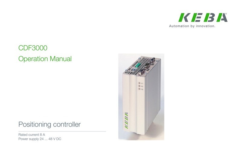
Keba KeContact M20 User manual

KeContact
M20
Expanded charging management
Operating manual V 1.02
Translation of the original instructions

Document:V 1.02
Filename: KeContactM20_en.pdf
Pages: 64
© KEBA 2022
Specifications are subject to change due to further technical developments. Details presented may be
subject to correction.
All rights reserved.
KEBA Energy Automation GmbH Reindlstraße 51, 4040 Linz, Austria, www.keba.com/emobility
For information about KEBA and our subsidiaries please look at www.keba.com.

M20 Table of contents
V1.02 3
© KEBA 2022
Table of contents
1 Introduction................................................................................................................ 5
1.1 Representation of safety instructions............................................................... 5
1.2 Purpose of the document................................................................................. 6
1.3 Requirements................................................................................................... 6
1.4 Warranty .......................................................................................................... 7
1.5 Notes on this document ................................................................................... 7
1.6 Further documentation..................................................................................... 7
2 System overview ....................................................................................................... 8
2.1 Network interfaces ........................................................................................... 10
2.2 Structure of a local charging network............................................................... 12
3 Description................................................................................................................. 15
3.1 Front view ........................................................................................................ 15
3.2 Rear view......................................................................................................... 15
3.3 Type plate ........................................................................................................ 16
3.4 Accessories / Spare parts................................................................................ 16
4 Displays and operating elements ............................................................................ 17
4.1 Status LED....................................................................................................... 17
4.2 Power button.................................................................................................... 17
4.3 Reset button..................................................................................................... 17
5 Mounting and installation instructions ................................................................... 18
5.1 General instructions......................................................................................... 18
5.2 ESD information............................................................................................... 18
5.3 Inserting the SIM card...................................................................................... 19
5.4 Space requirement........................................................................................... 22
5.5 Installation in the control cabinet...................................................................... 23
5.6 Wall installation................................................................................................ 25
5.7 Removing......................................................................................................... 26
6 Connections and wiring............................................................................................ 27
6.1 Power supply ................................................................................................... 27
6.2 USB port .......................................................................................................... 27
6.3 Ethernet interface............................................................................................. 28
6.4 Graphic interface.............................................................................................. 28
6.5 Antenna............................................................................................................ 29
7 Configuration ............................................................................................................. 31
7.1 Enabling the DHCP server............................................................................... 31

M20Table of contents
V1.02
4
© KEBA 2022
7.2 Configuration in series via USB stick............................................................... 32
8 Web interface ............................................................................................................. 36
8.1 Main menu ....................................................................................................... 37
8.2 User menu ....................................................................................................... 42
9 Functions ................................................................................................................... 44
9.1 Load management in the local charging network ............................................ 44
9.2 RFID authorization........................................................................................... 45
9.3 OCPP backend ................................................................................................ 47
9.4 Smart Home Interface...................................................................................... 49
9.5 Integration of external meters .......................................................................... 49
10 Maintenance............................................................................................................... 52
10.1 Diagnosis and troubleshooting......................................................................... 52
10.2 Software update............................................................................................... 52
11 Technical data............................................................................................................ 54
11.1 General ............................................................................................................ 54
11.2 Power supply ................................................................................................... 54
11.3 Ambient conditions........................................................................................... 54
11.4 Interfaces Embedded PC................................................................................. 54
11.5 LTE antenna .................................................................................................... 55
11.6 Dimensions, weight.......................................................................................... 55
12 EU directives and standards .................................................................................... 57
13 UKCA .......................................................................................................................... 58
14 EC Declaration of Conformity .................................................................................. 59
Index ........................................................................................................................... 61

M20 Introduction
V1.02 5
© KEBA 2022
1 Introduction
This document describes an expanded charging network with the following
devices:
● KeContact M20 master device (embedded PC with power adapter and
LTE antenna)
● Compatible client devices (P30 c-series)
The device variant can be read off based on the product designation on the
type plate. The software version can be read out via the web interface. For
more specific information on the client devices, see the respective "Operat-
ing Instructions".
The pictured devices used in this manual are visual examples. The figures
and explanations contained in this manual refer to a typical device design.
The devices used by you may differ in their appearance.
1.1 Representation of safety instructions
At various points in this manual, you will see notes and precautionary warn-
ings regarding possible hazards. The symbols used have the following
meaning:
DANGER!
indicates an imminently hazardous situation, which will result in death or se-
rious bodily injury if the corresponding precautions are not taken.
WARNING!
indicates a potentially hazardous situation, which can result in death or seri-
ous bodily injury if the corresponding precautions are not taken.
CAUTION!
means that if the corresponding safety measures are not taken, a potentially
hazardous situation can occur that may result in slight bodily injury.
Caution
means that damage to property can occur if the corresponding safety mea-
sures are not taken.
ESD
This symbol reminds you of the possible consequences of touching electro-
statically sensitive components.

M20Introduction
V1.02
6
© KEBA 2022
Information
Identifies practical tips and useful information. No information that warns
about potentially dangerous or harmful functions is contained.
1.2 Purpose of the document
This document describes the installation and configuration of the expanded
KeContact M20 functions. This includes the description of settings in the
web interface.
WARNING!
Risk of electric shock to persons!
In addition to this document, all information in the description of the power
adapter, which is in the power adapter packaging, must be observed.
Information
If the description included with the power adapter cannot be read and un-
derstood due to the available languages, then use the description in the re-
quired language from the homepage of the manufacturer.
1.3 Requirements
This document contains information for persons with the following require-
ments:
Target group Required knowledge and abilities
Electrician
Person who, due to his or her special training, expertise and experi-
ence as well as knowledge of current standards, is able to assess
the work performed and the possible hazards.
Knowledge of:
● current valid safety information,
● the mode of operation of the charging station,
● the displays and operating elements of the charging station,
● basics of network technology,
● basics of IT,
● diagnostic options,
● systematic fault analysis and rectification,
● the setting options on the charging station.

M20 Introduction
V1.02 7
© KEBA 2022
1.4 Warranty
Only general maintenance work that is expressly permitted by KEBA may be
performed. Any other tampering to the device will result in a loss of the war-
ranty claim.
1.5 Notes on this document
The manual is part of the product. It is to be retained over the entire life cycle
of the product and should be forwarded to any subsequent owners or users
of the product.
The instructions contained in this manual must be followed precisely. Failure
to do so could result in the creation of potential sources of danger or the dis-
abling of safety devices. Apart from the safety instructions given in this man-
ual, the safety precautions and accident prevention measures appropriate to
the situation in question must also be observed.
1.5.1 Contents of the document
● Installation and configuration of the expanded KeContact M20 functions
1.5.2 Not contained in this document
● Installation and deinstallation of client charging stations
● Operating behavior of the client charging stations
● Configuration of the client charging stations
● Operation of the client charging stations
1.6 Further documentation
Manuals and additional information are available on our website:
www.keba.com/emobility-downloads
Designation Target group
P30 operating instructions ● End customer
● Electricians
P30 installation manual ● Electricians
UDP Programmer's Guide ● Programmer
Modbus TCP Programmers Guide ● Programmer
FAQ
● End customer
● Electricians
● Service technicians

M20System overview
V1.02
8
© KEBA 2022
2 System overview
The KeContact M20 enables control of multiple charging stations. The con-
nection is established over the IT network (switch/router). This makes charg-
ing with an intelligent load management possible. In combination with an up-
stream electricity meter, the entire charging network can be controlled dy-
namically (Modbus TCP).
Only one connection to backend systems is necessary (via OCPP). The
master (KeContact M20) is equipped with different network interfaces for
these functions.
Fig.2-1: System overview (example)
1 ... OCPP backend 2 ... Main distribution
3 ... Sub-distribution 4 ... Charging station
5 ... Switch 6 ... KeContact M20
7 ... Energy meter
a ... Communication interface to operat-
ing company b ... Power connection

M20 System overview
V1.02 9
© KEBA 2022
Cluster
In a cluster consisting of multiple charging stations, the available power re-
serves can be used optimally across the entire system. Up to 200 P30 c-se-
ries (number depending on variant) in max. 15 clusters can be connected
with each other.
Fig.2-2: System overview with cluster (example)
1 ... Cluster 1 2 ... Cluster 2
3 ... Cluster 3
The following chapters describe which network interfaces are provided and
how to set up a network.

M20System overview
V1.02
10
© KEBA 2022
2.1 Network interfaces
The KeContact M20 provides the following network interfaces (e.g. for con-
nection to an OCPP backend, etc.):
● LAN
● Mobile network (via external antenna & SIM card, 4G/LTE - SIM card re-
quired, M2M SIM card recommended).
Fig.2-3: Configuration overview
1 ... LAN 2 ... Mobile network via SIM
3 ... USB interface
Client charging stations (P30 c-series) can only be connected to the master
(KeContact M20) over LAN. The configuration is done via the web interface
of the master.
Information
WLAN stick (WLAN access point / WLAN hotspot)
● The connection of a WLAN stick to the KeContact M20 is fundamentally
possible, but not recommended. Use at your own risk. In case of prob-
lems, troubleshooting is not assisted by the manufacturer.
● The login data for the first login to the web interface can be taken from
the supplied configuration label as needed.

M20 System overview
V1.02 11
© KEBA 2022
CAUTION!
Danger to life from electromagnetic fields
Before connecting further wireless modules (e.g. WLAN), make sure that
there will not be any out-of-band emission due to interference and that the
limit values for people's exposure to electromagnetic fields are adhered to. It
is recommended that corresponding documentation be included with the
system documentation.
2.1.1 LAN
The master can be connected to a router via the integrated LAN interface.
The router provides a connection to an OCPP backend over the Internet.
1 ... KeContact M20 2 ... Router
3 ... Internet 4 ... OCPP backend
Connection: Ethernet1 connection
Via the LAN interface, the master can also be connected to other client
charging stations, which creates a charging network.

M20System overview
V1.02
12
© KEBA 2022
2.1.2 Mobile network
KeContact M20 has a mobile communications module. It enables a connec-
tion to a OCPP backend via the mobile network. The mobile communications
provider may charge additional fees (depending on the tariff) for running
data transmissions.
Fig.2-4: Mobile network
1 ... KeContact M20 2 ... OCPP backend
For the connection to an external OCPP backend over the mobile network, a
suitable SIM card must be installed during commissioning. When installing
the SIM card, observing the ESD notices is mandatory.
In addition, the mobile network must be activated as the connection to the
OCPP backend and the access data of the mobile service provider must be
set in the configuration (web interface).
Information
The username and password for the mobile network connection must not
be empty and must consist of more than one character!
2.2 Structure of a local charging network
The client charging stations must be connected to the master using a router
or switch.
To enable communication between master and client charging stations, the
devices must be configured in the web interface, see Configuration.
2.2.1 Connection via router or switch
If there are multiple client charging stations, these must be connected to the
master via a router or switch. The connection of the charging station to the
router/switch is made via LAN.

M20 System overview
V1.02 13
© KEBA 2022
Fig.2-5: Connection via router or switch
1 ... Router/Switch 2 ... KeContact M20 (master)
3 ... P30 c-series (client)
Using a router
For a network connection using a router, the router automatically provides
the functionality of a DHCP server in most cases.
Information
If the IP addresses are assigned externally (for example, by routers with ac-
tivated DHCP server), the IP addresses must not be in the following range:
192.168.25.xxx
This address range is reserved for charging stations where the IP address
is set manually via DIP switches.
Using a switch
With a network connection via switch, the DHCP server of the KeContact
M20 (master) must be enabled via the web interface (configuration); it is dis-
abled in the delivery state. IP addresses are then assigned by the KeContact
M20.
2.2.2 Ports for communication in the charging network
For the correct communication in the charging network, the ports below must
be enabled network-internally.
Information
If necessary, contact your network administrator to enable the ports.

M20System overview
V1.02
14
© KEBA 2022
Port Protocol Definition Description
49153 TCP Within the network Socket of the charging station
15118 TCP Within the network Link connection between the charg-
ing stations (SDP)
15118 UDP Within the network Link connection between the charg-
ing stations (SDP)
68 TCP Within the network Transfer of the software update
(Bootps)
68 UDP Within the network Transfer of the software update
(Bootps)
67 TCP Within the network Transfer of the software update
(Bootps)
67 UDP Within the network Transfer of the software update
(Bootps)

M20 Description
V1.02 15
© KEBA 2022
3 Description
3.1 Front view
Fig.3-6: Front view of embedded PC
1 ... VGA* 2 ... COM*
3 ... HDMI/DP* 4 ... Reset button
5 ... Status LED 6 ... Power button
7 ... LTE diversity antenna 8 ... LTE main antenna
*) Connection nonfunctional
3.2 Rear view
Fig.3-7: Rear view of embedded PC
1 ... Ground (GND) 2 ... DC-In
3 ... USB 4 ... Ethernet (LAN)
5 ... COM*
*) Connection nonfunctional

M20Description
V1.02
16
© KEBA 2022
3.3 Type plate
Fig.3-8: Type plate
1 ... Manufacturer 2 ... Manufacturer address
3 ... Product designation 4 ... Material number, serial number
5 ... Technical data 6 ... Production location and date
7 ... Reference to product manual 8 ... ESD notice
9 ... UKCA marking (currently not yet
available)
Information
The CE marking of KEBA Energy Automation GmbH refers exclusively to
the installation of the LTE modem and the SSD as well as the composition
of the system components.
3.4 Accessories / Spare parts
The following accessories/replacement parts can be ordered from KEBA:
Accessories
Name Description Order no.
Wall brackets Brackets for the KeContact M20 wall installa-
tion. 125254
Replacement part
Name Description Order no.
Power adapter Top hat rail power adapter 60W / 24V / 2.5A 125227

M20 Displays and operating elements
V1.02 17
© KEBA 2022
4 Displays and operating elements
4.1 Status LED
The KeContact M20 is equipped with the following LED on the front.
Status LED Description
Dark No SSD/USB activity
Flashing blue SSD/USB activity
4.2 Power button
The power button on the front of the KeContact M20 is backed by a lighting
ring.
LED Description
Dark No supply voltage
Green Device ready for operation
4.3 Reset button
Pressing the reset button on the front triggers a reset of the KeContact M20.

M20Mounting and installation instructions
V1.02
18
© KEBA 2022
5 Mounting and installation instructions
5.1 General instructions
To protect the KeContact M20 from unauthorized access, theft, vandalism
and incorrect configurations, the device must be installed in a lockable envi-
ronment (e.g. lockable control cabinet).
WARNING!
Risk of electric shock to persons!
● The Embedded PC must always be installed safely isolated from electric
circuits with hazardous voltage.
● The power adapter must not be made user accessible.
5.2 ESD information
Electronic component are generally put at risk by electro-static discharges
(Electro Static Discharge). An electro-static charge can occur during any ac-
tivity involving movement. ESD can occur with any touch.
Most discharges are so low that they are not noticeable. However, they can
nevertheless put unprotected electronic components at risk or even destroy
them. Therefore, any handling with open electronics is only permissible with
the application of effective ESD protection.
When handling open electronics, please follow the following ESD measures:
● Only touch open electronics if this is absolutely necessary.
● Wear a conductive ESD wristband.
● Use conductive mats.
● Establish a conductive connection between device/system, mat, wrist-
band, and grounding connection.
● Cotton work clothes are preferred over synthetic fiber materials.
● Keep work area free of highly isolating materials (e.g. Styrofoam, plas-
tics, nylon, ...).
● Use ESD protection even for defective modules.
Always keep the devices in their original packaging and only remove the
packaging immediately before installation.
Avoid, for modules which are mounted in an enclosure, direct contact with
any accessible electronic components, such as non-equipped terminals.

M20 Mounting and installation instructions
V1.02 19
© KEBA 2022
5.3 Inserting the SIM card
ESD
● This product uses components that can be damaged by electrostatic dis-
charge. This symbol reminds you of the possible consequences of
touching electrostatically sensitive components incorrectly. Damage due
to improper handling is not covered by the warranty.
● Open the device only once you have taken appropriate ESD safety mea-
sures. Use a conductive wrist strap in combination with a well-grounded
subsurface. Always discharge static charges from yourself by touching a
bare metal surface connected to the floor or an approved anti-static mat
before touching an ESD-sensitive electronic component.
● Always ensure a clean, ESD-compliant work area, such as approved
anti-static matting.
● Adhere to the ESD information in the chapter "5.2 ESD information".
The slot for the SIM card is located inside the KeContact M20. Tools re-
quired:
● Phillips screwdriver PH1 (not included in the scope of delivery)
● PH00 Phillips screwdriver (included in the scope of delivery)
To insert a SIM card, proceed as follows:
1) Remove the lower housing cover by unscrewing the four screws.
2) Unscrew the screw on the circuit board with the PH00 Phillips screw-
driver.

M20Mounting and installation instructions
V1.02
20
© KEBA 2022
3) Tilt the circuit board upward at an angle (1) and pull it out the front (2).
4) Unlock the SIM card slot by sliding the cover back.
5) Tilt the slot cover back
6) Insert the SIM card. Ensure the correct position.
7) Close the cover again.
Other manuals for KeContact M20
1
Table of contents
Other Keba Controllers manuals
Popular Controllers manuals by other brands

Haier
Haier HW-WA101DBT Operation & installation manual

Derale Perfomance
Derale Perfomance 16797 Nstallation instructions

SOMFY
SOMFY animeo IB+ installation guide

Johnson Controls
Johnson Controls FEC26 Series installation guide

Lenze
Lenze SCL series Installation and operaion manual

Paugge
Paugge ENT-SDVoECON user manual