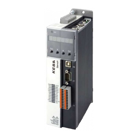
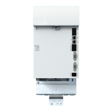
Keba ServoOne Reference guide

ServoOne and
ServoOnejunior
Device Help
Single-Axis Systems and Multi-Axis System
Servo controller 2A to 450A

Description of the Servo controller ServoOne software functionality (Single-Axis
System and Multi-Axis System) as well as ServoOnejunior
ID No.: 0842.26B.5-01
Information valid as of: 08.2020
Effective as of firmware version
lV4.30-xx(ServoOnejunior)
lV4.30-xx(ServoOneSingle-AxisSystemandMulti-AxisSystem)
lV274.30-xx(ifyouneedtousehydraulicparameters,seeSection"Hydraulic
control"onpage175fordetails)
The structure of this help, as well as the screenshots used, were taken from
KeStudioDriveManager5 Version 5.6.
The German version is the original version of this documentation.
ID No.: 0842.26B.5-01Date: 09.2020 ServoOne- Device Help 2

Legalinformation
Subject to technical change without notice.
This Operation Manual has been prepared based on DINEN82079-1. The content
was compiled with the greatest care and attention and reflects thelatest information
available to us.
We should nevertheless point out that this document cannot always be updated in
line with ongoing technical developments in our products.
Information and specifications may be subject to change at any time. For information
on the latest version please visit www.keba.com .
Copyright ©
The entire contents of this documentation, especially the texts, photos and graphics
it contains, are protected by copyright. The copyright is owned by KEBA Industrial
Automation Germany GmbH unless specifically marked otherwise.
ID No.: 0842.26B.5-01Date: 09.2020 ServoOne- Device Help 3
Legal information

Tableofcontents
Legal information 3
Table of contents 4
1 General information 10
1.1 Target Group 10
1.2 Requirements 10
1.3 Pictograms 11
1.4 Exclusion of liability 12
1.5 Applicable documentation 13
1.6 Support 14
2 Safety 15
2.1 Overview 15
2.2 For your own safety 15
2.3 Safety information and warnings 15
2.4 Responsibility 16
3 Initial commissioning 17
3.1 Initial Commissioning wizard 17
3.1.1 Hardware requirements 17
3.1.2 Prompt Initial commissioning 17
3.1.3 Initial commissioning 18
3.2 Automatic test 22
3.3 Motor 23
3.4 Encoder 24
3.5 Control 24
4 Power stage 25
4.1 Power stage settings 25
4.1.1 Voltage supply 26
ID No.: 0842.26B.5-01Date: 09.2020 ServoOne- Device Help 4
Table of contents
4.1.2 Switching frequency 26
4.1.3 Online derating of switching frequency 26
4.1.4 Parameters 26
4.2 Power failure bridging 28
4.2.1 Detection of a voltage failure 28
4.2.2 Monitoring for single-phase failure 31
5 Motor 32
5.1 Motor configuration data 32
5.2 Synchronous motor 33
5.2.1 Synchronous motor electronic data 35
5.3 Linear synchronous motor 36
5.3.1 Linear synchronous motor electronic data 37
5.4 Asynchronous motor 38
5.4.1 Asynchronous motor electrical data 39
5.5 Motor protection 40
5.5.1 Temperature sensors 40
5.5.2 I²t monitoring synchronous motor 43
5.5.3 Asynchronous motor I²t monitoring 44
5.6 Motor identification 45
5.6.1 Synchronous motor identification (rotary and linear) 46
5.6.2 Asynchronous motor identification 46
5.7 Support for motor filters when using PMSM motors 47
5.7.1 General functional description 47
5.7.2 Configuration 48
5.7.3 Parameters 49
5.7.4 Scope signals 50
6 Encoder 51
6.1 Introduction 52
6.1.1 Limiting for EnDat and SSI 52
6.1.2 Encoder gearing 52
6.1.3 Actual values at the encoder channel outputs 53
6.2 Encoder selection 53
6.3 Encoder offset 55
6.4 Connections and pin assignations 55

6.4.1 Connector for resolver (X6) 56
6.4.2 Connector for high-resolution encoders (X7) 56
6.5 Channel 1: Interface X7 59
6.5.1 Main parameters for encoder channel Ch1 60
6.5.2 BiSS(cyclical) X7 61
6.5.3 EnDat (cyclical)X7 62
6.5.4 Hall sensor X7 64
6.5.5 SinCos / TTLX7 64
6.5.6 SSI (cyclical)X7 70
6.5.7 Encoder gearing 72
6.6 Channel 2: Interface X6 74
6.6.1 Compensation for long resolver cables 75
6.6.2 Signal correction GPOC (Gain Phase Offset Correction) 75
6.6.3 Encoder gearing X6 77
6.7 Channel 3: Interface X8 (optional) 78
6.7.1 Main parameters for encoder channel Ch3 82
6.7.2 Absolute value interfaces X8 84
6.7.3 BiSSX8 84
6.7.4 EnDat (cyclical)X8 84
6.7.5 Hall sensor X8 84
6.7.6 SinCos / TTLX8 85
6.7.7 SSI (cyclical) X8 89
6.7.8 HIPERFACEDSL® (ServoOnejunior) 91
6.7.9 Encoder gearing 91
6.8 Channel 4: Virtual encoder 92
6.8.1 Sensorless control synchronous motor 93
6.8.2 Sensorless asynchronous motor control 99
6.9 Redundant encoder 102
6.10 Axis correction 102
6.11 Oversampling 106
6.12 Multi-turn encoder as a single-turn encoder 106
6.13 Increment-coded reference marks 107
6.14 Overflow in multi-turn range 108
6.15 Zero pulse test 109
ID No.: 0842.26B.5-01Date: 09.2020 ServoOne- Device Help 5
Table of contents
7 Control 110
7.1 Overview of control structure 110
7.1.1 Setting 111
7.2 Basic settings 112
7.2.1 Motor control basic settings 112
7.2.2 Automatic inertia detection 114
7.3 Torque controller 115
7.3.1 Current controller optimization 115
7.3.2 Creating the transfer function 116
7.3.3 Decoupling 117
7.3.4 Current actual value filter 117
7.3.5 Detent torque compensation 117
7.3.6 Advanced torque control 127
7.3.7 Torque control with defined bandwidth 131
7.3.8 Enhanced feed forward control of voltage 131
7.4 Speed controller 133
7.4.1 Advanced speed control 135
7.4.2 Digital filter 138
7.4.3 Analysis of Speed control 139
7.5 Position controller settings 142
7.5.1 Pre-control 142
7.5.2 Friction torque compensation (friction) 143
7.6 Asynchronous motor field weakening 145
7.6.1 Variant 1: Default 145
7.6.2 Variant 2: Modified characteristic 146
7.6.3 Voltage controller 146
7.6.4 Field-weakening of asynchronous motor voltage controller 147
7.7 Field weakening and LookUpTable (LUT), synchronous motor 148
7.7.1 Variant 1 (Table) 150
7.7.2 Variant 2 (Calc) 150
7.7.3 Variant 4 (TableMotGen) 151
7.7.4 Variant 5 (TABLE2) 151
7.7.5 Variants 3 and 6 (LUT) 152
7.7.6 Field-weakening of synchronous motor voltage controller 158
7.8 Synchronous motor auto commutation 158
7.8.1 IENCC(1) method 160

7.8.2 LHMES(2) method 161
7.8.3 IECON(4) method 162
7.8.4 Test signal generator 163
7.9 V/Hz mode 167
7.10 Process controller 168
7.10.1 Features 168
7.10.2 Description of control structure 169
7.10.3 Rate Limiter 174
7.10.4 Parameters 174
7.10.5 Scope signals 175
7.11 Hydraulic control 175
7.11.1 Basic setting 175
7.11.2 Pump setting 176
7.11.3 Signal setting 181
7.11.4 Hydraulic Limitations 186
7.11.5 Cylinder configuration 190
7.11.6 Hydraulic Motion profile 192
7.11.7 Pressure control 198
7.11.8 Volumetric flow rate control 200
7.11.9 Speed control 203
7.11.10 Position control 205
7.11.11 Digital filter Hydraulics 209
7.11.12 Example: Configuring an MIO module with 0–20 mA sensors 210
7.11.13 Example: Pressure and pump speed control 211
7.11.14 Example: Hydraulic position control 216
8 Motion profile 224
8.1 Settings 225
8.2 Scaling / Units 226
8.2.1 Standard/CiA 402 227
8.2.2 Sercos 232
8.2.3 User defined 241
8.3 Basic settings 244
8.3.1 PG mode with speed control 244
8.3.2 PG mode with position control 245
8.3.3 IP mode with speed control 246
ID No.: 0842.26B.5-01Date: 09.2020 ServoOne- Device Help 6
Table of contents
8.3.4 IP mode with position control 247
8.3.5 Jerk limitation and speed offset 247
8.3.6 Interpolation 249
8.4 Stop ramps 251
8.5 Homing 252
8.5.1 Homing screen 252
8.5.2 Method (-13): Absolute encoder 254
8.5.3 Method (-12): Set absolute position (absolute measuring system) 255
8.5.4 Method (-10) and Method (-11): Move to block with zero pulse 255
8.5.5 Method (-8) and (-9): Move to block 256
8.5.6 Method (-7) to (0) 257
8.5.7 Method (1) and Method (2): limit switch and zero pulse 258
8.5.8 Method (3) and (4): Positive reference mark and zero pulse 259
8.5.9 Homing methods 5 and 6: Negative reference mark and zero pulse 260
8.5.10 Method (7) to (10): 261
8.5.11 Method (11) to (14): Reference mark, zero pulse and negative limit switch 262
8.5.12 Methods (15) and (16) 264
8.5.13 Method (17) to (30): Reference mark 264
8.5.14 Methods (31) and (32) 265
8.5.15 Method (33) and (34): with zero pulse 266
8.5.16 Method (35) 266
8.6 Jog mode 267
8.6.1 Configuration 267
8.6.2 Digital Inputs 267
8.6.3 Manual mode window, "Jog mode" tab 268
8.7 Reference table 268
8.8 Analogue channel (ISA00 und ISA01) 273
8.8.1 Special characteristics of position control mode 274
8.8.2 Wire Break Monitoring 274
8.9 State machine 276
8.10 Touch probe 278
8.11 Synchronized motion 279
8.11.1 Electronic cam plate 280
8.11.2 Control word for synchronized motion 282
8.11.3 Status word for synchronized motion 282
8.11.4 Master configuration 283
8.11.5 Electronic gearing 286

8.11.6 Engagement 287
8.11.7 Disengagement 288
8.12 Virtual Master 289
8.13 Common master 290
8.14 Cam group (CAM switch) 291
8.14.1 Parametrization of the cam group 291
8.14.2 Parameters 295
8.14.3 Error messages 299
8.15 Data handling 300
8.16 Analogue channel (IEA05) 301
9 Inputs/Outputs settings 302
9.1 Inputs/Outputs settings 302
9.2 Digital inputs 303
9.2.1 Digital standard inputs 304
9.2.2 Function selectors 305
9.2.3 Hardware enable – power stage 306
9.2.4 Digital virtual inputs 307
9.2.5 Status of the digital inputs 307
9.2.6 Control selector switching 307
9.2.7 Power-up sequence 308
9.2.8 Pulse direction 309
9.3 Digital Outputs 311
9.3.1 Standard digital outputs 311
9.3.2 Function selectors 311
9.3.3 Relay outputs 313
9.3.4 Digital input states 313
9.3.5 Reference reached REF(6) 314
9.3.6 Reference limitation LIMIT(14) 314
9.3.7 Switching with motor contactor 315
9.4 Analogue Inputs 316
9.4.1 Standard analogue inputs 316
9.4.2 Function selectors 317
9.4.3 Analogue input scaling 318
9.4.4 Profile mode and analogue inputs 319
9.4.5 Wire Break Monitoring 319
ID No.: 0842.26B.5-01Date: 09.2020 ServoOne- Device Help 7
Table of contents
9.5 Analogue outputs (option only for ServoOne) 320
9.5.1 Function selectors 320
9.6 Analog output (Option - MIO) 321
9.7 Motor brake output 321
9.7.1 Motor brake details 322
10 Limitations / Thresholds 324
10.1 Settings 324
10.2 Torque- / force limits 325
10.3 Speed- / velocity limits 326
10.4 Position limitation 326
10.5 Power stage 327
11 Alarms & warnings 328
11.1 Warning status 328
11.2 Alarms and warnings (Details) 330
11.3 Warning thresholds 337
11.4 Error display 338
11.4.1 Servo controller display 338
11.4.2 Display in the KeStudioDriveManager5 338
11.5 Error reactions 339
11.6 Error list 342
11.6.1 Error 0: Unknown error 342
11.6.2 Error 1: Runtime error 342
11.6.3 Error 2: Parameter list error 344
11.6.4 Error 3: Undervoltage error 348
11.6.5 Error 4: Overvoltage error 348
11.6.6 Error 5: Overcurrent error 349
11.6.7 Error 6: Motor temperature error 353
11.6.8 Error 7: Device heatsink temperature error 355
11.6.9 Error 8: Device inside temperature error 355
11.6.10 Error 9: I2t motor error 356
11.6.11 Error 10: I2t power amplifier error 356
11.6.12 Error 11: External digital input error 357
11.6.13 Error 12: CAN error 358
11.6.14 Error 13: SERCOS error 361

11.6.15 Error 14: EtherCAT error 366
11.6.16 Error 15: Parameter error 368
11.6.17 Error 16: Speed difference error 376
11.6.18 Error 17: Position difference error 377
11.6.19 Error 18: Motion control error 377
11.6.20 Error 19: Fatal error 380
11.6.21 Error 20: Hardware limit switch error 386
11.6.22 Error 21: Initialization, common error 387
11.6.23 Error 22: Encoder channel 1, initialization error 393
11.6.24 Error 23: Encoder channel 2, initialization error 403
11.6.25 Error 24: Encoder channel 3, initialization error 404
11.6.26 Error 25: Encoder cyclic process, common error 410
11.6.27 Error 26: Encoder channel 1, cyclic process error 411
11.6.28 Error 28: Encoder channel 3, cyclic process error 412
11.6.29 Error 30: Control initialization error 413
11.6.30 Error 31: PLC error 416
11.6.31 Error 32: Profibus/Profinet error 417
11.6.32 Error 33: Internal timing error 418
11.6.33 Error 34: Powerfail funkction error 420
11.6.34 Error 35: Encoder monitoring error 421
11.6.35 Error 37: Syncronization controller error 427
11.6.36 Error 38: Braking chopper error 427
11.6.37 Error 39: TWIN monitoring error 427
11.6.38 Error 40: Tech option error 430
11.6.39 Error 41: Fast discharge monitoring error (dc-link) 434
11.6.40 Error 43: Ethernet error 435
11.6.41 Error 44: Wire break, common error 435
11.6.42 Error 45: Lock violation error 436
11.6.43 Error 46: Position limit error 438
11.6.44 Error 47: Functional safety, common error 440
11.6.45 Error 49: Safety system error 442
11.6.46 Error 51: Encoder status, common error 450
11.6.47 Error 52: Analog inputs error 450
11.6.48 Error 53: Motor failure error 450
11.6.49 Error 54: Power grid failure error 451
11.6.50 Error 55: Speed guarding error 451
11.6.51 Error 57: POWERLINK error 452
ID No.: 0842.26B.5-01Date: 09.2020 ServoOne- Device Help 8
Table of contents
11.6.52 Error 58: HYDRAULIK, common error 452
11.6.53 Error 60: Spindle mlamping mystem monitoring error 453
11.6.54 Error 61: End damping error 453
11.6.55 Error 62: Battery buffered encoder 454
11.6.56 Error 63: Error brake monitoring 454
12 Fieldbus 455
12.1 POWERLINK 455
12.2 CANopen/ EtherCAT® 456
12.3 Sercos 456
12.4 PROFIBUS/ PROFINET 457
12.5 Synchronization / Configuration 457
12.6 EDS file generator 458
13 Technology options (X8) 459
13.1 Selection of modules 459
13.2 Second SinCos encoder 460
13.3 SinCos encoder 460
13.4 TTL with encoder simulation 461
13.5 SSI encoder simulation 461
13.5.1 Parameters 461
13.6 DIO option 462
13.7 MIO option 462
13.8 TwinSync 463
14 Device status 464
14.1 Device status 464
14.2 Status bits 465
14.3 Load factor 466
15 Manual mode 467
15.1 Manual mode window 467
15.2 Manual mode control status 471

16 Drive description 472
16.1 Electronic rating plate 472
17 Enhanced/additional functions 477
17.1 Reloading individual parameters 477
17.1.1 Parameters used 477
17.1.2 Parameter list 478
17.1.3 Procedure 479
17.2 Upload and download of parameter data sets 481
17.2.1 Write parameter data set to the file system. 481
17.2.2 Loading the parameter data set from the file system 482
18 Index 483
ID No.: 0842.26B.5-01Date: 09.2020 ServoOne- Device Help 9
Table of contents

1Generalinformation
The product DVD from KEBA Industrial Automation Germany GmbH contains the
complete documentation for the respective product series. The documentation of a
product series includes Operation Manual (hardware description), Device Help
(software description) and other User manuals (e.g. fieldbus description) and
Specifications. These documents are available in PDF format, and some of them are
available in .NET and HTML5 format as well.
1.1TargetGroup
Dear user,
the documentation is an integral part of the device and contains important
information on operation and service. It is aimed at everyone who performs
mounting, set-up, commissioning and service tasks on the product.
1.2Requirements
Important points to be observed when handling the devices from KEBA Industrial
Automation Germany GmbH:
lThedevicedocumentationmustbekeptreadable,alwaysavailable,and
throughouttheproduct’sservicelife.
lReadandunderstandthedocumentationforyourdevice.
lQualification:Toavoidbodilyinjuryandpropertydamage,onlyqualified
personnelwithelectricaltrainingmayworkwith/onthedevice.
lRequiredskillsandknowledge:
-nationalaccidentpreventionrules(e.g.DGUVV3inGermany)
-Howtosetup,install,commissionandoperatethedevice
ID No.: 0842.26B.5-01Date: 09.2020 ServoOne- Device Help 10
1 General information
Work related to other specialised areas, such as transportation, storage and
disposal must be performed exclusively by appropriately trained personnel.
NOTE
lThisDeviceHelpappliestotheServocontrollerServoOneand
ServoOnejunior.Theseinstructionsarenotmeantasa
replacementfortheOperationManualsfortheServoOneor
ServoOnejunior.

1.3Pictograms
The pictograms used in this Device Help have the following meaning for the user:
NOTE
lUsefulinformationorreferencestootherdocuments.
lReferencetofurtherapplicabledocuments.
Step Action
1.
(Number)
HANDLING INSTRUCTIONS
Operating step performed by either the user or the system.
For the pictograms for “safety information and warnings” used in this Device Help,
see the Section "Safety information and warnings" on page 15.
ID No.: 0842.26B.5-01Date: 09.2020 ServoOne- Device Help 11
1 General information

1.4Exclusionofliability
Compliance with the documentation for the devices of KEBA Industrial Automation
Germany GmbH is a prerequisite for:
lsafeoperationand
lattainingtheperformancecharacteristicsandproductcharacteristics
described.
KEBA Industrial Automation Germany GmbH accepts no liability for personal injury,
material damage or financial losses arising from disregard of the documentation.
ID No.: 0842.26B.5-01Date: 09.2020 ServoOne- Device Help 12
1 General information

1.5Applicabledocumentation
All further applicable documents for this device can be found on our website:
www.keba.com under Service -> Support -> DOKU PORTAL
ID No.: 0842.26B.5-01Date: 09.2020 ServoOne- Device Help 13
1 General information

1.6Support
Address :
KEBAIndustrialAutomationGermanyGmbH
Gewerbestrasse5-9
D-35633Lahnau
OurHelplinecanassistyouquicklyandeffectivelyintheeventoftechnicalquestionsonprojectdevelopmentforyourmachineorthecommissioningofyourdevice.
TheHelplinecanbereachedviaemailortelephone:
Openinghours: Mon–Fri:8am–5pm(CET)
Email: helpline@keba.de
Phone: +496441966-180
Internet: www.keba.com
NOTE
lFordetailedinformationonourservices,pleasevisitourwebsite,www.keba.com►Service.
ID No.: 0842.26B.5-01Date: 09.2020 ServoOne- Device Help 14
1 General information

2Safety
2.1Overview
Our devices are designed and built with the latest technology and comply with all
recognized safety rules and standards. Nevertheless, there are potential hazards
that may arise during their use. In this chapter:
lWeprovideinformationregardingtheresidualrisksandhazardsposedby
ourdeviceswhentheyareusedasintended.
lWewarnyouaboutforeseeablemisuseofourdevices.
lWepointoutthatitisnecessarytoexerciseduecareandcautionandgo
overmeasuresdesignedtominimizerisk.
2.2Foryourownsafety
NOTE
lThedevicemustonlybeinstalledandcommissionedin
compliancewiththedocumentationforthecorrespondingdevice
family!
NOTE
lPleasealsopayspecialattentiontothesafetyandwarning
informationintherespectivevalidoperationmanualwhen
commissioningthedrive!
ID No.: 0842.26B.5-01Date: 09.2020 ServoOne- Device Help 15
2 Safety
NOTE
lPayattentiontospecialsafetyandwarninginformationwhichis
providedhereinthedocumentdirectlybeforeaspecificaction
andwarnstheuserofaspecificdanger!
Our devices are designed to be fast and easy to operate. For your own safety and to
ensure reliable operation of your machine, take note of the following:
Step Action
1.
Precautions to avoid injury and damage to property
Ensure there is no possibility of bodily injury or damage to the machine
when testing and commissioning the device. To this end, make sure to
observe Section "Safety information and warnings" on page 15 as well.
2.3Safetyinformationandwarnings
Our devices may pose certain hazards. Accordingly, you must observe the following
safety information and warnings.
WARNING! Risk of injury posed by uncontrolled rotation!
Improper conduct can lead to serious injury or death.
lBeforecommissioningmotorswithfeatherkeyonthe
shaftenditmustbesecuredtopreventitfrombeing
ejected,ifthisisnotpreventedbydriveelementssuch
aspulleys,couplingsorsimilar.

CAUTION! Your system/motor may be damaged if put into operation in
an uncontrolled or inappropriate manner.
Improper conduct can cause damage to your system /
machine.
lBeforethe“Start”step,makeabsolutelysurethatavalid
setpointhasbeenentered,astheconfiguredsetpoint
willbeimmediatelytransmittedtothemotorafterthe
motorcontrolfunctionstarts,whichmayresultinthe
motoracceleratingunexpectedly.
CAUTION! Damage to the device as a result of incorrect operation!
Failure to exercise caution or follow proper working
procedures may result in damage to the device.
lThemainsvoltageforthepowersupplymustnotbe
switchedonuntilaftertheavailablemainsvoltage
settinghasbeenconfiguredinthedevicefirmwareand
thedeviceisrestarted(intheeventthatthemains
voltageortheswitchingfrequencyhasbeenchanged).
2.4Responsibility
Electronic devices are not fail-safe. The company setting up and/or operating a
complete machine or system is responsible:
lForensuringthatthemotorwillbebroughttoasafestateifthedevicefails.
lForthesafetyofpersonsandmachinery.
lForproperfunctionalcapabilityofthecompletemachine.
ID No.: 0842.26B.5-01Date: 09.2020 ServoOne- Device Help 16
2 Safety
lFortheriskassessmentofthecompletemachineorsystemaccordingto
DINEN12100:2011andENISO13849-1.
Observe the topic “Electrical equipment of machines” in IEC/EN60204-1:2006
“Safety of machinery”. The safety requirements defined there to be met by electrical
machinery are intended to ensure personal safety and the safety of machinery or
systems.
The emergency-stop function (to EN60204) shuts down the power supply of a
machine, which leads to uncontrolled rundown of the drives. In order to prevent
hazards, check whether the following will be required:
lKeepingindividualmotorsrunning.
lInitiatingspecificsafetyprocesses.
lIntegratinganemergencystopfunction(emergencystopfunction:stopping
movementby“switchingofftheelectricalpowersupply”orSTOSafeTorque
Off).

3Initialcommissioning
Chapter overview
Pictogram
Navigation ►Projecttree►Devicesetup►Initialcommissioning
Brief description lTheinitialcommissioningforthedrivecanbe
carriedoutwiththehelpofawizard.Thewizard
willtakeyouthroughtheprocessstep-by-step,
ensuringthattheavailableconfigurationoptions
arepresentedinaclearandmanageablemanner.
lThischapterdescribeshowtheinitial
commissioningwizardworks.Thiswizardisused
tosetuptheinitialconfigurationfortheServoOne
andmakeitpossibletomovetheconnected
motor.
Contents 3.1 Initial Commissioning wizard 17
3.2 Automatic test 22
3.3 Motor 23
3.4 Encoder 24
3.5 Control 24
ID No.: 0842.26B.5-01Date: 09.2020 ServoOne- Device Help 17
3 Initial commissioning
3.1InitialCommissioningwizard
The wizard guides you through the subject areas that are relevant for the initial
commissioning. Correct setting of the parameters permits controlled movement of
the drive via the manual mode window (for details see Section "Manual mode" on
page 467). Further settings must be made to exactly adapt the drive system to an
application.
3.1.1Hardwarerequirements
lCorrectassemblyandinstallation,inlinewiththeintendeduse,asperthe
instructionsintheapplicableoperationmanual(seeSection"Applicable
documentation"onpage13).
lVoltagesupplies
o24Vcontrolvoltage
oMainsvoltage
lHardwareenable
oSafeStandstill(ISDSH)
oEnablePower(ENPO)
3.1.2PromptInitialcommissioning
If the KeStudioDriveManager5 is opened without an existing project, a prompt to
undertake initial commissioning appears automatically.

Image 3.1: Prompt to activate wizard
If this window does not open automatically, you can also start the wizard manually
by double-clicking on the pictogram (see “Chapter overview” in Section "Initial
commissioning" on page 17) or via ►Project tree ►Device setup ►Initial
commissioning.
ID No.: 0842.26B.5-01Date: 09.2020 ServoOne- Device Help 18
3 Initial commissioning
3.1.3Initialcommissioning
Image 3.2: Commissioning wizard

Step Subject area Action Instruction
Rotary motor Linear motor
1. Settheswitchingfrequencyandthevoltagesupplyofthepowerstage. Matchingthevoltagesupplytotheclock
frequency
2. Selectthemotortype(P 450[0])
Setthemotortype(P 450[0])to"PSM(1)
=Permanentmagnetsynchronous
motor"
Selectionofmotortype
3. Set(P 490[0])motormovementto“ROT
(0)=rotatingmotor”
Set(P 490[0])motormovementto“LIN
(1)=linearmotor” Selectionofmotorsystem
4.
Identification:
lMeasurementofelectricalparameters(resistance,inductivity)
lCurrentcontrollertuning
lCalculationofnominalflux
Datasetcalculation:
lComplete"Calculationofcontrolsettings"screenandstartthecalculation
Identificationorcalculationofmotordata
set
5.
lSettheI2xtmonitor
lSelectoftemperaturesensor
lCharacteristicsetting
Motorprotection
6. lEncoderselection
lChannelselection Encodersetting
Table 3.1: Instructions for the commissioning wizard
ID No.: 0842.26B.5-01Date: 09.2020 ServoOne- Device Help 19
3 Initial commissioning

Step Subject area Action Instruction
Rotary motor Linear motor
7.
lMotorphasetest
lDetermineencoderoffset
lDeterminemassinertia
Automatictests
8.
Openmanualmodewindow
lControltypeV/Hz(openloop)operation
lMovemotoratlowspeed
lCheckdirection
Motortestinmanualmodewithout
interventionofahigher-levelPLC
9.
lOptimizecurrentcontroller(testsignalgenerator).Whenthereisamotor
datasetthecurrentofthetestsignalgeneratorissetautomatically.
lOptimizingthespeedcontroller
lDeterminemassinertia[J](basicsettings)
lSetspeedfilter:P 0351 CON_SCALC_TF = (0,6 ms)
Recommendation,SinCosencoder0.2ms-0.6ms
Recommendation,resolver:1ms-2ms
Adjustcontrolparameterstosuitthemechanism(setstiffness).
Controllersetting
lCurrentController
lSpeedcontroller
lPositioncontroller
10.
Settings:
lUnits
lReferencesource
lReferenceprocessing
lStopramps
lHomingmethod
Motionprofilesetting
Table 3.1: Instructions for the commissioning wizard (continue)
ID No.: 0842.26B.5-01Date: 09.2020 ServoOne- Device Help 20
3 Initial commissioning
This manual suits for next models
1
Table of contents
Other Keba Controllers manuals
Popular Controllers manuals by other brands

Haier
Haier HW-WA101DBT Operation & installation manual

Derale Perfomance
Derale Perfomance 16797 Nstallation instructions

SOMFY
SOMFY animeo IB+ installation guide

Johnson Controls
Johnson Controls FEC26 Series installation guide

Lenze
Lenze SCL series Installation and operaion manual

Paugge
Paugge ENT-SDVoECON user manual