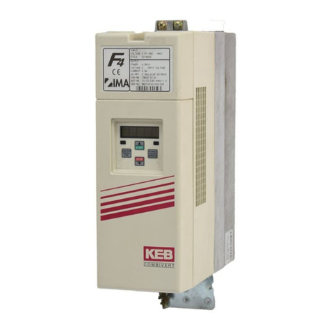
KEBCO COMBIVERT F4-F User manual

3/2003
00.F4.L1B-K300
KEB COMBIVERT F4-F Lift Aufzugstechnik
Version 3.0 (Lift-Servo) Lift Technology
KURZANLEITUNG
QUICK REFERENCE

Diese Betriebsanleitung
– ist gültig für den Frequenzumrichter KEB COMBIVERT F4-F Lift
Version 3.0
– muß jedem Anwender zugänglich gemacht werden
Vor jeglichen Arbeiten muß sich der Anwender mit dem Gerät
vertraut machen. Darunter fällt insbesondere die Kenntnis und
Beachtung der Sicherheits- und Warnhinweise. Lesen Sie des-
halb unbedingt die "Technische DokumentationTeil 1".
This manual
– is valid for frequency inverter KEB COMBIVERT F4-F Lift Version 3.0
– must be made available to every user
Before working with this unit you must familiarize yourself with it.
Pay special attention to the safety and warning guides. Make sure
to read ‘Technical Documentation Part 1’.
DSeite D-3 . . . D-28
GB Page GB-3 . . . GB-28

GB-3
1. Inputs/Outputs................................................................................................... 4
1.1 Terminal X2 - ControlTerminals (units > G-housing) ...............................................4
1.2 Terminal X3 - I/O-Expander (units > G-housing) .......................................................5
1.5 Terminal X2 - ControlTerminals (D- and E-housing) ................................................6
2. Connection......................................................................................................... 7
2.1 Example connection diagram for Lift Inverters > G-housing...................................7
2.2 Example connection diagram for Lift Inverters in D- and E-housing......................8
2.3 Connection X4..............................................................................................................9
2.3.1 Connection Incremental Encoder ..................................................................................9
2.3.2 Connection SIN/COS Encoder ......................................................................................9
2.3.3 Connection Resolver .....................................................................................................9
2.3.4 Connection Hiperface Encoder....................................................................................10
2.3.5 Connection UVW Encoder...........................................................................................10
2.4 Connection X5 - Incremental Encoder Emulation...................................................10
3. Start-Up Instructions........................................................................................11
3.1 Commissioning of an Asychronous Machine with Gearbox..................................11
3.2 Commissioning of a Gearless Permanent Magnet Machine.....................................13
3.3 Commissioning of a Gearless Asychronous Machine ...........................................16
3.4 Commissioning of a Permanent Magnet Machine with Gearbox .............................18
4. Operating Parameter....................................................................................... 20
5. Parameter Lists ............................................................................................... 24
5.1 LF-Parameter..............................................................................................................24
5.2 dr-Parameter ..............................................................................................................26
5.3 EC-Parameter .............................................................................................................27
5.4 An-Parameter .............................................................................................................27
5.5 ru-Parameter ..............................................................................................................28
5.6 In-Parameter...............................................................................................................28
Table of Contents

GB-4
Inputs / Outputs
1.1 Terminal X2 Control Terminals (units > G-housing)
1. Inputs / Outputs
Terminal Function
1 Control Release
2 Reset digital inputs:
3 Direction of travel forward noise immunity: 2 kV
4 Direction of travel reverse logic 1: ± 12…30 V
5 Control Mode internal input resistor: approx. 2 kOhm
6 Door drive active PNP-logic
7 Door drive setpoint input
8 Digital output signal: speed deviation, warning see chapter 3.4
9 Digital output signal: main contactor control inverted see chapter 3.4
10 + 18 V voltage output +18V (+/- 20%) ; max. 20 mA
! When external voltage is connected to
11 Ground for X2.10 and digital inputs/outputs terminal X2.23 then UX2.10 ≈≈
≈≈
≈UX2.23 !
12 +10 V reference voltage +10V (+/- 3%) ; max. 6 mA
13 Ground for analog inputs/outputs
14 Differential voltage input -10V ... +10V
Analog setpoint input resolution:12 Bit Ri = 40 kOhm
15 (see parameter LF.2 and An-parameter) Smoothingtime: 2 ms /processing time: 1...3ms
16 Analog input of the load measure for pretorque Differential voltage input -10V ... +10V
(see parameter LF.30, LF.67 and resolution:12 Bit Ri = 40 kOhm
17 An-parameter) Smoothingtime: 2 ms /processing time: 1...3ms
18 Analog output set speed -10V…+10V / resolution: 8 Bit Ri = 100 Ohm
conditional short-circuit proof ( <1 rpm)
19 Analog output actual speed 0...10V ^0...LF.20
20 30 VDC / 1 A
21 Relay output for cabinet fan control (LF.66) see chapter 6.1
22
23 External voltage supply + 24 ... + 30 V external voltage input
for digital outputs on terminal strip X2

GB-5
Inputs / Outputs
1.2 Terminal X3 I/O-Expander (units > G-housing)
Terminal Function
1 Digital input signal: contactor control (see chapter 3.6) max. voltage endurance to ground: 100 V
2 Setpoint input correction-speed: VBdigital inputs for setpoint activation
3 Setpoint input positioning speed: VE
! only valid with LF.2 = 2 !
4 Setpoint input rated speed: VNmax. voltage endurance to ground: 100 V
5 Setpoint input inspection speed: VI
6 Setpoint input intermediate speed 1: V1terminal assignment with binary coded
7 Setpoint input intermediate speed 2: V2set value selection see LF.2
8
Option ! do not connect !
9 + 24 ... + 30 V external voltage input
External supply voltage
10 for relay outputs on terminal X3
11 Ground for X3.9 / X3.10
12
13 Output signal: ready / overspeed ≈UX3.9 / X3.10 / 500 mA see chapter 3.4
14 Output signal: switching frequency warning ≈UX3.9 / X3.10 / 500 mA see chapter 3.4
15 Output relay contact: braking control 30 V DC / 1 A see chapter 3.4
16
17 Output signal: delay control ≈UX3.9 / X3.10 / 500 mA see chapter 3.4
18 Output relay contact: running open doors 30 V DC / 1 A see chapter 3.4
19
20 Output relay contact: main contactor control 30 V DC / 1 A see chapter 3.4
21
22 Output signal: DCmonitoring ≈UX3.9 / X3.10 / 500 mA see chapter 3.4
23 Output signal: motor temperature warning ≈UX3.9 / X3.10 / 500 mA see chapter 3.4

GB-6
Inputs / Outputs
1.3 Terminal X2 Control Terminals (D- and E-housing)
Terminal Function
1 Control Release
2 Reset digital inputs:
3 Direction of travel forward noise immunity: 2 kV
4 Direction of travel reverse logic 1: ± 12…30 V
5 internal input resistor: approx. 2 kOhm
6 binary-coded setpoint setting (see parameter LF.02) PNP-logic
7
8 Digital output signal: braking control 14...30 V / max. 20mA (per output)
9 Digital output signal: main contactor control PNP-logic
10 + 18 V voltage output +18V (+/- 20%) ; max. 20 mA
! When external voltage is connected to
11 Ground for X2.10 and digital inputs/outputs terminal X2.23 then UX2.10 ≈≈
≈≈
≈UX2.23 !
12 +10 V reference voltage +10V (+/- 3%) ; max. 6 mA
13 Ground for analog inputs/outputs
14 Differential voltage input -10V ... +10V
Analog setpoint input resolution:12 Bit Ri = 40 kOhm
15 (see parameter LF.2 and An-parameter) Smoothingtime: 2 ms /processing time: 1...3ms
16 Analog input of the precontrol torque Differential voltage input -10V ... +10V
(see parameter LF.30, LF.67 and resolution:12 Bit Ri = 40 kOhm
17 An-parameter) Smoothingtime: 2 ms /processing time: 1...3ms
18 Analog output set speed -10V…+10V / resolution: 8 Bit Ri = 100 Ohm
conditional short-circuit proof ( <1 rpm)
19 Analog output actual speed 0...10V ^0...LF.20
20 30 VDC / 1 A
21 Relay: Ready / overspeed see output signal description
22
23 External voltage supply + 24 ... + 30 V external voltage input
for digital outputs

GB-7
Connection
2.1 Example connection diagram for Lift Inverters > G-housing
2. Connection
M
3 ~
X2.1
X2.2
X2.3
X2.4
X2.5
X2.6
X2.7
X3.1
X3.2
X3.3
X3.4
X3.5
X3.6
X3.7
X3.9
X3.10
X2.23
X3.15
X3.16
X3.18
X3.19
X3.20
X3.21
X2.20
X2.21
X2.22
X3.13
X3.14
X3.17
X3.22
X3.23
X2.8
X2.9
X2.11
X3.11
X3.12
Braking resistor
+PA(++) PB PE
U
V
W
PE
L1
L2
L3
EMC-Filter
M
A
I
N
SK1K2
Encoder
X4
to the lift
control
OH
OH
ϑMotor-
PTC ϑ
Encoder X4 (15-pole)
X5 (9-pole)
KEB F4-F
Lift V. 3.0A
KBR
Braking
control +24V
Trigger level for
running open doors to the lift control
Main con-
tactor control K11
+24V
+24V
KFan
+24V
KReady
Ready
Operating frequency warning to the lift control
Deceleration control
DC-monitoring
Motor temp. warning
Speed diviation-
Warning
Main contactor
control inverted
to the lift control
to the lift control
to the lift control
X3.1
Ground GND
*
*
*
*
Direction of travel forward
Direction of travel reverse
Control release
K12
L
I
F
T
-
C
O
N
T
R
O
L
K11 K1K2RST
Control mode
Secondary drive active
Secondary drive setpoint input
Contactor control
KBR K1K2
+24V
X2.9 Correction speed, VB
Positioning speed, VE
Rated speed, VN
Inspection speed, VI
Intermediate speed 1, V1
Intermediate speed 2, V2
+24V
+24V
+24V
To switch off the control
release the auxiliary
contacts of both main
contactorsorarelay(K12),
behind the safety circuit,
must be used.
* All 24 V relays controlled by the frequency
inverter must have diode are suppression.
Heat sink
tempera-
ture level

GB-8
2.2 Example connection diagram for Lift Inverters in D- and E-housing
Connection
M
3 ~
X2.1
X2.2
X2.3
X2.4
X2.5
X2.6
X2.7
X2.23
X2.8
X2.9
X2.20
X2.21
X2.22
X2.11
Braking resistor
PA PB PE
U
V
W
PE
L1
L2
L3
EMC-Filter
M
A
I
N
SK1K2
Encoder
X4
to the lift
control
OH
OH
ϑMotor-
PTC ϑ
Encoder X4 (15-pole)
X5 (9-pole)
KEB F4-F
Lift
KBR
Braking
control
Main con-
tactor control K11
+24V
Ground GND
*
*
Direction of travel forward
Direction of travel reverse
Control release
K12
L
I
F
T
-
C
O
N
T
R
O
L
K11 K1K2RST
Setpoint selection
binary-coded
Setpoint selection
binary-coded
Setpoint selection
binary-coded
+24V
To switch off the control
release the auxiliary
contacts of both main
contactors or a relay (K12),
behind the safety circuit,
must be used.
KReady
*
* All 24 V relays controlled by the frequency
inverter must have diode are suppression.
X2.5 X2.6 X2.7
V = 0 0 0 0
VB100
VE010
VN110
VI001
V1101
V2011
nDoor 111

GB-9
12345 67
8
9
10 1112131415
Theincrementalencoderofthemotorisconnectedtothe15-polesub-
D-socket.
2.3 Connection X4
The connector may only
be connected /
disconnected when the
inverter and voltage
supply are shut off.
Connection
2.3.1Connection
Incremental Encoder
PIN-No. Signal PIN-No. Signal
1- 9B+
2-10-
3 A - 11 + 15 V
4B-12+5V
5 - 13 GND
6-14N-
7-15N+
8 A + Housing Shield
Encoder 1
12345 67
8
9
10 1112131415
PIN-No. Signal PIN-No. Signal
1C- 9B+
2D-10
3A-11
4B-12+5V
5 13 GND
6C+14R-
7D+15R+
8 A + Housing Shield
2.3.2Connection
SIN/COS Encoder
The connector may only
be connected /
disconnected when the
inverter and voltage
supply are shut off.
12345 67
8
9
10 1112131415
PIN-No. Signal PIN-No. Signal
1 9 COS
2 10 SIN_REF
3 SIN_LO 11
4 COS_LO 12
5 SIN_REF_LO 13
614
715
8 SIN Housing Shield
The connector may only be connected / disconnected when
the inverter and voltage supply are shut off.
2.3.3Connection Resolver

GB-10
12345
6789
PIN-No. Signal Meaning
1 A + Signal Channel A
2 B + Signal Channel B
3 reserved
4 + 5 V Voltage output
5 + 24 V external voltage supply
6 A- inverted signal channel A
7 B- inverted signal channel B
8 reserved
9 GND external ground
Housing Shielding
2.4 Connection X5
Incremental Encoder
Emulation
The 9-pole sub-d-socket is used as an incremental encoder output.
Thesignalsareemittedcorrespondingtothesignalsontheincremental
encoder input X4 in RS422 specifications.
Encoder 2
Connection
PIN-No. Signal PIN-No. Signal
1 9 SIN+
2 10 12 V
3 REF_COS 11
4 REF_SIN 12
5 13 GND
6 14 DATA-
7 15 DATA+
8 COS+ Housing Shield
2.3.4Connection
Hiperface Encoder
PIN-No. Signal PIN-No. Signal
1U- 9B+
2V- 10W+
3 A- 11 15 V
4B- 125V
5 W- 13 GND
6U+ 14N-
7V+ 15N+
8 A+ Housing Shield
2.3.5Connection UVW
Encoder
The connector may only be connected / disconnected when
the inverter and voltage supply are shut off.
Theconnectormayonlybeconnected/disconnectedwhenthe
inverter and voltage supply are shut off.

GB-11
Start-Up Instructions
3.1 Commissioning of
an Asynchronous
MachinewithGearbox
3. Start-Up
Instructions
The following procedure is recommended for the commissioning of
theKEBCOMBIVERTF4-Flift version3.0withasynchronous machine
and gearbox:
Adjust the parameters in ascending sequence, as this initiates partial
presettings of the unit. Start with the lift data (LF-parameter). Save
the adjusted data by activating the „Enter key“.
LF.00: Enter password (440)
LF.02: Enter setpoint setting/rotation setting
1 = Binary coded setpoint setting
2 = Input coded setpoint setting
3 = Analog setpoint setting 0...+10V
4 = Analog setpoint setting -10...+10V
LF.04: Check, if the value „0“ is adjusted (asynchronous machine)
LF.20: Enter system speed in m/s
LF.21: Enter the diameter of the traction sheave in mm, if necessary,
remeasure
LF.22: Enter gear reduction, if necessary, count
LF.23: Enter rope suspension (1 for 1:1, 2 for 2:1 etc.)
LF.24: Enter nominal load (lifting capacity) of the cabine in kg
LF.30: Select control procedure (0 = without feedback, 2 = with
feedback)
LF.40: Enter correction speed in m/s
LF.41: Enter crawl speed in m/s
LF.42: Enter rated speed in m/s
LF.43: Enter inspection speed in m/s
dr.00: Enter rated motor power in kW (1 kW = 1.36 PS)
dr.01: Enter rated motor speed in rpm (not synchronous speed)
dr.02: Enter rated motor current in A
dr.03: Enter rated motor frequency in Hz
dr.04: Enter cos phi of the motor
dr.12: Enter rated motor voltage in V (if the value to be adjusted is
already entered, it is essential to acknowledge the value with
ENTER)
EC.01: Enter encoder pulse number
With inspection speed check, whether the lift moves. In case of error
message „E.EnC“ execute an encoder track change with EC.2=1.
Reset the error message through switch off and switch on.

GB-12
Start-Up Instructions
LF.30=0must beadjusted,if themotorshall bedrivenwithoutencoder.
If the load cannot be lifted with this, increase LF.37 (torque increase).
In case of error message „E.OL2“ adjust LF.38=0 (8 kHz operating
frequency).
In case of wrong travel direction (up and down exchanged) activate
the reversal of driving direction with LF.05=1.
The driving comfort can be optimized with the following parameters:
LF.50 Starting jerk in m/s3
LF.51 Acceleration in m/s3
LF.52 Deceleration jerk in m/s3
LF.53 Deceleration in m/s3
LF.54 Stopping jerk in m/s3
The ramps becomes steeper by increasing the values, e.g. the jerk
values becomes harder.
If the cabine rolls back when releasing the brake, increase LF.33 in
steps of 500.
If the lift at the beginning of the drive runs against the brake, increase
LF.70 (brake release time) because the brake release is not fast
enough.
The brake engage time can be increased with parameter LF.79, if the
brake is not closed after stopping when the inverter switches off the
modulation.
If the lift does not reach the rated speed during ‘empty-downward-
drive’ (display LF.90), do the following:
- Set cos phi (dr.04) to 0.9
- Decrease field weakening speed (dr.19) to approx. 2/3 of the
synchronous speed (approx. 1000 rpm with 4-pole motors; approx.
680 rpm with 6-pole motors)
- decrease rated motor speed (dr.01) in steps of 20 until the rated
speed is reached during a downward drive.
Optimization

GB-13
3.2 Commissioning of a
Gearless Permanent
Magnet Machine
Start-Up Instructions
The following procedure is recommended for the commissioning of a
KEB COMBIVERT F4-F lift version 3.0 with a gearless permanent
magnet machine:
Adjust the parameters in ascending sequence, as this initiates partial
presettings of the unit. Start with the selection of the motor and the
resolution and adjustment of the lift data (LF-parameter). Save the
adjusted data by activating the „ENTER key“.
When using a synchronous machine with Hiperface-encoder (inverter
part no. xx.F4.Fxx-xi5x), the motor, encoder and control data are
automatically transferred from the encoder to the inverter at the first
switch on.However, the encoder must be preset with the data.Please
inquire at your motor manufacturer, whether this has been done. If
the data is stored in the encoder, the entire „dr“ and „EC“-parameters
aswellas LF.30- LF.36 neednot tobeentered intheinverter anymore.
LF.00: Enter password (440)
LF.02: Enter setpoint setting/rotation setting
1 = Binary coded setpoint setting
2 = Input coded setpoint setting
3 = Analog setpoint setting 0...+10V
4 = Analog setpoint setting -10...+10V
LF.04: Adjust value “1”
LF.06: Adjust value “1”
LF.20: Enter system speed in m/s
LF.21: Enter the diameter of the traction sheave in mm, if necessary,
remeasure
LF.22: Enter gear reduction 1
LF.23: Enter rope suspension (1 for 1:1, 2 for 2:1 etc.)
LF.24: Enter nominal load (lifting capacity) of the cabine in kg
LF.31 to LF.33: Enter speed controller data (Use pracmatical values
or inquire about adjustment at KEB.)
LF.40: Enter correction speed in m/s
LF.41: Enter crawl speed in m/s
LF.42: Enter rated speed in m/s
LF.43: Enter inspection speed in m/s

GB-14
dr.00: Enter rated motor power in kW
dr.01: Enter rated motor speed in rpm
dr.02: Enter rated motor current in A
dr.03: Enter rated motor frequency in Hz
dr.09: Enter rated motor torque in Nm
dr.17: Enter EMK voltage constant in V/1000 rpm (if only the rated
motor voltage is known, EMK can be calculated according to
following formula: UEMK = UN/ nNx 1000 rpm)
dr.41: Enter winding resistance in Ohm
dr.42: Enter winding inductivity in mH
EC.01: Enter encoder pulse number
EC.04: Enter value „1“ to execute a position alignment and give a
drive command. Cancel drive command, when value „5“ is
displayed. Indoingso makesure thatthemachineisunloaded,
i.e. the ropes may not rest upon the traction sheave.
If the position alignment is successful completed, value „7“ is
displayed.
If the error „E.EnC“ or E.OS“ occurs during the alignment or if
the alignment is not automatically completed, it must be
checked,if themotor cables UVWinverter correspondtoUVW
motor.
If the position of the encoder is known the value can be ente-
red directly as hexadecimal value in EC.07.
Let the motor rotate without ropes and with inspection speed
after the position alignment. If the error message „E.EnC“ or
„E.OS“ occurs during the alignment, check if the motor cables
UVW inverter are correspond to UVW motor, if necessary
change.Theposition alignmentmustbedoneagain ifthemotor
cables are changed.
LF.36: Check the maximum torque in Nm of the motor and, if
necessary, adjust it.
(Attention:Ifthisparameterisadjusted toohigh forsynchronous
machines and if the machine is permanently overloaded, it will
lead to demagnetization of the permanent magnets and the
destruction of the motor!)
With inspection speed check, whether the lift moves.
Start-Up Instructions

GB-15
Start-Up Instructions
In case of error message „E.OL2“ adjust LF.38=0 (8 kHz operating
frequency).
In case of wrong travel direction (up and down exchanged) activate
the reversal of driving direction with LF.05=1.
The driving comfort can be optimized with the following parameters:
LF.50 Starting jerk in m/s3
LF.51 Acceleration in m/s3
LF.52 Deceleration jerk in m/s3
LF.53 Deceleration in m/s3
LF.54 Stopping jerk in m/s3
The ramps become steeper by increasing the values, e.g. the jerk
value becames harder.
If the cabine rolls back when releasing the brake, increase LF.33 in
steps of 500.
If the lift at the beginning of the drive runs against the brake, increase
LF.70 (brake release time) because the brake release is not fast
enough.
The brake engage time can be increased with parameter LF.79, if the
brake is not closed after stopping when the inverter switches off the
modulation.
Optimization

GB-16
Start-Up Instructions
3.3 Commissioning of a
Gearless
Asynchronous
Machine
The following procedure is recommended for the commissioning of
the KEB COMBIVERT F4-F lift version 3.0 with a gearless
asynchronous machine with SinCos-encoder:
Adjust the parameters in ascending sequence, as this initiates partial
presettings of the unit. Start with the selection of the resolution and
the adjustment of the lift data (LF-parameter). Save the adjusted data
by activating the „ENTER key.
LF.00: Enter password (440)
LF.02: Enter setpoint setting/rotation setting
1 = Binary coded setpoint setting
2 = Input coded setpoint setting
3 = Analog setpoint setting 0...+10V
4 = Analog setpoint setting -10...+10V
LF.04: Check, if value „0“ is adjusted
LF.06: Adjust value „1“
LF.20: Enter system speed in m/s
LF.21: Enter diameter of traction sheave in mm, if necessary,
remeasure
LF.22: Enter gear reduction 1
LF.23: Enter rope suspension (1 for 1:1, 2 for 2:1 etc.)
LF.24: Enter nominal load (lifting capacity) of the cabine in kg
LF.30: Select control procedure (0=without feedback, 2=with
feedback, 3=with torque pre-control)
LF.31 to LF.33: Enter speed controller data (use pracmatical values
or inquire about adjustment at KEB)
LF.40: Enter correction speed in m/s
LF.41: Enter crawl speed in m/s
LF.42: Enter rated speed in m/s
LF.43: Enter inspection speed in m/s
LF.54: Due to the high mass moment of inertia, adjust the stopping
jerk as small as possible
(ca. 0,3m/s3)
dr.00: Enter rated motor power in kW (1 kW = 1.36 PS)
dr.01: Enter rated motor speed in rpm (not synchronous speed)
dr.02: Enter rated motor current in A
dr.03: Enter rated motor frequency in Hz
dr.04: Enter cos phi of the motor
dr.12: Enter rated motor voltage in V (if the value to be adjusted is
already entered, it is essential to acknowledge the value with
ENTER)

GB-17
EC.01: Enter encoder pulse number
LF.36: Check the maximum torque in Nm of the motor and, if
necessary, adjust it.
With inspection speed check, whether the lift moves. In case of error
message „E.EnC“ execute an encoder track change with EC.2=1.
Reset the error message through switch off and switch on.
Start-Up Instructions
LF.30=0must beadjusted,if themotor shallbedrivenwithoutencoder.
If the load cannot be lifted with this, increase LF.37 (torque increase).
In case of error message „E.OL2“ adjust LF.38=0 (8 kHz operating
frequency).
In case of wrong travel direction (up and down exchanged) activate
the reversal of driving direction with LF.05=1.
The driving comfort can be optimized with the following parameters:
LF.50 Starting jerk in m/s3
LF.51 Acceleration in m/s3
LF.52 Deceleration jerk in m/s3
LF.53 Deceleration in m/s3
LF.54 Stopping jerk in m/s3
The ramps becomes steeper by increasing the values, e.g. the jerk
values becomes harder.
If the cabine rolls back when releasing the brake, increase LF.33 in
steps of 500.
If the lift at the beginning of the drive runs against the brake, increase
LF.70 (brake release time) because the brake release is not fast
enough.
The brake engage time can be increased with parameter LF.79, if the
brake is not closed after stopping when the inverter switches off the
modulation.
If the lift does not reach the rated speed during ‘empty-downward-
drive’ (display LF.90), do the following:
- Set cos phi (dr.04) to 0.9
- Decrease field weakening speed (dr.19) to approx. 2/3 of the
synchronous speed (approx. 1000 rpm with 4-pole motors; approx.
680 rpm with 6-pole motors)
- decrease rated motor speed (dr.01) in steps of 20 until the rated
speed is reached during a downward drive.
Optimization

GB-18
Start-Up Instructions
3.4 Commissioning of a
Permanent Magnet
MachinewithGearbox
The following procedure is recommended for the commissioning of
the KEB COMBIVERT F4-F lift version 3.0 with permanent magnet
machine and gearbox:
Adjust the parameters in ascending sequence, as this initiates partial
presettings of the unit. Start with the selection of the motor and the
resolution and adjustment of the lift data (LF-parameter). Save the
adjusted data by activating the „Enter key“.
LF.00: Enter password (440)
LF.02: Enter setpoint setting/rotation setting
1 = Binary coded setpoint setting
2 = Input coded setpoint setting
3 = Analog setpoint setting 0...+10V
4 = Analog setpoint setting -10...+10V
LF.04: Adjust value „1“
LF.20: Enter system speed in m/s
LF.21: Enterdiameter ofthe tractionsheave,if necessary,remeasure
LF.22: Enter gear reduction, if necessary, count
LF.23: Enter rope suspension (1 for 1:1, 2 for 2:1 etc.)
LF.24: Enter additional load (lifting capacity, payload) of the cabine in kg
LF.31 to LF.33: Enter speed controller data (use pracmatical values
or inquire about adjustment at KEB)
LF.40: Enter correction speed in m/s
LF.41: Enter crawl speed in m/s
LF.42: Enter rated speed in m/s
LF.43: Enter inspection speed in m/s
dr.01: Enter rated motor speed in rpm
dr.02: Enter rated motor current in A
dr.03: Enter rated motor frequency in Hz
dr.09: Enter rated motor torque in Nm
dr.17: Enter EMK voltage constant in V/1000 rpm (if only the motor
voltageisknown, EMKcan becalculatedaccordingto following
formula: UEMK = UN/ nNx 1000 rpm)
dr.41: Enter winding resistance in Ohm
dr.42: Enter winding inductivity in mH
EC.01: Enter encoder pulse number. (If a resolver is used, the
parameter must not be changed).
EC.04: Enter value „1“ to execute a position alignment and give a
drive command. Cancel drive command, when value „5“ is
displayed. Indoingsomake surethatthemachineis unloaded,
i.e. the ropes may not rest upon the traction sheave.
If the position alignment is successful completed, value „7“ is
displayed.

GB-19
Start-Up Instructions
Optimization
If the error „E.EnC“ or E.OS“ occurs during the alignment or if
the alignment is not automatically completed, it must be
checked,if themotor cables UVWinverter correspondtoUVW
motor.If the position of the encoder is known the value can be
entered directly as hexadecimal value in EC.07.
Let the motor rotate without ropes and with inspection speed
after the position alignment. If the error message „E.EnC“ or
„E.OS“ occurs during the alignment, check if the motor cables
UVW inverter are correspond to UVW motor, if necessary
change.The positionalignmentmustbe doneagainifthe motor
cables are changed.
LF.36: Check the maximum torque in Nm of the motor and, if
necessary, adjust it.
(Attention:Ifthisparameterisadjusted toohigh forsynchronous
machines and if the machine is permanently overloaded, it will
lead to demagnetization of the permanent magnets and the
destruction of the motor!)
With inspection speed check, whether the lift moves.
In case of error message „E.OL2“ adjust LF.38=0 (8 kHz operating
frequency).
In case of wrong travel direction (up and down exchanged) activate
the reversal of driving direction with LF.05=1.
The driving comfort can be optimized with the following parameters:
LF.50 Starting jerk in m/s3
LF.51 Acceleration in m/s3
LF.52 Deceleration jerk in m/s3
LF.53 Deceleration in m/s3
LF.54 Stopping jerk in m/s3
The ramps becomes steeper by increasing the values, e.g. the jerk
values becomes harder.
If the cabine rolls back when releasing the brake, increase LF.33 in
steps of 500.
If the lift at the beginning of the drive runs against the brake, increase
LF.70 (brake release time) because the brake release is not fast
enough.
The brake engage time can be increased with parameter LF.79, if the
brake is not closed after stopping when the inverter switches off the
modulation.

GB-20
X2 Output State
Terminal X2 (upper terminal)
WiththeX.2 outputstateit canbeeasily checked,whethertheoutputs
were set by the inverter control. Every digital output has a specific
value.Ifseveraloutputsaresetatthesametime,thesumofthevalues
is shown.
Value table:
Operating Parameter
Terminal X2 (upper terminal)
With the X.2 input state it can be easily checked, whether the input
signalsreachedtheinvertercontrol.Everyinput(output)hasaspecific
value. If several inputs are set, the sum of the values is shown.
Value Table:
X2 Input State
Example: Inputcontrolrelease(X2.1)anddirectionforward(X2.3)are
triggered with 24V .
Display value: 1+4 = 5
4. OperatingParameter
Display Valency Function Output
Combivis > G D + E terminal
O1 1 digital X2.8
output signal:
braking control
O2 2 digital X2.9
output signal:
main contactor main contactor
control inverted control
O3 4 relay relay ready-to-operate X2.20/X2.22
control cabinet fan collective fault
overspeed
Display Valency Function Input
Combivis > G D + E terminal
ST 1 control release X2.1
RST 2 Reset X2.2
F 4 direction of travel forward X2.3
R 8 direction of travel reverse X2.4
I1 16 control mode X2.5
I2 32 door drive active setpoint selection X2.6
I3 64 door drive setpoint setting binary-coded X2.7
Other manuals for COMBIVERT F4-F
3
Table of contents
Other KEBCO Lifting System manuals
Popular Lifting System manuals by other brands

Aquatic Access
Aquatic Access IGAT-180 AD Installation guide / instruction manual

Stannah
Stannah GOODSMASTER CD User handbook

Jungheinrich
Jungheinrich ECE 220 Standard operating instructions

Maber
Maber MBC2000/150 instructions

SCANCLIMBER
SCANCLIMBER Snake instruction manual

ARTHUR HOLM
ARTHUR HOLM AHDTL user guide