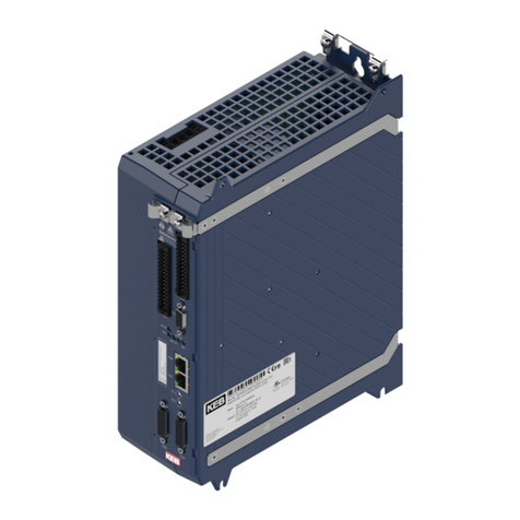
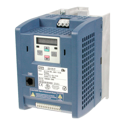
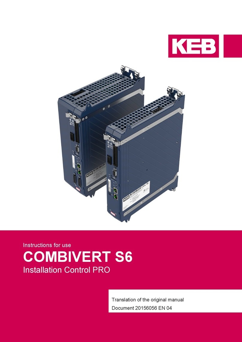
KEBCO COMBIVERT T6APD User manual

COMBIVERT T6APD
INSTRUCTIONS FOR USE
INSTALLATION MODULAR DRIVE CONVERTER SYSTEM
Translation of the original manual
Document 20108384 EN 05


3
PREFACE
Preface
The hardware and software described in this document are products of KEB. The infor-
mation contained in this document is valid at the time of publishing. KEB reserves the
right to update this document in response to misprints, mistakes or technical changes.
Signal words and symbols
Certain procedures within this document can cause safety hazards during the installati-
on or operation of the device. Refer to the safety warnings in this document when per-
forming these procedures. Safety signs are also located on the device where applicable.
A safety warning is marked by one of the following warning signs:
DANGER Dangerous situation, which will cause death or serious injury iif this safe-
ty warning is ignored.
WARNING Dangerous situation, which may cause death or serious injury if this
safety warning is ignored.
CAUTION Dangerous situation, which may cause minor injury if this safety warning
is ignored.
NOTICE Situation, which can cause damage to property if this safety warning is
ignored.
RESTRICTION
Used when the following statements depend on certain conditions or are only valid for
certain ranges of values.
Used for informational messages or recommended procedures.
More symbols
► Thisarrowstartsanactionstep.
• / - Enumerations are marked with dots or indents.
=> Cross reference to another chapter or another page.
Note to further documentation.
www.keb.de/service/downloads

4
PREFACE
Laws and guidelines
KEBAutomationKGconrmswiththeECdeclarationofconformityandtheCEmarkon
the device nameplate that it complies with the essential safety requirements.
The EC declaration of conformity can be downloaded on demand via our website.
Warranty and liability
The warranty and liability on design, material or workmanship for the acquired device is
given in the general sales conditions.
Hereyouwillndourgeneralsalesconditions.
www.keb.de/terms-and-conditions
Furtheragreementsorspecicationsrequireawrittenconrmation.
Support
Although multiple applications are referenced, not every case has been taking into ac-
count. If you require further information or if problems occur which are not referenced in
the documentation, you can request the necessary information via the local KEB agency.
The use of our units in the target products is outside of our control and therefore
lies exclusively in the area of responsibility of the customer.
Theinformationcontainedinthetechnicaldocumentation,aswellasanyuser-specic
advice in spoken and written and through tests, are made to best of our knowledge and
information about the intended use. However, they are regarded as being only informal
and changes are expressly reserved, in particular due to technical changes. This also
applies to any violation of industrial property rights of a third-party. Selection of our units
in view of their suitability for the intended use must be done generally by the user.
Tests can only be done within the intended end use of the product (application) by
the customer. They must be repeated, even if only parts of hardware, software or
the unit adjustment are modied.
Copyright
The customer may use the instructions for use as well as further documents or parts
from it for internal purposes. Copyrights are with KEB and remain valid in its entirety.
This KEB product or parts thereof may contain third-party software, including free and/
or open source software. If applicable, the license terms of this software are contained
in the instructions for use. The instructions for use are already available to you, can be
downloaded free of charge from the KEB website or can be requested from the respec-
tive KEB contact person.
Other wordmarks or/and logos are trademarks (™) or registered trademarks (®) of their
respective owners.

5
TABLE OF CONTENTS
Table of Contents
Preface ....................................................................................................................................................3
Signal words and symbols .............................................................................................................3
More symbols.................................................................................................................................3
Laws and guidelines.......................................................................................................................4
Warranty and liability......................................................................................................................4
Support ........................................................................................................................................4
Copyright........................................................................................................................................4
Table of Contents ...................................................................................................................................5
List of Figures.........................................................................................................................................8
List of Tables ..........................................................................................................................................9
Glossary ................................................................................................................................................10
List of standards ..................................................................................................................................12
1 Basic Safety Instructions............................................ 15
1.1 Target group...................................................................................................................................15
1.2 Transport, storage and proper use .............................................................................................. 15
1.3 Installation......................................................................................................................................16
1.4 Electrical connection ....................................................................................................................17
1.4.1 EMC-compatible installation...............................................................................................18
1.4.2 Voltage test.........................................................................................................................18
1.4.3 Insulation measurement.....................................................................................................18
1.5 Requirements to the entire system..............................................................................................18
1.6 Start-up and operation ..................................................................................................................19
1.7 Maintenance...................................................................................................................................21
1.8 Repair .............................................................................................................................................21
1.9 Disposal..........................................................................................................................................22
2 Product Description .................................................... 23
2.1 T6APD - Principle construction .....................................................................................................25
2.1.1 System architecture............................................................................................................26
2.2 Specied application.....................................................................................................................29
2.2.1 Residual risks.....................................................................................................................29
2.3 Unintended use..............................................................................................................................30
2.4 Overview of the COMBIVERT T6APD ..........................................................................................30
2.5 Nameplate ......................................................................................................................................31
2.6 Congurable options ....................................................................................................................32
2.7 Type code .......................................................................................................................................33

6
TABLE OF CONTENTS
3 Technical Data.............................................................. 34
3.1 Operating conditions ....................................................................................................................34
3.1.1 Evironmental conditions .....................................................................................................34
3.1.2 Mechanical environmental conditions ................................................................................34
3.1.3 Electrical operating conditions............................................................................................35
3.1.3.1 Deviceclassication........................................................................................................35
3.1.3.2 Electromagnetic compatibility..........................................................................................36
3.2 System and module data ..............................................................................................................37
3.2.1 System weight....................................................................................................................37
3.2.2 Electrical system data ........................................................................................................37
3.2.2.1 Operation at the AIC (Active Infeed Controller)...............................................................38
3.2.3 Electrical data High Voltage Interlock Loop (HVIL) ............................................................39
3.2.4 Low Voltage LV-DC input....................................................................................................39
3.2.5 Inverter modules A, B, C ....................................................................................................40
3.2.5.1 Overload characteristic (OL) ...........................................................................................41
3.2.5.2 Frequency-dependent maximum current (OL2) ..............................................................42
3.2.6 Switching frequency and temperature................................................................................44
3.2.7 Cooling and coolant connection .........................................................................................44
3.2.7.1 Pressure drops................................................................................................................46
3.2.7.2 Materials in the cooling circuit .........................................................................................47
3.2.8 Requirements for the coolant .............................................................................................48
3.3 Mechanical data.............................................................................................................................49
3.3.1 Dimensions system length A ..............................................................................................49
3.3.2 Dimensions system length B..............................................................................................50
3.3.3 Dimensions system length C..............................................................................................51
3.3.4 Dimensions system length D..............................................................................................52
3.3.5 Dimensions system length E..............................................................................................53
3.3.6 Dimensions system length F ..............................................................................................54
3.3.7 Connection to the coolant for all housing sizes..................................................................55
4 Installation and Connection........................................ 56
4.1 Mounting ........................................................................................................................................56
4.1.1 Durchsteckmontage ...........................................................................................................57
4.2 Permissible installation position .................................................................................................58
4.2.1 Externalmagneticelds .....................................................................................................59
4.3 Connection of the power unit.......................................................................................................60
4.3.1 High voltage DC supply......................................................................................................60
4.3.1.1 High Voltage Interlock Loop (HVIL) - Exemplary connection ..........................................61
4.3.1.2 Protective earth ...............................................................................................................61
4.3.1.3 HV-DC supply X3A ..........................................................................................................62
4.3.1.4 Coupling for HV-DC supply .............................................................................................63
4.3.2 Motor connection................................................................................................................64

7
TABLE OF CONTENTS
4.3.2.1 Inverter module A and B - socket X1B.............................................................................65
4.3.2.2 Motor connector for inverter module A and B..................................................................66
4.3.2.3 Inverter module C - socket X1B ......................................................................................67
4.3.2.4 Motor connector for inverter module C............................................................................68
4.3.2.5 Motor cable length...........................................................................................................69
4.3.2.6 Interconnection of the motor............................................................................................69
4.3.3 Temperature detection........................................................................................................69
4.3.3.1 Connection of a KTY sensor ...........................................................................................70
4.3.3.2 Connection of a PT1000 sensor......................................................................................70
4.3.3.3 Connection of the temperature input in operating mode PTC.........................................71
4.4 Connection of the control.............................................................................................................72
4.4.1 Assignment of the connector X1A ......................................................................................72
4.4.1.1 Terminal 15 „Enable“ .......................................................................................................74
4.4.1.2 SpecicationoftheCANbus...........................................................................................74
4.4.1.3 Connection example 1 - Connection of the CAN client at T6APD .............................................. 75
4.4.1.4 Connection example 2 - Assignment of both CAN interfaces with T6APD at the end
of the respective bus.....................................................................................................76
4.4.2 Connection plug for X1A.....................................................................................................77
4.4.3 Bus interface X2A...............................................................................................................78
4.4.3.1 Assignment of the Ethernet interface X2A.......................................................................79
5 Certication.................................................................. 80
5.1 ECE R10..........................................................................................................................................80
5.2 Manufacturer´s declaration ..........................................................................................................81
6 Revision History .......................................................... 84

8
LIST OF FIGURES
List of Figures
Figure 1: T6APD - Principle construction .........................................................................................25
Figure 2: T6APD - Complete overview .............................................................................................30
Figure 3: Nameplate........................................................................................................................31
Figure4: AICwith7.2%Ukchokeltering .....................................................................................38
Figure5: AICwithsine-waveEMClter..........................................................................................38
Figure6: Switch-otimetdependingontheoverloadI/IN(OL)withtheexampleofmoduleA.....41
Figure 7: Typical overload characteristic in the lower output frequencies (OL2) Example module A42
Figure 8: Typical pressure drops.....................................................................................................46
Figure 9: Dimensions system length A............................................................................................49
Figure 10: Dimensions system length B............................................................................................50
Figure 11: Dimensions system length C ...........................................................................................51
Figure 12: Dimensions system length D ...........................................................................................52
Figure 13: Dimensions system length E............................................................................................53
Figure 14: Dimensions system length F............................................................................................54
Figure 15: Connection to the coolant ................................................................................................55
Figure 16: Mounting holes.................................................................................................................56
Figure 17: Push-through mounting....................................................................................................57
Figure 18: Permissible installation position.......................................................................................58
Figure19: Externalmagneticelds...................................................................................................59
Figure 20: Connection at DC voltage supply.....................................................................................60
Figure 21: Example of a HVIL wiring.................................................................................................61
Figure 22: Protective earth................................................................................................................61
Figure 23: HV-DC supply X3A (front view on the device)..................................................................62
Figure 24: Coupling for HV-DC supply (counterpart for X3A) ...........................................................63
Figure 25: Wiring between motor and T6APD..........................................................................................................64
Figure 26: Socket inverter module A and B (front view socket).........................................................65
Figure 27: Coupling motor connector for inverter module A and B ...................................................66
Figure 28: Socket inverter module C (front view socket) ..................................................................67
Figure 29: Coupling motor connector for inverter module C .............................................................68
Figure 30: Connection of a KTY sensor............................................................................................70
Figure 31: Connection of a PT1000 sensor ......................................................................................70
Figure 32: Connecting examples temperature input .........................................................................71
Figure 33: Assignment of the terminal block X1A .............................................................................73
Figure 34: Connection of the input terminal 15 „Enable“ ..................................................................74
Figure 35: Connection example 1 of the CAN clients at T6APD.......................................................75
Figure 36: Connection example 2 Assignment of both CAN interfaces with T6APD ........................76
Figure 37: Coupling for control connector X1A .................................................................................77
Figure 38: Bus interface X2A ............................................................................................................78
Figure 39: Bus interface X2A ............................................................................................................78
Figure 40: Declaration of conformity .................................................................................................83

9
LIST OF TABLES
List of Tables
Table 1: System architecture .........................................................................................................28
Table2: Congurableoptions........................................................................................................32
Table 3: Type code ........................................................................................................................33
Table 4: Evironmental conditions...................................................................................................34
Table 5: Mechanical environmental conditions..............................................................................34
Table6: Deviceclassication.........................................................................................................35
Table 7: Electromagnetic compatibility ..........................................................................................36
Table 8: Electrical system data......................................................................................................37
Table 9: System data.....................................................................................................................38
Table 10: Electrical data High Voltage Interlock Loop (HVIL)..........................................................39
Table 11: Electrical data low voltage DC input ................................................................................39
Table 12: Power input of the modules .............................................................................................40
Table 13: Electrical data of the inverter modules.............................................................................40
Table 14: Frequency-dependent maximum current for module A....................................................43
Table 15: Frequency-dependent maximum current for module B....................................................43
Table 16: Frequency-dependent maximum current for module C ...................................................43
Table 17: Switching frequency and temperature .............................................................................44
Table 18: Technical data coolant .....................................................................................................45
Table 19: Electrochemical series / standard potentials against hydrogen.......................................47
Table 20: General requirements for the coolant: .............................................................................48
Table 21: Plug-in connector coding .................................................................................................63
Table 22: Possible applications of temperature detection ...............................................................69
Table23: Specicationofthetemperatureinput .............................................................................70
Table24: Specicationofthetemperatureinput .............................................................................70
Table25: Specicationofthetemperatureinput .............................................................................71
Table26: Specicationsoftheinput„Enable“ .................................................................................74
Table27: SpecicationsoftheCANbus .........................................................................................74
Table 28: PIN description RJ45 Ethernet.........................................................................................79
Table29: CerticationaccordingtoECERegulationNo.10includingAmendment05Supple-
ment 01............................................................................................................................80

10
GLOSSARY
Glossary
AC AC current or voltage
AFE From 07/2019 AIC replaces the pre-
vious name AFE
AFElter From07/2019AIClterreplacesthe
previousnameAFElter
AIC Active Infeed Converter
Ancillary com-
ponents
All ancillary drives of a vehicle, which
eectnotor,atleast,notimmediate-
ly its movement
APD Auxiliaries Power Drives; drive inver-
ter modules
Application The application is the intended use
of the KEB product
ASCL Asynchronous sensorless closed
loop
Attachments For agricultural machinery e.g. ferti-
lizer spreader, tedders or tools: saw,
shredders, etc.
Auto motor
ident.
Automaticallymotoridentication;
calibration of resistance and induc-
tance
AWG American wire gauge
B2B Business-to-business
BAM Broadcast Announced Message
CAN open CAN-based communication protocol
from automation technology
CAN SAE
J1939
SAE J1939 describes the CAN com-
munication in commercial vehicles
COMBIVERT KEB drive converters
COMBIVIS KEB start-up and parameterizing
software
Customer The customer has purchased a KEB
product from KEB and integrates the
KEB product into his product (cus-
tomer product) or resells the KEB
product (dealer)
CV Commercial vehicle
DC DC current or voltage
DCU Drive Control Unit; drive converter
controlboard(drivermware:u/f,
SCL, ASCL)
DIN German Institut for standardization
DM1 J1939 Diagnostic Message Type
Drive inverter
system
Component consisting of several
inverter modules
DS 402 CiADS402-CANdeviceprolefor
drives
ECE regulati-
ons
ECE regulations describe a catalog
of internationally agreed uniform
technical regulations for vehicles,
parts and equipment of motor vehic-
les.
EMC Electromagnetic compatibility
Emergency
stop
Shutdown of a drive in emergency
case (not de-energized)
Emergency
switchingo
Switchingothevoltagesupplyin
emergency case
EN European standard
End customer The end customer is the user of the
customer product
Ethernet Real-timebussystem-denespro-
tocols, plugs, types of cables
EVCU Electronic vehicle control unit
FE Functional earth
Filter DCEMVltersinstalledinallinverter
modules
FU Drive converter
GND Reference potential, ground
HMI Human machine interface (touch
screen)
HV_DC High voltage DC supply (on-board
power supply)
HVAC Heating - Ventilation - Air conditio-
ning
HVIL Hazardous Voltage Interlock Loop
- Protection against unintentional
disconnection of high-voltage plug
connections
Hybrid vehicle Vehiclewith2dierentdrivesour-
ces, e.g. Diesel engine with electric
motor (power via battery, supercaps
etc) or diesel engine with hydraulic
and hydraulic accumulator
Implement Agricultural for the application of an
attachment
Inverter module AC inverter from a drive inverter
system
IP xx Degree of protection (xx for level)
ISOBUS ISOBUSdenesCANapplicationsat
agricultural machinery
IT mains General information for ungrounded
power system. Therefore, insulation
monitoring must be applied as pro-
tective measure
KEB product The KEB product is subject of this
manual
KL15 EN Enable – switched plus from the
ignition starter switch
11
GLOSSARY
KL30 AUX Positive cable directly from the batte-
ry (switched)
KL31 GND Negative cable directly from the
battery or vehicle mass
KTY Silicium temperature sensor (pola-
rized)
Manufacturer The manufacturer is KEB, unless
otherwisespecied(e.g.asma-
nufacturer of machines, engines,
vehicles or adhesives)
MCM American unit for large wire cross
sections
MCU Main Control Unit - Central connec-
tion unit, intelligent control, commu-
nication, diagnostics
Modulation Means in drive technology that the
power semiconductors are controlled
NN Sea level
PE Protective earth
PELV Protective Extra Low Voltage
PLC Programmable Logic Controller
PLC Programmable logic controller
Power on De-
mand
Auxiliary units are only activated
when required - the T6 system
ensuresasuitableandecient
adaptation of voltage, currents and
frequencies
PT1000 TemperaturesensorwithR0=1000Ω
PTC PTC-resistor for temperature detec-
tion
PWM Pulse width modulation
RJ45 Modular connector with 8 lines
SCL Synchronous sensorless closed loop
SELV Safety Extra Low Voltage (< 60V)
SMPS Switched-mode power supply
T6 APD Product designation
UT Utility vehicles
Wizards Plug & play. Innovative user tools
enable fast, intuitive commissioning
and operation of the T6 system

12
LIST OF STANDARDS
List of standards
DGUV regulation 3 Electrical installations and equipment
DIN EN 55012 Vehicles, boats and internal combustion engine driven devices - Radio distur-
bance characteristics - Limits and methods of measurement for the protection
of receivers except those installed in the vehicle/boat/device itself or in adjacent
vehicles/boats/devices (IEC/CISPR 12); German version EN 55012
DIN EN 55025 Radio disturbance characteristics for the protection of receivers used on board
vehicles, boats, and on devices - Limits and methods of measurement (IEC/
CISPR 25); German version EN 55025
DIN EN 60068-2-1 Environmental testing - Part 2-1: Tests - Test A: Cold (IEC 60068-2-1); German
version EN 60068-2-1
DIN EN 60068-2-2 Environmental testing - Part 2-2: Tests - Test B: Dry heat (IEC 60068-2-2;
German version EN 60068-2-2
DIN EN 60068-2-11 Environmental testing - Part 2: Tests; test Ka: Salt mist (IEC 60068-2-11:1981);
German version EN 60068-2-11
DIN EN 60068-2-14 Environmental testing - Part 2-14: Tests - Test N: Change of temperature (IEC
60068-2-14); German version EN 60068-2-14
DIN EN 60068-2-27 Environmental testing - Part 2-27: Tests - Test Ea and guidance: Shock (IEC
60068-2-27); German version EN 60068-2-27
DIN EN 60068-2-30 Environmental testing - Part 2-30: Tests - Test Db: Damp heat, cyclic (12 h + 12
h cycle) (IEC 60068-2-30); German version EN 60068-2-30
DIN EN 60068-2-31 Environmental testing - Part 2-31: Tests - Test Ec: Rough handling shocks,
primarily for equipment-type specimens (IEC 60068-2-31); German version EN
60068-2-31
DIN EN 60068-2-38 Environmental testing - Part 2-38: Tests - Test Z/AD: Composite temperature/
humidity cyclic test (IEC 60068-2-38); German version EN 60068-2-38
DIN EN 60068-2-52 Environmental testing - Part 2: Tests, Test Kb: Salt mist, cyclic (sodium chloride
solution) (IEC 60068-2-52); German version EN 60068-2-52
DIN EN 60068-2-64 Environmental testing - Part 2-64: Tests - Test Fh: Vibration, broadband random
and guidance (IEC 60068-2-64); German version EN 60068-2-64
DIN EN 60068-2-78 Environmental testing - Part 2-78: Tests - Test Cab: Damp heat, steady state
(IEC 60068-2-78); German version EN 60068-2-78
DIN EN 60529 Degrees of protection provided by enclosures (IP Code) (IEC 60529); German
version EN 60529
DIN EN 60664-1 Insulation coordination for equipment within low-voltage systems - Part 1:
Principles, requirements and tests (IEC 60664-1); German version EN 60664-1
DIN EN 61000-4-2 Electromagnetic compatibility (EMC) - Part 4-2: Testing and measurement
techniques - Electrostatic discharge immunity test (IEC 61000-4-2); German
version EN 61000-4-2
DIN EN 61000-4-3 Electromagnetic compatibility (EMC) - Part 4-3: Testing and measurement
techniques-Radiated,radio-frequency,electromagneticeldimmunitytest(IEC
61000-4-3); German version EN 61000-4-3
DIN EN 61000-4-4 Electromagnetic compatibility (EMC) - Part 4-4:Testing and measurement
techniques - Electrical fast transient/burst immunity test (IEC 61000-4-4);
German version EN 61000-4-4
DIN EN 61000-4-5 Electromagnetic compatibility (EMC) - Part 4-5: Testing and measurement
techniques - Surge immunity test (IEC 61000-4-5); German version EN 61000-4-5
DIN EN 61000-4-6 Electromagnetic compatibility (EMC) - Part 4-6: Testing and measurement
techniques - Immunity to conducted disturbances, induced by radio-frequency
elds(IEC61000-4-6);GermanversionEN61000-4-6

13
LIST OF STANDARDS
DIN EN 61131-3 Programmable controllers - Part 3: Programming languages (IEC 61131-
3:2013); German version EN 61131-3:2013
DIN EN 61800-3 Adjustable speed electrical power drive systems - Part 3: EMC requirements
andspecictestmethods(IEC61800-3);GermanversionEN61800-3
DIN EN 61800-5-1 Adjustable speed electrical power drive systems - Part 5-1: Safety requirements
- Electrical, thermal and energy (IEC 61800-5-1); German version EN 61800-5-1
DIN EN ISO 4762 Hexagon socket head cap screws (ISO 4762:2004); German version EN ISO
4762:2004
DINIEC 60364-5-54 Low-voltage electrical installations - Part 5-54: Selection and erection of
electrical equipment - Earthing arrangements, protective conductors and protec-
tive bonding conductors (IEC 64/1610/CD:2007)
ECE R10:Rev.5 Uniform provisions concerning the approval of vehicles with regard to electroma-
gnetic compatibility
ECER100:Rev.2 Uniformprovisionsconcerningtheapprovalofvehicleswithregardtospecic
requirements for the electric power train
EN60204-1 Safety of machinery - Electrical equipment of machines - Part 1: General requi-
rements (IEC 44/709/CDV:2014); German version FprEN 60204-1:2014
ISO 11452-1 Road vehicles - Component test methods for electrical disturbances from
narrowband radiated electromagnetic energy - Part 1: General principles and
terminology
ISO 11452-2 Road vehicles - Component test methods for electrical disturbances from
narrowband radiated electromagnetic energy - Part 2: Absorber-lined shielded
enclosure
ISO 11452-4 Road vehicles - Component test methods for electrical disturbances from
narrowband radiated electromagnetic energy - Part 4: Harness excitation methods
ISO 11783-1 Tractors and machinery for agriculture and forestry - Serial control and commu-
nications data network - Part 1: General standard for mobile data communication
ISO 16750-1 Road vehicles - Environmental conditions and testing for electrical and elect-
ronic equipment - Part 1: General
ISO 16750-2 Road vehicles - Environmental conditions and testing for electrical and elect-
ronic equipment - Part 2: Electrical loads
ISO 16750-3 Road vehicles - Environmental conditions and testing for electrical and elect-
ronic equipment - Part 3: Mechanical loads
ISO 16750-4 Road vehicles - Environmental conditions and testing for electrical and elect-
ronic equipment - Part 4: Climatic loads
ISO 16750-5 Road vehicles - Environmental conditions and testing for electrical and elect-
ronic equipment - Part 5: Chemical loads
ISO 20653 Road vehicles - Degrees of protection (IP code) - Protection of electrical
equipment against foreign objects, water and access
ISO6469-3 Electricallypropelledroadvehicles-Safetyspecications-Part3:Protectionof
persons against electric shock
ISO 7637-2 Road vehicles - Electrical disturbances from conduction and coupling - Part 2:
Electrical transient conduction along supply lines only
ISO 7637-3 Road vehicles - Electrical disturbances from conduction and coupling - Part 3:
Electrical transient transmission by capacitive and inductive coupling via lines
other than supply lines
SAE J 1939 Serial Control and Communications Heavy Duty Vehicle Network - Top Level
Document
VDE V 0160-106 Adjustable speed electric power drive systems - Part 6: Guide for determination
of types of load duty and corresponding current ratings (IEC/TR 61800-6:2003);
German version CLC/TR 61800-6:2007

14
LIST OF STANDARDS
VGB R 455 P Water treatment and use of materials in cooling systems
Vo 2015/208 Commission delegated regulation (EU) 2015/208 of 8 December 2014 supple-
menting Regulation (EU) No 167/2013 of the European Parliament and of the
Council with regard to vehicle functional safety requirements for the approval of
agricultural and forestry vehicles

1 Basic Safety Instructions
The COMBIVERT is designed and constructed in accordance with state-of-the-art tech-
nology and the recognized safety rules and regulations However, the use of such de-
vices may cause functional hazards for life and limb of the user or third parties, or dama-
ges to the system and other material property.
The following safety instructions have been created by the manufacturer for the area of
electric drive technology. They can be supplemented by local, country- or application-
specicsafetyinstructions.Thislistisnotexhaustive.Violationofthesafetyinstructions
by the customer, user or other third party leads to the loss of all resulting claims against
the manufacturer.
NOTICE Hazards and risks through ignorance.
►Read the instructions for use !
►Observe the safety and warning instructions !
►If anything is unclear, please contact KEB Automation KG !
1.1 Target group
This instruction manual is determined exclusively for electrical personnel. Electrical per-
sonnelforthepurposeofthisinstructionmanualmusthavethefollowingqualications:
• Knowledge and understanding of the safety instructions.
• Skills for installation and assembly.
• Start-up and operation of the product.
• Understanding of the function in the used machine.
• Detection of hazards and risks of the electrical drive technology.
• Knowledge of DIN IEC 60364-5-54.
• Knowledge of national safety regulations.
15
BASIC SAFETY INSTRUCTIONS
1.2 Transport, storage and proper use
Thetransportiscarriedoutbyqualiedpersonsinaccordancewiththeenvironmental
conditions specied in this manual. The inverter modules shall be protected against
excessive strains.
Transport of drive inverter with an edge length >75 cm
The transport by forklift without suitable tools can cause a deflection of the heat
sink. This leads to premature aging or destruction of internal components.
►Transport of drive inverter on suitable pallets.
►Do not stack drive inverter or load it with other heavy objects.

ESD
Drive controllers contain electrostatic sensitive components.
►Avoid contact.
►Wear ESD-protective clothing.
Do not store drive controllers
• in the environment of aggressive and/or conductive liquids or gases.
• with direct sunlight.
• outside the specified environmental conditions.
16
BASIC SAFETY INSTRUCTIONS
1.3 Installation
DANGER Risk of explosion due to sparking on and in the device!
EX
►When used in an explosive atmospheres, the corresponding re-
quirements must be met.
►Check device connections for tightness to avoid contact resistances
and sparking.
CAUTION Maximum design edges and high weight!
Contusions and bruises!
►Never stand under suspended loads.
►Wear safety shoes.
►Secure drive inverter accordingly when using lifting gear.
To prevent damages to the device:
• The drive inverter must not be opened.
• The device must not be put into operation in case of mechanical defects. Non-com-
pliance with the applicable standards.
• Mountthedriveinverteraccordingtothespecieddegreeofprotection.Position
protected as possible against environmental inuences and mechanical environ-
mental conditions.
• Note installation position and minimum distances to surrounding elements. Select
the largest possible distance to existing heat sources. Do not bend the connection
cable and cooling hoses and secure with strain relief.
• Do not walk-on drive inverter.
• Do not operate the drive inverter without connected cooling circuit.
Vehicles which include drive inverter shall be equipped with additional control and pro-
tective devices in accordance with the relevant applicable safety requirements, e.g. act
respecting technical equipment, accident prevention rules etc. They must always be
complied with, also for drive inverters bearing a CE marking.

17
BASIC SAFETY INSTRUCTIONS
1.4 Electrical connection
DANGER Voltage at the terminals and in the device!
Danger to life due to electric shock!
►Voltages up to DC 820 V and AC 580 V at the connections.
► Foranyworkontheunitswitchothesupplyvoltage,secureit
against switching on and check absence of voltage by measure-
ment.
►All pluggable connection terminals must only be connected or dis-
connected when no voltage is applied.
►Wait until all drives has been stopped in order that no regenerative
energy can be generated.
►Await capacitor discharge time (5 minutes).
►Install suitable protective devices for drive inverters.
►Never bridge upstream protective devices (also not for test purpos-
es).
►Connect the protective earth conductor always to drive inverter and
motor.
►Install all required covers and protective devices for operation.
►Residual current: This product may cause a dc current in the pro-
tective earth conductor. When a residual current protective device
(RCD) or a residual current monitoring device (RCM) is used for the
protection against direct or indirect contact, only a RCD or RCM type
B is permitted on the power supply side of this product.
►Drive inverters with a leakage current >3.5 mA AC current (10mA
DC current) are intended for a stationary connection. Protective
earth conductors must be designed in accordance with the local reg-
ulations for equipment with high leakage currents according to DIN
EN 61800-5-1, EN 60204-1 or DIN IEC 60364-5-54 .
For a trouble-free and safe operation, please pay attention to the following instructions:
• The electrical installation shall be carried out in accordance with ECE R10:Rev.5,
ECE R100:Rev.2 and with the relevant requirements.
• Cable cross-sections and fuses must be dimensioned according to the design of the
machine / vehicle manufacturer.
• The T6APD must be connected via a suitable precharging circuit.
• The minimum cross-section of the protective earth conductor depends on the cross-sec-
tion of the supply cable. A cross-section smaller than 10 mm2Cu or 16 mm2Al is not
permitted.
• The machine / vehicle manufacturer must ensure that the EN requirements are met with
existing or newly wired circuit with safe isolation.
• When using components without isolated inputs/outputs, it is necessary that equi-
potential bonding exists between the components to be connected (e.g. by the equi-
potential line). Disregard can cause destruction of the components by equalizing
currents.
• Observe bending radii for cables and hoses.

18
BASIC SAFETY INSTRUCTIONS
1.4.1 EMC-compatible installation
Observance of the limit values required by EMC law is the responsibility of the customer.
1.4.2 Voltage test
Testing with AC voltage (in accordance with EN 60204-1 Chapter 18.4) may not be
executed, since there is danger for the power semiconductors in the drive inverter.
Additionally the generator will trigger immediately with current error due to the noise
suppression capacitors.
Accordng to EN 60204-1 it is permissible to disconnect already tested com-
ponents. Drive inverters of KEB Automation KG are delivered ex works voltage
tested to 100% according to product standard.
1.4.3 Insulation measurement
An insulation measurement (in accordance with EN 60204-1 Chapter 18.3 for industrial
machines) with DC 500V is permissible, if all power unit connections (grid-connected
potential) and all control connections are bridged with PE.
1.5 Requirements to the entire system
To ensure the electrical safety of the entire system, the following must be observed in
accordance with the requirements of ISO 6469-3:
• The HV-DC/AC circuits must be provided with protective separation or increased
insulation compared to the touchable LV circuits.
• The insulation (separation / barriers / housing) has to be designed by way that its
durability is ensured over the entire service life.
• The test voltages required for the detection of the insulation properties can be
taken from the chapter „3.1 Operating conditions“.
DANGER Personal protection - tasks of the customer!
Danger to life due to electric shock.
►The HV-DC / AC circuits are provided with protective separation
against touchable circuits (= reinforced insulation). This should be
maintainedinthenalapplication!
►Detect faults by installing a suitable protective device (e.g. insulation
monitor)andthenswitcho.

1.6 Start-up and operation
The drive controller must not be started until it is determined that the installation com-
plies with the machine directive; Account is to be taken of EN 60204-1.
WARNING Software protection and programming !
Hazards caused by unintentional behavior of the drive!
►Check especially during initial start-up or replacement of the drive
controller if parameterization is compatible to application.
►Securing a unit solely with software-supported functions is not suf-
cient.Itisimperativetoinstallexternalprotectivemeasures(e.g.
limit switch) that are independent of the drive controller.
►Secure motors against automatic restart.
19
BASIC SAFETY INSTRUCTIONS
The COMBIVERT T6APD system can be adapted to a wide variety of applications by
parameterization. The parameterization is carried out via a main controller (MCU), which
communicates with the individual axis controllers (DCUs). The main controller contains
additionally a freely programmable control unit where the customer can store software
related to his application (customer software). The customer software can already be
installed at KEB on request.
NOTICE Use of customer software in our devices!
►The use of customer software in the target products with regard to
location, purpose and application is outside our control and there-
fore lies exclusivelsy in the area of responsibility of the customer.
►Checks and tests can only be done in combination with the applica-
tion.
► Checksandtestshavetoberepeatedifhardware,rmware,soft-
ware,devicesettingoronlypartsthereofaremodiedbyKEB.
► Thecustomerconrmswithareleasefromliabilitytheresponsibility
for the customer software towards KEB.
The T6APD system has two CAN interfaces whose parameters and behavior can be
freelyconguredinmanyareasbythecustomersoftwareandparameterization.The
writing of the customer software and the examination of the customer software for any
dangers, which could result from it, is the responsibility of the customer and is not owed
by KEB. For these reasons, KEB is not liable for the behavior of the CAN interfaces and
any resulting hazards or damages.

20
BASIC SAFETY INSTRUCTIONS
WARNING
Installation, conguration or program errors can cause malfunc-
tions or total failure of other CAN bus nodes!
►The programming of the customer software must be carried out in
such a way that other CAN bus nodes continue to function in error
case.
►The programming of the customer software must be tested by the
customer in the application.
►Observe cable length and transmission speed.
►Terminate the bus line with terminating resistors.
►The customer assumes the responsibility for the installation, custom-
er software or parameterization.
CAUTION High temperatures at heat sink and coolant!
Burning of the skin!
►Cover hot surfaces safe-to-touch.
►If necessary, attach warning signs on the system.
►Before touching, check the surface and cooling water lines.
►Before working let the unit cool down.
• The supplied plastic cap is only a transport protection.
Degree of protection can only be maintained when connected.
• Use only approved accessories for this device.
• Never touch terminals or cable ends.
Switching at the output
Switching between motor and drive inverter is prohibited for single drives during oper-
ation as this may trigger the protection gear of the device. Function speed search must
be activated if switching can not be avoided. Control release may only be triggered after
closing the motor contactor (e.g. by switching the control release).
Connecting and disconnecting is permissible with multiple motor drives if at least 1 mo-
tor is running during the switch-over process. The drive inverter must be dimensioned to
the occurring starting currents.
Short-circuit resistance
The drive inverters are conditional short-circuit proof. After resetting the internal protec-
tion devices, the function as directed is guaranteed.
Exceptions:
• If an earth-leakage fault or short-circuit often occurs at the output, this can lead to a
defect in the unit.
• If a short-circuit occurs during regenerative operation (2nd or 4th quadrant, regener-
ation into the DC link), this can lead to a defect in the unit.
Table of contents
Other KEBCO Media Converter manuals

KEBCO
KEBCO COMBITRON 91 User manual

KEBCO
KEBCO DUF5ZEM-K010 User manual

KEBCO
KEBCO COMBIVERT 2M.F5.K8F-6009 User manual

KEBCO
KEBCO COMBIVERT F5 User manual

KEBCO
KEBCO COMBIVERT F5 User manual

KEBCO
KEBCO COMBIVERT S6 Series User manual

KEBCO
KEBCO COMBIVERT F5 User manual

KEBCO
KEBCO COMBICOM User manual

KEBCO
KEBCO COMBIVERT F6 User manual

KEBCO
KEBCO COMBIVERT S6 Series User manual
Popular Media Converter manuals by other brands

TV One
TV One 1T-C2-100 Specifications

FOR-A
FOR-A VTW-350HS Operation manual

Black Box
Black Box IC940A-F user manual

Black Box
Black Box LE1502A-R3 Specifications

PULSEEIGHT
PULSEEIGHT P8-HDBT-L-SP4 Quick setup guide

Electronics International Inc
Electronics International Inc EDC-33 Series Operating and installation instructions