Albalá Ingenieros AAC3008C01 User manual

AAC3008C01
QUAD ANALOG AUDIO TO AES/EBU DIGITAL AUDIO CONVERTER
Version 1.0
Albalá Ingenieros, S.A.
Medea, 4 - 28037 Madrid - Spain
23 June 2016 - © Albalá Ingenieros S.A. - All rights reserved

AAC3008C01

AAC3008C01
QUAD ANALOG AUDIO TO AES/EBU DIGITAL AUDIO CONVERTER
Version 1.0
1. DESCRIPTION ...................................................................................................................... 5
1.1. The AAC3008C01 ............................................................................................................................ 5
1.2. Features ............................................................................................................................................. 6
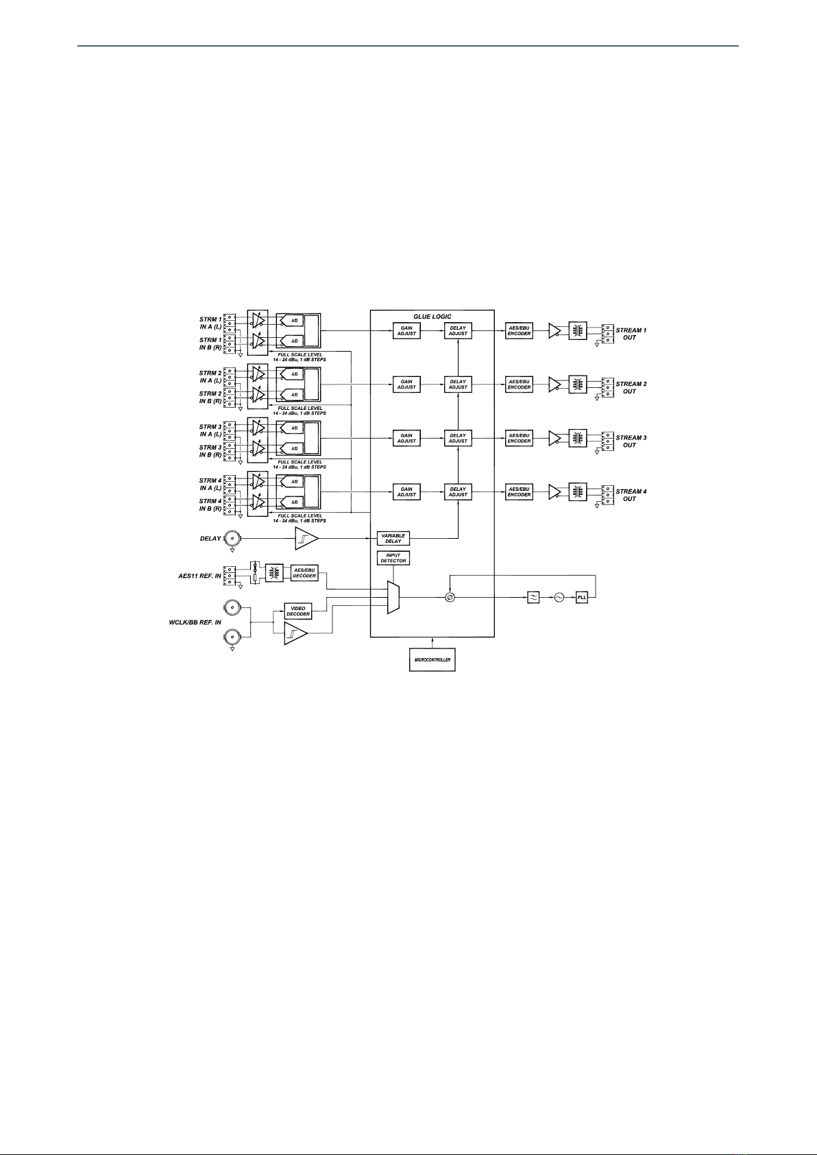
1.3. Block diagram .................................................................................................................................. 8
2. SPECIFICATIONS ................................................................................................................. 9
3. INSTALLATION .................................................................................................................. 11
3.1. Initial inspection .......................................................................................................................... 11
3.2. Safety instructions ...................................................................................................................... 11
3.3. Environmental considerations ................................................................................................ 12
3.4. Power considerations ................................................................................................................. 12
3.5. Module configuration ................................................................................................................ 12
3.6. Installing the module in the mounting frame ................................................................... 12
3.7. Interconnection ............................................................................................................................ 14
3.7.1. Digital audio connections ................................................................................................ 14
3.7.2. Analog audio connections ............................................................................................... 15
3.7.3. Analog video and word-clock connections ................................................................ 15
3.7.4. Delay signal connections .................................................................................................. 15
4. OPERATION ...................................................................................................................... 17
4.1. Front panel description .............................................................................................................. 17
4.2. Functional description ............................................................................................................... 18
4.2.1. Operation in 20 or 24 bits ................................................................................................ 18
4.2.2. Normal and Silence operation ........................................................................................ 19
4.2.3. Description of the delay line ........................................................................................... 19
4.2.4. Selection of the sampling frequency ........................................................................... 20
4.2.4.1. Automatic Mode operation .................................................................................... 20
4.2.4.2. Operation n Manual Mode ..................................................................................... 21
4.3. Description of the processing unit ........................................................................................ 21
4.4. Module remote control and supervision ............................................................................. 22
4.4.1. Details of the AAC3008C01 registers ........................................................................... 23
5. GLOSSARY ........................................................................................................................ 27
6. REGULATIONS .................................................................................................................. 29
7. VERSIONS ......................................................................................................................... 31

AAC3008C01

Albalá Ingenieros | Manual AAC3008C01
1. DESCRIPTION
1.1. The AAC3008C01
The AAC3008C01 module is a high-precision analog-to-digital converter for audio
signals. High SNR A/D converters and a direct digital synthesis (DDS) oscillator that
generate the various clocking signals guarantee very low jitter. The combination of high
quality A/D conversion and a diverse set of external frequency synchronization options
make this module an excellent choice for use in professional quality production
environments.
The AAC3008C01 provides eight analog audio inputs that are coded into four AES/EBU
digital audio data streams. The module implements an internal matrix such that each
digital output can be the sum of one or all of the inputs. Furthermore, each input signal
can be inverted in phase and gained up or down in the digital domain from +24 to
-39.5dB (mute) with a resolution of 0.5dB.
This AAC3008C01 module can be synchronized to three types of external signals: PAL
and NTSC video references (black-burst), audio sampling reference signals (word-clock)
and AES/EBU digital audio reference signals (AES11). If no reference is provided, the
module can operate using an internal reference and generating a sampling frequency
selectable from the following standard values: 32kHz, 44.1kHz, 48kHz, 64kHz, 88.2kHz
and 96kHz.
The module includes memory in order to delay the audio. Each digital stream (each audio
pair) can be configured for an independent delay. Using an external delay input, a
variable delay can be applied to each stream for applications that require
synchronization of audio and video.
The analog audio inputs are electronically balanced with full scale levels that are
adjustable between +14 and +24dBu. The status channel of the digital streams is coded
to indicate that the streams produced are professional quality at 20 or 24 bits.
The front panel of the module contains three classes of LEDs: those that indicate the
presence and lock to external references, those that indicate overloads at either the
analog inputs or the digital outputs and those that indicate the sampling frequency of
the A/D conversion.
The AAC3008C01 uses the following standard sampling frequencies commonly found in
production environments: 32kHz, 44.1kHz, 48kHz, 64kHz, 88.2kHz and 96kHz.
It is possible to monitor the AAC3008C01 status remotely using a communications
controller module installed in the same mounting frame. In addition, certain controller
modules provide SNMP management and the ability to record events in a file including
5

Albalá Ingenieros | Manual AAC3008C01
date and time information for further analysis.
The AAC3008C01 is a TL3000 terminal line module and can be housed in a three rack
unit (3 RU) UR3000 mounting frame or a 1 RU UR3100 mounting frame.
1.2. Features
•High quality converter for transforming eight channels of analog audio into four
channels of AES/EBU digital audio.
• Balanced, high impedance analog audio inputs.
•The AES/EBU digital audio outputs are intended for use with shielded, twisted-pair
cable and are transformer isolated.
• Low jitter sampling clock.
• 24 bit delta-sigma conversion with 64x or 128x oversampling.
• Wide dynamic range.
•Generates the following common sampling frequencies: 32kHz, 44.1kHz, 48kHz,
64kHz, 88.2kHz and 96kHz.
•Provides a digital matrix that can combine the desired input signals into each output
channel.
•Accepts three different reference signal types: black burst, word-clock and AES/EBU
digital audio.
•The AES/EBU reference input is intended for use with shielded, twisted-pair cable and is
transformer isolated.
•Includes a TTL level delay input and a memory buffer that allows each channel to be
delayed by up to 16363 samples.
•Both the sampling frequency and the reference input can be selected manually or
automatically.
• Balanced, high impedance analog audio inputs.
•Front panel indicators for overload in the analog audio inputs, external sync presence
and locking and sampling frequency.
•Full scale level adjustment between +14 and +24dBu in 1dB steps using internal
jumpers.
•Module control and supervision can be done remotely when the mounting frame is
equipped with a communications controller module.
•One UR3000 mounting frame can house up to 12 AAC3008C01 modules. If power
supply redundancy is required and FA3000 or FA3001 modules are used then only 10
modules can be housed in the mounting frame. If PSU3300 or PSU3301 modules are
6

Albalá Ingenieros | Manual AAC3008C01
used for this purpose then up to 12 modules can be installed.
• One UR3100 mounting frame can house up to three AAC3008C01 modules.
• Low power.
7

Albalá Ingenieros | Manual AAC3008C01
1.3. Block diagram
8

Albalá Ingenieros | Manual AAC3008C01
2. SPECIFICATIONS
Analog audio signal input
Connector Plug-in terminal,
3.81mm pitch
Impedance >24 kΩ
Type Active balanced
Number of inputs 4 stereo pairs
Common mode rejection ratio (CMRR):
at 50 Hz >75 dB
at 20 kHz >75 dB
Maximum common mode range ±12 V
Maximum input level 24 dBu
Analog to digital converter
Type Sigma-delta,
x128 oversampling (fs< 48kHz)
Type Sigma-delta,
x64 oversampling (fs> 64kHz)
Number of bits 24
Sampling rate:
Standard 32kHz, 44.1kHz, 48kHz,
64kHz, 88.2kHz and 96 kHz
Full scale level 14 to 24dBu, 1dB steps
3 dB cuttoff frequency:
Lower <20 Hz
Upper 0.49xfs
Noise:
Unweighted <- 107dBFS measured with a 1kHz, -
60dBFS tone
A-weighted <- 110 dBAFS measured with a 1kHz, -
60dBFS tone
Harmonic distortion plus noise (THD+N) <- 91dB measured with a
1kHz, - 1dBFS tone
AES/EBU digital audio signal output
Connector Plug-in terminal,
3.81mm pitch
Impedance 110Ω ± 20 %
Type Transformer balanced
9

Albalá Ingenieros | Manual AAC3008C01
Encoding and electrical characteristics According to
EBU Tech. 3250-E/AES3
standard
Sampling rate 32kHz, 44.1kHz, 48kHz,
64kHz, 88.2kHz and 96 kHz
Number of outputs 4
Signal specifications with external reference:
Jitter <300 psRMS
Locking range ±40 ppm
Signal specifications without external reference:
Maximum frequency error ±25 ppm
Video delay input (TTL signal)
Connector BNC
Impedance 75 Ω
Threshold levels:
VIH min. 2.0 V
VIL max. 0.8 V
Black-burst reference signal input
Connector BNC
Return loss >30dB up to 5 MHz
Type Passive Loop-Through
Signal format According to ITU-R BT.470-6 standard
Accepted formats 625i50, 525i59.94
Input signal amplitude 300mVpp ± 6 dB
AES/EBU digital audio reference signal input
Connector Plug-in terminal,
3.81mm pitch
Impedance Loop-Through or 110Ω loaded
Type Transformer balanced
Encoding and electrical characteristics According to
EBU Tech. 3250-E/AES3
standard
Sampling rate 32kHz, 44.1kHz, 48kHz,
64kHz, 88.2kHz and 96 kHz
Word-clock reference signal input
Connector BNC
Type Passive Loop-Through
Sampling rate 32kHz, 44.1kHz, 48kHz,
64kHz, 88.2kHz and 96 kHz
Input level 2 - 5VPP
General
Maximum power supply current + 600 / - 600 mA
Operating temperature range 0 .. 50 °C
Approximate weight 350 g
10

Albalá Ingenieros | Manual AAC3008C01
3. INSTALLATION
THE AAC3008C01 MODULE CONTAINS ELECTRONIC DEVICES SENSITIVE TO
ELECTROSTATIC DISCHARGE. Always use antistatic bags clearly identified
with a high degree of shielding for storage and transportation.
The AAC3008C01 module is composed of two parts: one AAC3008P01 main board and
one AAC3008P02 rear board. Both parts must be installed in a UR3000 or UR3100
mounting frame following the instructions in the corresponding section of this chapter.
3.1. Initial inspection
Verify that the package has been properly handled during transport. After opening the
packaging, check that one AAC3008P01 main board and one AAC3008P02 rear board are
inside.
You must notify your Albalá Ingenieros distributor or dealer of any damage or defects
observed.
Follow the instructions in this manual to install this module in the mounting frame.
3.2. Safety instructions
•This equipment must be connected to a mains outlet with a protective
earth connection. Never use extension cords that do not have protective
earthing connection. The lack of an effective electrical connection between
the ground pin in the mains input connector of the equipment and the
protective earth of the electrical power distribution can cause serious harm.
•All modules of the Albalá Ingenieros TL3000 terminal line can be
hot-plugged or unplugged without suffering any damage or affecting the
processes that are currently taking place in other modules in the same
mounting frame. When a module is installed in an empty bay of a mounting
frame, it is necessary to mount the rear board that is part of that module.
Prior to installing this board, the mounting frame must be disconnected
from the power supply network. This is required because in addition to the
risk of electrocution for the person handling the device it is possible that a
high instantaneous current coming from the power supply could damage
the connectors and components of the mounting frame and/or the rear
board.
11

Albalá Ingenieros | Manual AAC3008C01
•The AAC3008C01 module and the mounting frame should always be
installed, maintained, operated and removed by personnel with sufficient
technical qualifications. The equipment should never be placed in damp
areas, near splashing liquid, or in explosive or corrosive atmospheres.
Neither modules nor mounting frames can be used in applications that
could endanger human life.
3.3. Environmental considerations
This symbol indicates that this equipment must be deposited at a collection
point for proper waste treatment once it has reached the end of its useful
life.
3.4. Power considerations
The UR3000 and UR3100 mounting frames can house as many AAC3008C01 modules as
will fit in them.
3.5. Module configuration
The AAC3008C01 module has a program jumper for selecting the impedance of the
AES/EBU reference input. This jumper should be set before installing the module in the
mounting frame.
Program jumper J8 has two positions. One position, (110Ω) loads the input with 110Ω,
whereas the second, (LOOP) leaves the input in a high impedance state.
3.6. Installing the module in the mounting frame
The steps needed to install the AAC3008C01 module with the rear board in the
mounting frame are:
1 - Disconnect all power cords from the power supplies of the mounting frame.
2 - Remove the blank panels covering the front and rear of the empty bays chosen for
installing the AAC3008C01 in the mounting frame.
3 - Install the AAC3008P02 rear board ensuring that its 12-pin connectors are properly
aligned with the mounting frame´s mating connectors. Check that the orientation of
the board is correct by looking at the placement of the text printed on it according to
the illustration below.
12

Albalá Ingenieros | Manual AAC3008C01
Details for installation of the module in 3 RU mounting frames
Details for installation of the module in 1 RU mounting frames
4 - Attach the rear board to the mounting frame with two M3 metric screws and tighten.
5 - Verify that the main board is configured according to the user requirements. The
configuration process is detailed later in the INSTALLATION section of this manual.
6 - Insert the AAC3008P01 board (main board of the AAC3008C01 module) into the front
of the mounting frame. The edges of the card slide into two plastic guides inside the
mounting frame.
7 - Affix the main board to the mounting frame using the two screws included on the
front panel.
After these steps, the module is ready to be connected to other equipment.
13

Albalá Ingenieros | Manual AAC3008C01
3.7. Interconnection
The following figure shows the AAC3008C01 module rear board connector layout.
Rear view of the AAC3008C01
The AAC3008C01 module provides eight analog audio inputs (STRM 1 INA(L),STRM 1
INB(R),STRM 2 INA(L),STRM 2 INB(R),STRM 3 INA(L),STRM 3 INB(R),STRM 4 INA(L),STRM 4
INB(R)), four AES/EBU digital audio outputs (STREAM 1 OUT,STREAM 2 OUT,STREAM 3
OUT,STREAM 4 OUT), two inputs for external reference signals (AES11 REF. IN,WCLK/BB
REF. IN) and a delay input (DELAY IN).
The rear interconnection board is not designed to withstand mechanical stress. The
wiring must be fastened properly to the frame where the mounting frame is housed to
prevent the rear board from supporting the weight of the cables.
3.7.1. Digital audio connections
The digital audio reference signal input uses 3.81mm pitch terminal block connectors.
It is balanced and can be set either as loop-through or loaded internally with 110Ω.
14

Albalá Ingenieros | Manual AAC3008C01
Digital audio outputs are balanced, use 3.81mm pitch terminal block connectors and
their characteristic impedance is 110Ω.
For digital audio connections 110Ω characteristic impedance, two-wire shielded cable
is preferred. The GND terminal allows connection of the cable shield.
When used, the AES/EBU reference input with loop-through should be terminated
with 110Ω. This input can be used in loop-through to provide the same reference to
multiple converters. It should be noted that the twisted pair cabling used for the
loop-through has a high-pass frequency response and the maximum number of
AAC3008C01 modules that can be cascaded is ten.
If one of the outputs using twisted pair cabling needs conversion to coaxial cabling as
per AES3id levels then a simple adapter can be built using the following figure.
TWISTED PAIR-TO-COAXIAL OUTPUT ADAPATER BASED ON AES3id
3.7.2. Analog audio connections
Analog audio inputs are high impedance, balanced and use 3.81mm pitch terminal
block connectors. If another termination resistance is required, a resistor with the
desired termination value can be externally mounted between the + and - terminals.
For analog audio connections two-wire shielded cable is preferred. The GND terminal
allows connection of the cable shield.
3.7.3. Analog video and word-clock connections
The analog video and the word-clock inputs are coaxial and provide loop-through
functionality.
Coaxial cabling with a characteristic impedance of 75Ω should be used for the analog
video and word-clock signals.
3.7.4. Delay signal connections
The delay signal cabling is coaxial and terminated by 75Ω.
Coaxial cabling with a characteristic impedance of 75Ω should be used for the delay
signal.
15

Albalá Ingenieros | Manual AAC3008C01
AAC3008C01
16

Albalá Ingenieros | Manual AAC3008C01
4. OPERATION
This section describes the significance of the front panel indicators of the AAC3008C01
module and their remote control and monitoring ability.
4.1. Front panel description
The appearance of the front panel and the elements it contains are shown in the
following illustration.
Front panel of the AAC3008C01
The panel contains the following elements:
17

Albalá Ingenieros | Manual AAC3008C01
In the REFRENCE box:
AES/EBU,
CCVS,
WORD-CLK: Blue. These LEDs indicate a lock to an external reference. When a given
external reference is being used, the corresponding LED lights up. If no
external reference is being used then all three LEDs remain off. If a reference
signal is detected but the internal oscillator is not locked to it, the
corresponding LED blinks.
In the OVERLOAD box:
STREAM 1,
STREAM 2,
STREAM 3,
STREAM 4: Red. These are the overload LEDs, and they can light up for two reasons:
- Clipping: The level of the analog input signal is too high, exceeding the
maximum levels permitted by the input to the AD converter. In this case
the LED lights up continuously.
- Overload: The digital signal at the output has exceeded the established
overload threshold. This threshold comes from the factory set to -1 dBfs
and can be modified using the control software. For overload, the LED
blinks.
In the SAMPLING FREQUENCY box:
48.0kHz,
44.1kHz,
32.0kHz,
Other: Green. These LED indicate the sampling frequency being used for A/D
conversion of the audio. The ''OTHER'' LED lights up is the sampling frequency
is 64kHz, 88.2kHz or 96kHz.
4.2. Functional description
4.2.1. Operation in 20 or 24 bits
The AAC3008C01 can deliver an output stream with the full 24 bits provided by its
A/D converters or it can provide an output with the 20 most significant bits. The
module comes from the factory programmed for 20 bit operation. This configuration
can be changed with the control software.
18

Albalá Ingenieros | Manual AAC3008C01
4.2.2. Normal and Silence operation
The module can deliver a stream of digital silence that can be used as a digital audio
reference signal. The phase noise (jitter) of the AAC3008C01 when using standard
sampling rates is exceptionally low, making it appropriate for use as an AES/EBU
reference signal based upon a black-burst video reference signal or a word-clock
signal.
Silencing of the channels is done via the control software with the corresponding
controls. A change to silence is not instantaneous but instead is done gradually until
the gain is at zero, or silence. These same soft transitions are used whenever the gain
of a given channel is changed.
4.2.3. Description of the delay line
The AAC3008C01 can provide an adjustable delay for each of the four digital audio
output streams. The delay is adjustable in steps of one sample and is set using the
control software. The delay that can be applied is limited by the memory available and
by the sampling frequency.
The external delay reference input (TTL DELAY) can be used to add a variable delay.
When no signal is connected to this input the added delay is 0ms. Calculation of this
variable delay is performed by measuring the time period that the delay signal is at a
logic high. The maximum delay that can be added using this input is 40ms.
The maximum possible delay for each stream, summing the programmed delay plus
the variable delay from the TTL DELAY input corresponds to 16383 samples. The
maximum delay in milliseconds for each sampling frequency is shown in the
following table:
Sampling frequency (kHz) Maximum delay (ms)
32 512
44.1 371
48 341
64 256
88.2 182
96 170
If the sum of the fixed delay and the variable delay exceeds the maximum value, then
the total delay is limited to that maximum.
19

Albalá Ingenieros | Manual AAC3008C01
4.2.4. Selection of the sampling frequency
The AAC3008C01 converter has two operating modes. The first is Automatic Mode, in
which the converter automatically selects the sampling frequency and the reference
input to lock to. The second mode is Manual Mode, where the user selects the
reference input and the sampling frequency.
4.2.4.1. Automatic Mode operation
When the AAC3008C01 operates in Automatic Mode, selection of the reference
source and the sampling frequency is performed automatically. The reference
signal is selected according to the following set of priorities:
- The AES/EBU digital audio reference.
- The black burst video input.
- The word-clock input.
-If no reference signal is available, the AAC3008C01 uses a sampling frequency
of 48kHz and its own internal oscillator.
The AES/EBU digital audio reference input accepts signals with or without audio.
The sampling frequency of this input is used as the reference for the internal
oscillator of the AAC3008C01. In this way all the standard frequencies are
generated: 32kHz, 44.1kHz, 48kHz, 64kHz, 88.2kHz and 96kHz. The PLL of the
AAC3008C01 will not be able to lock to any digital audio reference signals with
sampling rates other than the standard ones listed, and in such cases the
corresponding REFERENCE LED will blink.
The video input accepts signals of 525 or 625 lines. If this input is used as a
reference and the converter is in Automatic Mode then a sampling frequency of
48kHz is generated. The other standard sampling frequencies can be selected
when using Manual Mode.
The word-clock input accepts pulsed signals with TTL levels and whose frequency
must be among the standard values listed. The oscillator of the AAC3008C01 will
not be able to lock to any digital audio reference signals with sampling rates other
than the standard ones listed, and in such cases the corresponding REFERENCE LED
will blink.
The input video reference and the word-clock reference signals use the same
connector. The module can distinguish between the two signal types.
The margin in frequency for proper locking of the AAC3008C01 to reference signals
is ±40ppm.
20
Table of contents
Other Albalá Ingenieros Media Converter manuals

Albalá Ingenieros
Albalá Ingenieros PDS3000C01 User manual

Albalá Ingenieros
Albalá Ingenieros HVM0002C01 User manual

Albalá Ingenieros
Albalá Ingenieros AAD3014C01 User manual

Albalá Ingenieros
Albalá Ingenieros AGW3000C01 User manual

Albalá Ingenieros
Albalá Ingenieros EOP0002C01 User manual

Albalá Ingenieros
Albalá Ingenieros DAD2000C01 User manual

Albalá Ingenieros
Albalá Ingenieros AAD2000C01 User manual

Albalá Ingenieros
Albalá Ingenieros SPL3005C01 User manual

Albalá Ingenieros
Albalá Ingenieros AAD3001C01 User manual

Albalá Ingenieros
Albalá Ingenieros SMC2000C01 User manual