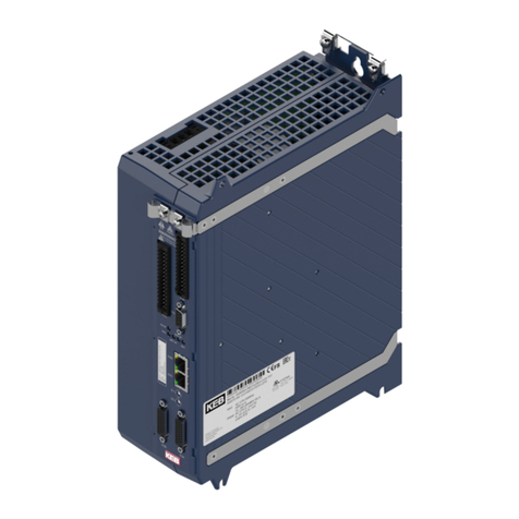
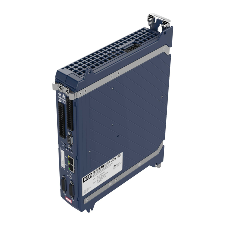
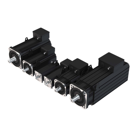
KEBCO COMBIVERT S4 User manual

KEB COMBIVERT S4 Größe D / E
Size D / E
BETRIEBSANLEITUNG
INSTRUCTION MANUAL
07/96
03.S4.01B-K100
ANTRIEBSTECHNIK

Information
The meaning of the pictograms used in this manual is:
Used when life or health of the user are exposed to danger or when
the possibility of severe damage to the material exists.
Observe at all costs!
Special instruction for safe and troublefree operation.
Assistance, Tips
Danger
Warning
Caution
Attention
This instruction manual
– is applicable for the servo system KEB COMBIVERT S4
– must be made available to every user
Before working with this unit the user must familiarize himself
with it. This is especially true concerning knowledge and
observance of the safety and warning guides. Make sure to
read "Technical Dokumentation Part 1".
To ensure an easy handling and commissioning of KEB
COMBIVERT S4 inspite of the extensive programming possibilities
a special operator level has been created in which the most
important parameters are combined. However, if the predefined
parametersarenotsufficienttosolveyourapplicationanApplication
Handbook is available against a small fee
It includes: - creating of an individual operator level
- listing and description of further parameters

E 3
ANTRIEBSTECHNIK
Table of Contents
1. Introduction
1.1 KEB COMBIDYN S4 .....................................E 4
1.2 Part Code ...................................................... E 4
1.3 Application..................................................... E 4
2. Operating Specifications
2.1 Moving or Rotating Parts............................... E 5
2.2 High Operating Temperatures....................... E 5
2.3 Connection Directions ................................... E 5
2.4 Interference Protection of Servo Controller...E 6
2.5 Interference Protection of Electrical Plants ... E 6
2.6 Operating Directions ..................................... E 6
3. Control Cabinet Installation
3.1 Ambient Conditions ....................................... E 7
3.2 Type of Protection ......................................... E 7
3.3 Installation Instructions ................................. E 7
3.4 Calculations .................................................. E 8
3.5 Installation Conditions ................................... E 8
4. Technical Data
4.1 Technical Data 230 V Class.......................... E 9
4.2 Technical Data 400 V Class........................ E 10
4.3 Torque-Speed Characteristics .................... E 12
4.4 Technical Data 230 V / 400 V Class ...........E 16
5. Dimensions
5.1 Dimensions Servo Controller ...................... E 17
5.2 Dimensions Servo Motor............................. E 17
6. Connection
6.1 Survey......................................................... E 18
6.2 1-phase Connection 230 V Class................ E 20
6.3 3-phase Connection 230 / 400 V Class....... E 21
6.4 ConnectionIncrementalEncoderSimulation..... E 22
6.5 Connection Resolver................................... E 22
6.6 Connection SIN/COS Encoder.................... E 23
6.7 Cables.......................................................... E 23
6.8 Control Terminal Strip X2............................ E 24
6.8.1 Digital Inputs / Outputs................................ E 25
6.8.2 Analog Inputs / Outputs............................... E 25
6.8.3 Output Relay ............................................... E 25
6.8.4 External Voltage Supply.............................. E 25
7. Operation
7.1 Parameter Structure.................................... E 26
7.2 Parameter Survey ....................................... E 26
7.3 Selection and Changing of Parameters....... E 27
7.4 Storing Parameter Value............................. E 27
7.5 Error Message ............................................ E 27
8. Parameter Description.............................. E 28
9. Drive Mode
9.1 Setting Possibilities ..................................... E 37
9.2 Condition ..................................................... E 37
9.3 Display and Keyboard ................................. E 37
9.4 Setpoint Display / Setpoint Presetting......... E 37
9.5 Rotation Presetting...................................... E 38
9.6 Start / Stop / Run......................................... E 38
10. Accessories
10.1 Braking Resistor.......................................... E 39
10.1.1 Part Number................................................ E 39
10.1.2 Technical Data ............................................ E 39
10.1.3 Dimensions ................................................. E 39
10.1.4 Connection .................................................. E 39
10.2 Radio Interference Suppression Filter......... E 40
10.2.1 Technical Data ............................................ E 40
10.2.2 Connection .................................................. E 40
10.2.3 Dimensions ................................................. E 40
10.3 Braking Motor.............................................. E 41
10.3.1 Technical Data ............................................ E 41
10.4 Operator...................................................... E 42
11.
Adjustment Assistance Speed Controller ......
E 43
12. Error Diagnosis ......................................... E 44

E 4
1.1 KEB COMBIVERT S4
1. Introduction
The servo system KEB COMBIVERT S4 consists of the components:
–digital servo controller KEB COMBIVERT S4 (230V- or 400V class)
–synchronous servo motor KEB COMBIVERT SM
Thesynchronousservomotorisalsoavailablewith
brake.
Referto"AccessoriesBrakingMotor"(pageE41)
Servo System
Regarding prefabricated motor, resolver and encoder
cables refer to "Accessories Cable " (page E 23).
1.3 Application The digital servo controller KEB COMBIVERT S4 serves exclusively for the control
and regulation of the supplied synchronous servo motor KEB COMBIVERT SM.
The servo system KEB COMBIVERT S4 is a highly dynamic control drive it is
connected and ready for operation within a short time.
1.2 Part Code
03.S4.D20–3001
Sub-assembly 001 = Resolver / Incremental encoder simulation
002 =
Resolver/Inc.enc.sim./Interferencesuppression
003 = ERN1387/Incrementalencodersimulation
004 = ERN 1387 / Inc. enc. sim. / Interf. suppr.
005 = Resolver / Incremental encoder input
006 = Resolver / Inc. enc. inp. / Interf. suppr.
007 = ERN 1387 / Inc. enc. inp.
008 = ERN 1387 / Inc. enc. inp. / Interf. suppr.
Rated speed 1 = 1500 U/min
2 = 2000 U/min
3 = 3000 U/min
4 = 4000 U/min
6 = 6000 U/min
Mechanic construc- 0 = without brake / with featherkey to DIN
tion of the motor 1 = with brake / with featherkey to DIN
2 = without brake / without featherkey
3 = with brake / without featherkey
E = replacement part
Supply voltage 2 = 200 V class
4 = 400 V class
Housing design D or E
Unit designation S4
Unit size M1…M4, 01…04, 11…14, 21…24

E 5
ANTRIEBSTECHNIK
°C
100
Motor housing and braking resistor can attain very high
operating temperatures! Danger of injury!
Prior to any work on the machine (e.g. exchange of tools),
disconnect the machine and secure against unintended
restart!
Safelysecuremovementrangeofmachineduringoperation!
Danger of injury!
• Motor shaft
• Feed axis and parts connected to it
2.1 Moving or Rotating Parts
0
2. Operating Specifications
2.2 High Operating
Temperatures • Housing of servo motor
• Braking resistors
Theconnectionsonthecontrolterminalstripandtheencoder
inputsshowasafeseperationinaccordancewithVDE0100.
The person who sets up the systems or machines must
ensurethattheexistingornewlywiredcircuitmeetstheVDE
requirements for safe seperation.
A trouble-free and safe operation of the servo system is only warranted when the
following connection instructions are observed.
Whendeviated from,malfunctions and damagesmay occur inisolated cases.
– TheservocontrollerKEBCOMBIVERTS4isonlydesignedforafixedconnection.
– Do not interchange power cable and motor line.
– Lay control and power lines separately (min. 10 cm distance).
– Connect control lines only to switching elements and setting devices (relay,
switch, potentiometer), that are suitable for extra-low voltages.
– Use shielded/twisted control lines. Connect the shield only single-sided to PE of
the servo controller.
– Use shielded motor cables. Connect shield to the Servo controller to PE and
extensively connect to motor housing.
– Earth servo controller very well: star-shaped earthing, avoid earth loops,
shortestconnectiontomainearthingterminal.
2.3 Connection Directions

E 6
2. Operating Specifications
2.4 Interference
Protection of Servo
Controller
The control and power inputs of the servo controller are protected
against interferences.
An increased operational reliability and additional protection
againstmalfunctionsisachievedthroughfollowingmeasures:
– Use of mains filter when the mains voltage is affected by the connection of large
consumers (reactive-power compensation equipment, HF-furnaces etc.)
– Protectivewiringofinductiveconsumers(solenoidvalves,relays,electromagnets)
with RC elements or similar devices to absorb the energy released at switch-off.
– Separatelaying ofpowerlinesas describedinthe connection directionstoavoid
inductive and capacitive coupling of interference pulses.
Paired-twisted cables protect against inductive parasitic voltages, shielding
provides protection against capacitive parasitic voltages. Optimal protection is
achievedwithtwistedandshieldedcableswhensignalandpowerlinesarelayed
separately.
The servo controller KEB COMBIVERT S4 transmits waves of high frequency.
Following measures can reduce the arising interference pulses that may effect
electric plants in the vicinity of the servo controller:
– Installation of the servo controller in a metal housing.
– Shielded motor cables.
Theshield must be connected to PE of the servo controller andto the housing of
themotor(connectextensiveshield).Theshieldingshallnotbeusedasprotective
earthing.Onlyanuninterruptedshieldbeginningascloseaspossibleattheservo
controller or servo motor ensures a safe function of the shielding.
– Good earthing (metal-powder tape or 10 mm2earth lead)
– Use of radio interference suppression filters.
2.5 Interference
Protection of
Electric Plants
2.6 Operating Directions
– Install a circuit interrupter between voltage supply and servo controller to permit
the independent switch-off of KEB COMBIVERT S4.
– Frequent switching between mains and servo controller is not permitted!
– Theswitchingbetweenmotorandservocontrollerduringoperationisprohibited!
– The servo system KEB COMBIVERT S4 is to be operated under suitable
conditions (see Ambient Condition).
To avoid premature ageing or destruction of the servo system
KEB COMBIVERT S4 observe the following directions!

E 7
ANTRIEBSTECHNIK
3. Control Cabinet Installation
3.1 Ambient Conditions
Altitude of site max. 3000 m ––
Apowerreductionof1% per
100 m must be taken into account for site altitudes of 1000
m and more above sea level, i.e. 1500mNN = 95% PNominal
Max. permissible Servon Controller Servo Motor
limit values: KEB COMBIVERT S4 KEB COMBIVERT SM
Coolant inlet temper.- /
Ambienttemperature -10 °C…+45 °C -5 °C…+40 °C
during operation
Storagetemperature -25 °C…+70°C -25 °C…+70°C
Transport temperature -25 °C…+70°C -25 °C…+70°C
Relative humidity max. 95 %
no condensation
(identification "F" DIN 40040)
3.2 Type of Protection Servo controller KEB COMBIVERT S4: IP 20
Servo motor KEB COMBIVERT SM: IP 65
Shaft gland of servo motor: IP 64
The type of protections are warranted only with correct
installation and connection of the components.
– Stationary installation and earthing of the servo controller KEB COMBIVERT
S4.
– Attheinstallationoftheservocontrollerobserveminimumdistancetoadjacing
elements (see Installation Instructions).
– No moisture or water shall penetrate into the servo controller.
– Avoid penetration of dust into the servo controller. For installation in a dust-
proof housing sufficient heat dissipation must be provided.
– Do
not
operatetheservosystemKEBCOMBIVERTS4inexplosion-protected
rooms.
– Ensure sufficient heat emmission of the servo motor.
– Protectservocontrollerandservomotoragainstaggressivegasesandliquids.
– Avoid any impacts or shocks on the servo motor.
– Use suitable devices for fitting or taking off drive elements on the motor shaft
(toothed wheels, belt-pulleys, clutches etc.)
If other consumers which produce electric or magnetic fields or which effect the
power supply are located in the vicinity of the servo controller, they must be
positioned as far away as possible from the servo controller and steps must be
taken to suppress interferences.
3.3 Installation Instructions

E 8
3.4 Calculations
3.5 Installation Conditions
100
100
5050
START
STOP
FUNC.
SPEED
ENTER
F/R
ANTRIEBSTECHNIK
POWER XXXXXXXXXXXX
INPUT
OUTPUT
KEB Antriebstechnik
Karl E.Brinkmann GmbH
D-32677 Barntrup
Made in Germany
VOLTAGE
CYCLE XXXXXXXXXXX
XXXXXXXXXXX
VOLTAGE
CURRENT
VER-NO.
ART-NO.
SER-NO.
XXXXXXXXXXXXXXX˜
95000001/XXXXXXX
XX.F4.XXX-XXXX
XXXXXXXXXXXX
XXXXXXXXXX
AC-MOT. 4,0KW, 2/4 P,50/60 HZ
Cool air inlet
Warm air outlet
KEB
COMBVERT
S4
3. Control Cabinet Installation
Calculation of control cabinet surface: A =
Rate of air flow with fan cooling: V =
A = Control cabinet surface [m2]
∆T = Temperature difference [K] (Standardwert = 20 K)
K = Heat transfer coefficient (Standardwert = 5 )
PV= Heat dissipation [W]
V = Air flow rate of fan [m3/h]
For detailed informaton please refer to the catalogs of the control
cabninet manufacturers.
PV
∆T • K [m2]
[m3/h]
3,1 • PV
∆T
W
m2•K W
m2•K
Minimum distance

E 9
ANTRIEBSTECHNIK
4. Technical Data
Size 03 05
Controller housing D D
Mains voltage 1) [V] 180…264 ± 0% 180…264 ± 0%
Line frequency [Hz] 50 / 60 ± 2Hz 50 / 60 ± 2Hz
Line phases 1 / 31/3
Rated input current (1/3 -phase) [A] 2,6 / 1,4 3,4 / 1,9 2,2 / 1,3 2,3 / 1,4 3,0 / 1,7 4,6 / 5,1 6,8 / 3,7 4,0 / 2,2 4,0 / 2,2 6,0 / 3,3 5,2 / 3,0
Rated output current [A] 1,3 1,7 1,15 1,2 1,5 2,3 3,4 2,0 2,2 3,0 2,6
Stall current [A] 1,2 1,5 1,35 1,5 2,4 2,0 3,2 2,4 2,6 2,7 3,2
Nominal power [KW] 0,2 0,3 0,25 0,31 0,38 0,38 0,5 0,47 0,59 0,75 0,72
Max. perm. Mains fuse [A] 16 (1-phase) / 10 (3-phase) 16 (1-phase) / 10 (3-phase)
Line cross section 2) [mm2] 1,5 1,5
Motor size M1 M2 01 M3 M4 02 03
Rated speed [min-1] 6000 6000 3000 4000 6000 6000 6000 3000 4000 6000 3000
Nominal power [kW] 0,2 0,3 0,25 0,31 0,38 0,38 0,5 0,47 0,59 0,75 0,72
Basic torque MN[Nm] 0,32 0,48 0,8 0,75 0,6 0,6 0,8 1,5 1,4 1,2 2,3
Stall torque Md0 [Nm] 0,34 0,5 0,95 0,65 1,0 1,8 2,8
Pulse torque [Nm] max. 5 x MNominal max. 5 x MNominal
Rotor moment of inertia [kg•cm2] 0,17 0,24 1,1 0,31 0,45 3,2 5,3
Perm. radial force FR(at x=l1 /2) [N] 210 210 400 350 320 210 210 400 350 320 400
Perm. axial force FA[N] 140 140 310 260 220 140 140 310 260 220 310
FG[N]12334914
d
k6 / l19/20 9/20 14/30 9/20 9/20 14/30 14/30
kx 5,3 5,9 4,9 6,6 7,8 5,7 6,8
Weight [kg] 1,0 1,2 3,1 1,4 1,8 3,9 4,2
1) in relation to 230V nominal input voltage
2) Recommended min. cross section of mains supply at rated power and cable length up to 30 m.
Servo Motor
Servo Controller
4.1 Technical Data 230 V Class

E 10
4. Technical Data
Motor size 03 04 11 12 13 14 21 22
Rated speed [min-1] 4000 6000 3000 4000 3000 4000 6000 3000 4000 3000 3000 2000 3000 2000
Nominal power [kW] 0,92 1,1 1,3 1,6 1,0 1,2 1,3 1,4 1,7 1,7 2,1 1,5 2,0 2,3
Basic torque MN[Nm] 2,2 1,8 4,1 3,9 3,2 3,0 2,1 4,5 4,1 5,6 6,6 7,0 6,5 11,0
Stall torque Md0 [Nm] 2,8 4,8 3,4 5,6 7,5 9,6 8,4 12,0
Pulse torque [Nm] max. 5 x MNominal
Rotor moment of inertia [kg•cm2] 5,3 7,4 5,6 8,6 11,7 14,8 12,5 21,0
Perm. radial force FR(at x=l1 /2) [N] 350 320 370 330 640 550 490 640 550 640 640 1100 1000 1100
Perm. axial force FA[N] 260 220 280 240 500 420 350 500 420 500 500 900 770 900
FG[N] 14 20 10 17 23 30 17 30
dk6 / l114/30 14/30 19/40 19/40 19/40 19/40 24/50 24/50
kx 6,8 8,0 4,1 4,8 5,0 6,3 4,2 4,8
Weight [kg] 4,2 5,3 6,5 8,3 10,1 11,8 10,2 12,3
Size 10
Controller housing D
Mains voltage 1) [V] 305…500 ± 0%
Line frequency [Hz] 50 / 60 ± 2Hz
Line phases 3
Rated input current [A] 2,5 3,2 3,6 4,5 2,7 3,3 3,4 3,5 4,1 4,2 4,9 3,4 5,0 4,8
Rated output current [A] 2,2 2,9 3,2 4,1 2,4 3,0 3,1 3,1 3,7 3,8 4,4 3,1 4,5 4,4
Stall current [A] 2,8 4,5 3,7 5,0 2,6 3,4 5,0 3,9 5,1 5,1 6,4 3,7 5,8 4,8
Nominal power [KW] 0,92 1,1 1,3 1,6 1,0 1,2 1,3 1,4 1,7 1,7 2,1 1,5 2,0 2,3
Max. perm. Mains fuse [A] 10
Line cross section 2) [mm2] 1,5
Servo Controller Servo Motor
1) in relation to 230V nominal input voltage
2) Recommended min. cross section of mains supply at rated power and cable length up to 30 m.
4.2 Technical Data 400 V Class

E 11
ANTRIEBSTECHNIK
4. Technical Data
Motor size 04 12 13 14 21 22 23 24
Rated speed [min-1] 6000 6000 4000 6000 4000 4000 3000 4000 2000 3000 4000 2000 3000
Nominal power [kW] 1,4 2,0 2,1 2,6 2,4 2,2 3,1 3,2 2,7 3,5 3,5 3,5 4,1
Basic torque MN[Nm] 2,3 3,2 5,1 4,1 5,7 5,2 10,0 7,6 13,0 11,2 8,4 17,0 13,0
Stall torque Md0 [Nm] 4,8 5,6 7,5 9,6 8,4 12,0 15,5 20,5
Pulse torque [Nm] max. 5 x MNominal
Rotor moment of inertia [kg•cm2] 7,4 8,6 11,7 14,8 12,5 21,0 28,0 41,0
Perm. radial force FR(at x=l1 /2) [N] 260 490 550 490 550 850 1000 850 1100 1000 850 1100 1000
Perm. axial force FA[N] 200 350 420 350 420 650 770 650 900 770 650 900 770
FG[N] 20 17 23 30 17 30 40 60
dk6 / l114/30 19/40 19/40 19/40 24/50 24/50 24/50 24/50
kx 8,0 4,8 5,6 6,3 4,2 4,8 5,4 6,3
Weight [kg] 5,3 8,3 10,1 11,8 10,2 12,3 15,5 20,4
Size 12
Controller housing E
Mains voltage 1) [V] 305…500 ± 0%
Line frequency [Hz] 50 / 60 ± 2Hz
Line phases 3
Rated input current [A] 3,6 5,2 5,4 6,1 5,8 5,3 7,0 7,2 7,7 8,0 7,7 8,3 9,1
Rated output current [A] 3,3 4,7 4,9 5,5 5,3 4,8 6,4 6,5 6,1 7,3 7,0 7,5 8,3
Stall current [A] 6,7 8,2 7,2 10,1 8,9 7,7 7,7 10,3 7,3 10,1 12,9 9,0 13,1
Nominal power [KW] 1,4 2,0 2,1 2,6 2,4 2,2 3,1 3,2 2,7 3,5 3,5 3,5 4,1
Max. perm. Mains fuse [A] 20
Line cross section 2) [mm2] 2,5
Servo Controller Servo Motor
1) in relation to 230V nominal input voltage
2) Recommended min. cross section of mains supply at rated power and cable length up to 30 m.

E 12
4. Technical Data
4.3 Torque-Speed Characteristics
6000 U/min
Rated speedl
M1
M2
M3
M4
Size
Size
Size
Size
5000 6000 8000
M
MN = 0,32
Md0 = 0,34
5xMN = 1,6
n
short-time duty
continuous duty
6000 6500 8000
M
MN = 0,48
Md0 = 0,5
5xMN = 2,4
n
short-time duty
continuous duty
6000 7000 8000
M
MN = 0,6
Md0 = 0,65
5xMN = 3,0
n
short-time duty
continuous duty
6000 7500 8000
M
MN = 0,8
Md0 = 1,0
5xMN = 4,0
n
short-time duty
continuous duty

E 13
ANTRIEBSTECHNIK
3000 U/min 4000 U/min 6000 U/min
01
02
03
04
Rated speed
Size
Size
Size
Size
6000 8000
M
MN = 0,6
5xMN = 3,0
n
short-time duty
continuous duty
2000 3000 4000
M
5xMN = 4,0
n
short-time duty
continuous duty
6000 7000 8000
M
MN = 1,2
Md0 = 1,8
5xMN = 6,0
n
short-time duty
continuous duty
2750 3000 4000
M
MN =1,5
Md0 = 1,8
5xMN = 7,5
n
short-time duty
continuous duty
6000 7000 8000
M
MN = 1,8
Md0 = 2,8
n
short-time duty
continuous duty
3000 4000
M
5xMN = 11,5
n
short-time duty
continuous duty
6000 7250 8000
M
MN = 2,3 n
short-time duty
continuous duty
3000 4000
M
5xMN = 20,5
n
short-time duty
continuous duty
2500 4000 6000
M
MN = 0,75
Md0 = 0,95
5xMN = 3,75
short-time duty
continuous duty n
M
MN = 1,4
Md0 = 1,8
5xMN = 7,0
short-time duty
continuous duty n
M
MN = 2,2
5xMN = 11,5
short-time duty
continuous duty n
M
5xMN = 19,5
short-time duty
continuous duty n
4000 6000
4000 5500
4250 5750
Md0 = 4,8
5xMN = 9,0
5xMN = 11,5
Md0 = 0,95
MN =3,9
Md0 = 4,8
Md0 = 2,8
MN =4,1
Md0 = 4,8
MN = 2,3
Md0 = 2,8
MN = 0,8
Md0 = 0,95
4. Technical Data

E 14
3000 U/min 4000 U/min 6000 U/min
11
12
13
14
Rated speed
Size
Size
Size
Size
6000 6750 8000
M
MN = 2,1
5xMN = 10,5
n
short-time duty
continuous duty
2500 3000 4000
M
MN = 3,2
Md0 = 3,4
5xMN = 16,0
n
short-time duty
continuous duty
6000 7250 8000
M
Md0 = 5,6
5xMN = 16,0
n
short-time duty
continuous duty
2750 3000 4000
M
MN = 4,5
Md0 = 5,6
5xMN = 22,5
n
short-time duty
continuous duty
6000 7000 8000
M
MN = 4,1
Md0 = 7,5
5xMN = 20,5
n
short-time duty
continuous duty
3000 4000
M
MN = 5,6
Md0 = 7,5
5xMN = 28,0
n
short-time duty
continuous duty
3000 3250 4000
M
MN = 6,6
Md0 = 9,6
5xMN = 33,0
n
short-time duty
continuous duty
3750 5750
M
5xMN = 15,0
short-time duty
continuous duty n
M
MN = 4,1
Md0 = 5,6
5xMN = 20,5
short-time duty
continuous duty n
M
MN = 5,1
Md0 = 7,5
5xMN = 25,5
short-time duty
continuous duty n
M
5xMN = 28,5
short-time duty
continuous duty n
4500 5000
4250 5500
4750 5750
MN = 3,2
Md0 = 3,4
MN = 5,7
Md0 = 9,6
Md0 = 3,4
MN = 3,0
4. Technical Data

E 15
ANTRIEBSTECHNIK
2000 U/min 3000 U/min 4000 U/min
21
22
23
24
Rated speed
Size
Size
Size
Size
2500 3500 4000
M
MN = 6,5
Md0 = 8,4
5xMN = 32,5
n
short-time duty
continuous duty
1000 2500 3000
M
MN = 7,0
Md0 = 8,4
5xMN = 35,0
n
short-time duty
continuous duty
2500 3500 4000
M
MN = 10,0
Md0 = 12,0
5xMN = 50,0
n
short-time duty
continuous duty
1250 2500 3000
M
MN = 11,0
Md0 = 12,0
5xMN = 55,0
n
short-time duty
continuous duty
2750 3500 4000
M
MN = 11,2
Md0 = 15,5
5xMN = 56,0
n
short-time duty
continuous duty
1750 2500 3000
M
MN = 13,0
Md0 = 15,5
5xMN = 65,0
n
short-time duty
continuous duty
1750 3500 4000
M
MN = 13,0
Md0 = 20,5
4,5xMN = 58,5
n
short-time duty
continuous duty
1750 2500 3000
M
MN = 17,0
Md0 = 20,5
5xMN = 85,0
n
short-time duty
continuous duty
M
MN = 5,2
Md0 = 8,4
5xMN = 26,0
short-time duty
continuous duty n
M
MN = 7,6
Md0 = 12,0
5xMN = 38,0
short-time duty
continuous duty n
M
MN = 8,4
Md0 = 15,5
5xMN = 42,0
short-time duty
continuous duty n
3500 4500 6000
4000 4500 6000
3500 4500 6000
4. Technical Data

E 16
For vertical positioning:
FA1 = FA – FG
dk6
FA1
FR
FA
x
l1
FA
FAFA1
FA1
FR
FA
Load capability of servo motor
PTC-connection (200 V / 400 V Class) 1…3 PTC–detector (series connection)
max. cold resistance of PTC-detector chain
[Ω] 400
Error tripping range [Ω]≥1650
Error reset range [Ω]≤500
For horizontal positioning:
FA1[N] = FA– (10 • dk6)Iftheradialforcetakesnoeffect
at x = l1/2, it applies:
kx + 0,5
FR = FR(at x=l1/2)• –––––––––
kx + (x / l1)
≈0,5•FA
4.4 Technical Data 230 V / 400 V Class
4. Technical Data
0 20406080100120
5
4
≥3
<3
2
1
0t [s]
0 400 800 t [ms]
n
[U/min]
nNenn
Id0
IN
I [A]
Id= f(n)
I / Id
n = 20 U/min
n = 60 U/min
n = 40 U/min
n = 0 U/min
Release time [s]
3,0
2,5
2,0
1,5
1,0
0,5
0
n = 20 U/min
n = 60 U/min
n = 40 U/min
n = 0 U/min
Release time [s]
3,0
2,5
2,0
1,5
1,0
0,5
0
OL - Funktion
Servo controller: Size 03, 05, 10
OL - Function
Servo controller: Size 03, 05, 10
01234 01234
I(Motor)
––––––––––
Imax(controller) I(Motor)
––––––––––
Imax(controller)
Imax(controller) : 6,4 A Imax(controller) : 13,1 A

E 17
ANTRIEBSTECHNIK
5. Dimensions
Size A B B1 B2 B3 C C1 F G H Weight [kg]
D 90 250 264 287,5 301,5 160 210 5 45 240 2,0
E 130 290 - 327,5 - 200 - 7 65 275 3,6
Size a1a2a3bcdef k
1k
2lpSS
2
js6 k6 k0kBmRmGmRB mGB
M1 74 40 63 11 2,5 9 10,2 3 73 98 31 37 20 121 - 145 - M3 55 5,8
M2 74 40 63 11 2,5 9 10,2 3 86 110 31 37 20 133 - 157 - M3 55 5,8
M3 74 40 63 11 2,5 9 10,2 3 98 122 31 37 20 145 - 169 - M3 55 5,8
M4 74 40 63 11 2,5 9 10,2 3 122 147 31 37 20 170 - 194 - M3 55 5,8
01 116 80 100 8 3 14 16 5 86 132 46 37 30 156 193 192 229 M4 92 7
02 116 80 100 8 3 14 16 5 110 156 46 37 30 180 217 226 263 M4 92 7
03 116 80 100 8 3 14 16 5 144 190 46 37 30 214 251 260 297 M4 92 7
04 116 80 100 8 3 14 16 5 178 224 46 37 30 248 285 294 331 M4 92 7
11 136 95 115 10 3 19 21,5 6 133 141 52 37 40 218 248 226 256 M6 110 9
12 136 95 115 10 3 19 21,5 6 163 171 52 37 40 248 278 256 286 M6 110 9
13 136 95 115 10 3 19 21,5 6 193 201 52 37 40 278 308 286 316 M6 110 9
14 136 95 115 10 3 19 21,5 6 223 231 52 37 40 308 338 316 346 M6 110 9
21 187 130 165 17 3,5 24 27 8 142 187 45 37 50 231 263 276 308 M8 140 11
22 187 130 165 17 3,5 24 27 8 172 217 45 37 50 261 293 306 338 M8 140 11
23 187 130 165 17 3,5 24 27 8 202 247 45 37 50 291 323 336 368 M8 140 11
24 187 130 165 17 3,5 24 27 8 247 292 45 37 50 336 368 381 413 M8 140 11
c
l b
øa
2
k
1
S
2
S
a
1
a
3
d
k6
e
f
k
k
2
5.2 Dimensions Servo Motor
Featherkey to DIN 6885/1 * k0Dimensions without brake * mRDimensions with Resolver
Centring to DIN 332/2 kBDimensions with brake mGDimensions with Encoder (ERN 1387)
mRB Dimensions with Resolver and brake
mGB DimensionswithEncoder(ERN1387)andbrake
B1/C1 Dimensions with base filter B2 Dimensions with shield plate B3 Dimensions with base filter and shield plate
5.1 Dimensions Servo Controller
POWER XXXXXXXXXXXX
INPUT
OUTPUT
KEB Antriebstechnik
Karl E. Brinkmann GmbH
D-32677 Barntrup
Made in Germany
VOLTAGE
CYCLE XXXXXXXXXXX
XXXXXXXXXXX
VOLTAGE
CURRENT
VER-NO.
ART-NO.
SER-NO.
XXXXXXXXXXXXXXX˜
95000001/XXXXXXX
XX.F4.XXX-XXXX
XXXXXXXXXXXX
XXXXXXXXXX
AC-MOT. 4,0KW, 2/4 P,50/60 HZ
POWER XXXXXXXXXXXX
INPUT
OUTPUT
KEB Antriebstechnik
Karl E. Brinkmann GmbH
D-32677 Barntrup
Made in Germany
VOLTAGE
CYCLE XXXXXXXXXXX
XXXXXXXXXXX
VOLTAGE
CURRENT
VER-NO.
ART-NO.
SER-NO.
XXXXXXXXXXXXXXX˜
95000001/XXXXXXX
XX.F4.XXX-XXXX
XXXXXXXXXXXX
XXXXXXXXXX
AC-MOT. 4,0KW, 2/4 P,50/60 HZ
START
STOP
FUNC.
SPEE
ENTE
F/R
ANTRIEBSTECHNIK
START
STOP
FUNC.
SPEE
ENTE
F/R
ANTRIEBSTECHNIK
C / C1 G A
B
H
B1
B2
B3
∅F
m
k*m*
p(Centring DR DIN332/2)

E 18
6. Connection
6.1 Survey
POWER XXXXXXXXXXXX
INPUT
OUTPUT
KEB Antriebstechnik
Karl E. Brinkmann GmbH
D-32677 Barntrup
Made in Germany
VOLTAGE
CYCLE XXXXXXXXXXX
XXXXXXXXXXX
VOLTAGE
CURRENT
VER-NO.
ART-NO.
SER-NO.
XXXXXXXXXXXXXXX˜
95000001/XXXXXXX
XX.F4.XXX-XXXX
XXXXXXXXXXXX
XXXXXXXXXX
AC-MOT. 4,0 KW, 2/4 P, 50/60 HZ
L1 L2 L3
2
3
4
5
6
7
8
1
2
3
45
6
7
8
9
10
11
12
ABCD
123
4
910
START
STOP
ENTER
F/R FUNC.
SPEED
electronic
ANTRIEBSTECHNI
1

E 19
ANTRIEBSTECHNIK
6. Connection
1
2
3
4
5
6
7
8
9
10
1234 20 21 22 23
5 6 7 8 9 10 11 12 13 14
15
16
17
18 19
L1 L2 L3 U V W
PA PB
A
BC
D
123
4
1234
5
6
7
8
9
10
11
12 1
2345
6
7
8
9
10
11 12
15
13 14
17
16
9 pole Sub-D-socket X3
Incermental encoder simulation
Terminal strip X2
Connection motor, mains connection
Terminals OH / OH
PTC-connection internal temperature sensor
AMP tab connector
Shield connection / earthing
15 pole Sub-D-socket X4
resolver input / SIN/COS encoder input
PE connection
Terminal strip X1
Connection of the control terminals
12 pole Resolver plug
Connection resolver
Standard
17 pole encoder plug
connection SIN/COS-
encoder
Option
9 pole Sub-D-socket
Parameterizing Interface
! Operator only
optional !
see Page E 42 "Accessoires"
8 pole power connector
Connection motor voltage, internal temperature
sensor, brake (option)

E 20
6.2 1-phase Connection
230 V Class
Removeor plugin thepower connectoronly atswitched off
unit and disconnected power supply !
Observe the correct phase sequence for the connection of
the servo motor !
6. Connection
}
PTC-connection
PTC-connection
Brake +
Brake –
C
D
A
B
A
BC
D
123
4
U
V
W
PE
1
4
3
2
L1
L2
L3
PA
PB
U
V
W
OH
OH
L1
N
PE
Mains connection
6
7
98
PE Protective earth conductor
U, V, W Motor
L1, L2 Mains connection 1-phase
PA, PB Connection braking resistor
Servo motor
power connector Motorhousing/
threadedjoint Connect extensive
shield to both sides!
External brake supply
unit with own voltage
supply
Connector Cable
Contact No. Designation Core No.
1U1
4V2
3W3
2 PE Green-Yellow
A Brake + 5
B Brake – 6
C PTC-Contact 7
D PTC-Contact 8
Other manuals for COMBIVERT S4
1
This manual suits for next models
1
Table of contents
Other KEBCO Servo Drive manuals
Popular Servo Drive manuals by other brands

Watts
Watts EMUK-230-500 Mounting instructions

Festo
Festo MTR-DCI series Description

Mitsubishi Electric
Mitsubishi Electric MELSERVO MR-MT2010 instruction manual

Emerson
Emerson SP1201 installation guide

Applied Motion Products
Applied Motion Products SSM23Q Hardware manual

IMI
IMI MC15/24-C Mounting instructions