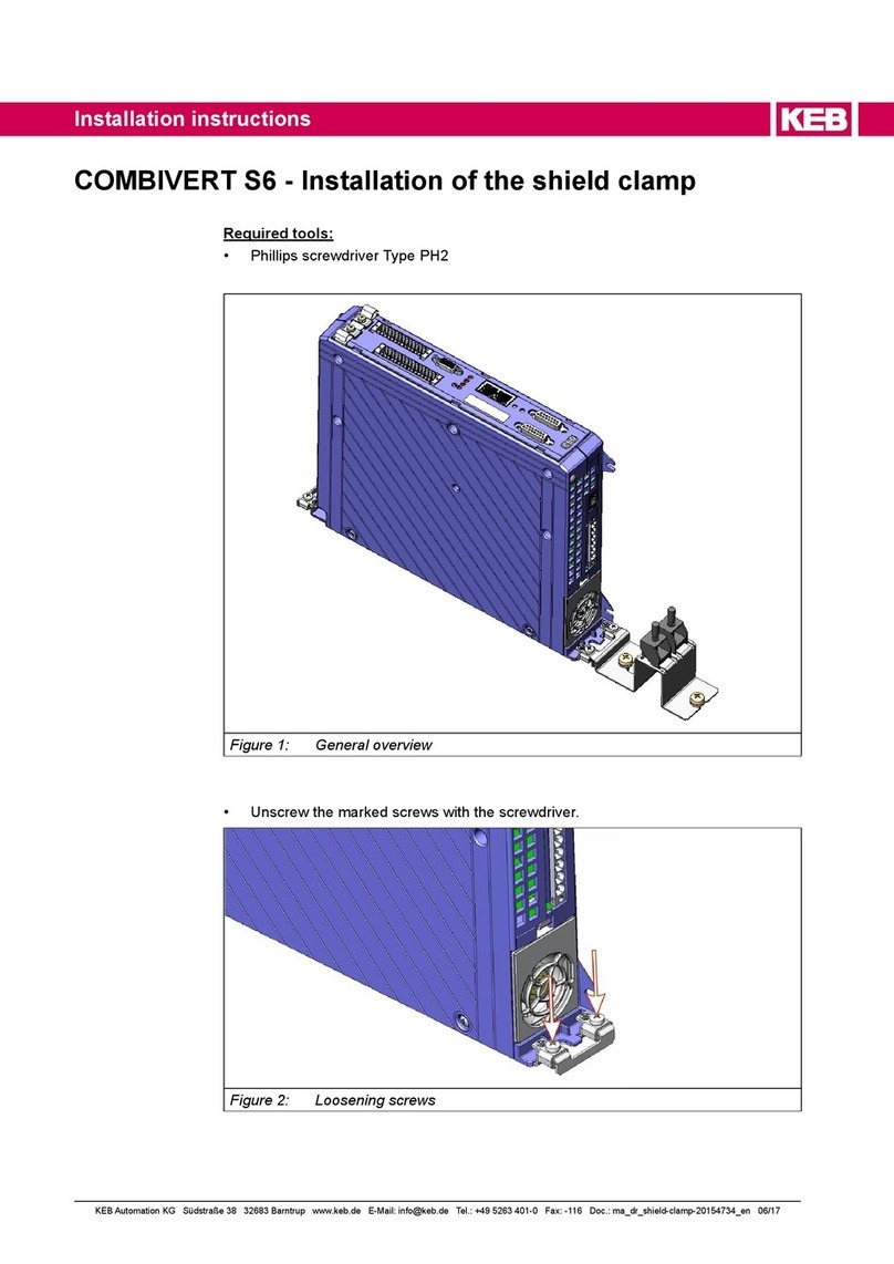
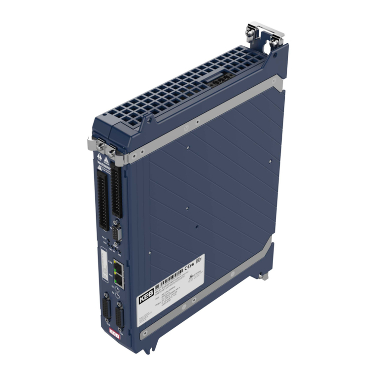
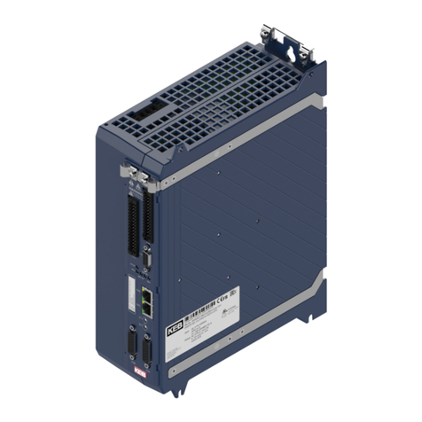
KEBCO COMBIVERT S6 Series User manual

Instructions for use
COMBIVERT S6
Installation Control PRO
Übersetzung der Originalanleitung
Dokument 20156056 EN 03

Impressum
KEB Automation KG
Südstraße 38, D-32683 Barntrup
Deutschland
Tel: +49 5263 401-0 • Fax: +49 5263 401-116
E-Mail: [email protected] • URL: https://www.keb.de
ma_dr_s6-cu-p-inst-20156056_en
Version 03 • Ausgabe 11/11/2022

Table of Contents
ma_dr_s6-cu-p-inst-20156056_en iii
Table of Contents
1 Introduction ................................................................................................................................................... 7
1.1 Markings................................................................................................................................................ 7
1.1.1 Warnings................................................................................................................................. 7
1.1.2 Information notes .................................................................................................................... 7
1.1.3 Symbols and markers ............................................................................................................. 8
1.2 Laws and guidelines.............................................................................................................................. 8
1.3 Warranty and liability............................................................................................................................. 8
1.4 Support.................................................................................................................................................. 8
1.5 Copyright............................................................................................................................................... 8
1.6 Validity of this manual ........................................................................................................................... 9
2 General Safety Instructions.......................................................................................................................... 10
2.1 Installation............................................................................................................................................. 10
2.2 Start-up and operation .......................................................................................................................... 11
2.3 Maintenance.......................................................................................................................................... 11
3 Product description ...................................................................................................................................... 12
3.1 Description of the control board PRO ................................................................................................... 12
3.2 Variants of the control board Pro .......................................................................................................... 12
3.3 Accessories........................................................................................................................................... 12
3.4 Connection and control elements.......................................................................................................... 14
3.5 Motor monitoring X1C (temperature, brake) ......................................................................................... 14
3.6 Control terminal strip X2A ..................................................................................................................... 15
3.7 Safety terminal block X2B..................................................................................................................... 15
3.8 Encoder interfaces X3A, X3B................................................................................................................ 15
3.9 Diagnostic interface X4A....................................................................................................................... 15
3.10 Fieldbus interface X4B.......................................................................................................................... 15
3.11 Fieldbus interface X4C.......................................................................................................................... 15
3.12 Rotary coding switch S1, S2 ................................................................................................................. 15
3.13 Status LEDs .......................................................................................................................................... 15
3.13.1 Boot display ............................................................................................................................ 15
3.13.2 VCC - LED .............................................................................................................................. 16
3.13.3 NET ST - LED......................................................................................................................... 16
3.13.4 DEV ST - LED......................................................................................................................... 16
3.13.5 OPT - LED .............................................................................................................................. 16
4 Connection of the control............................................................................................................................. 17
4.1 Assembly of wires ................................................................................................................................. 17
4.2 Terminal strip X2A................................................................................................................................. 18
4.2.1 Digital Inputs ........................................................................................................................... 18
4.2.2 Digital Outputs ........................................................................................................................ 19
4.2.3 Relay output;........................................................................................................................... 20
4.2.4 Analog input............................................................................................................................ 21
4.2.5 Analog output.......................................................................................................................... 22
4.2.6 Voltage supply ........................................................................................................................ 22
5 Safety module X2B........................................................................................................................................ 25
5.1 Safety manual type 5 ............................................................................................................................ 25

Table of Contents KEB Automation KG
iv ma_dr_s6-cu-p-inst-20156056_en
6 Diagnosis/visualisation X4A ........................................................................................................................ 26
6.1 Assignment of the terminal strip X4A.................................................................................................... 26
6.2 Data cable RS232 PC-Drive Controller................................................................................................. 26
6.3 USB-serial converter............................................................................................................................. 27
6.4 Connection of the RS485 interface ....................................................................................................... 27
7 Fieldbus interfaces........................................................................................................................................ 28
7.1 Type code fieldbus................................................................................................................................ 28
7.2 CAN....................................................................................................................................................... 28
7.3 Ethernet fieldbus interface .................................................................................................................... 29
7.3.1 EtherCAT ................................................................................................................................ 29
7.4 RS485 potential-free ............................................................................................................................. 31
8 Encoder interfaces ........................................................................................................................................ 33
8.1 Type code encoder interface................................................................................................................. 33
8.2 Multi-Encoder-Interface......................................................................................................................... 33
8.3 Input signals.......................................................................................................................................... 34
8.4 Encoder sockets X3A/X3B.................................................................................................................... 35
8.5 Encoder cable length ............................................................................................................................ 35
8.6 Description of the encoder interfaces.................................................................................................... 36
9 Brake control and temperature detection ................................................................................................... 38
9.1 Brake control......................................................................................................................................... 38
9.2 Temperature detection.......................................................................................................................... 39
9.2.1 Operation without temperature detection................................................................................ 40
9.2.2 Connection of a KTY sensor................................................................................................... 40
9.2.3 Connection of PTC, temperature switch or PT1000 ............................................................... 40
10 Revision History ............................................................................................................................................ 42
Glossary ......................................................................................................................................................... 43
Index ............................................................................................................................................................... 45

List of Figures
ma_dr_s6-cu-p-inst-20156056_en 5
List of Figures
Abb. 1 Pin assignment socket D-Sub-9 (top view) ............................................................................................ 26
Abb. 2 Serial cable for the connection to a PC.................................................................................................. 26
Abb. 3 Connection CAN bus.............................................................................................................................. 28
Abb. 4 RJ45 socket front view ........................................................................................................................... 30
Abb. 5 RJ45 socket front view ........................................................................................................................... 32
Abb. 6 Assignment of the input signals (as difference signals) ......................................................................... 34
Abb. 7 Encoder cable length ............................................................................................................................. 36
Abb. 8 Connection of a brake ............................................................................................................................ 39

List of Tables KEB Automation KG
6 ma_dr_s6-cu-p-inst-20156056_en
List of Tables
Tab. 1 Connector sets ....................................................................................................................................... 13
Tab. 2 Overview Connection and control elements........................................................................................... 14
Tab. 3 LEDs at power on................................................................................................................................... 16
Tab. 4 Function VCC LED................................................................................................................................. 16
Tab. 5 Function NET ST - LED ......................................................................................................................... 16
Tab. 6 Function DEV ST - LED ......................................................................................................................... 16
Tab. 7 Function OPT - LED............................................................................................................................... 16
Tab. 8 Wire-end ferrules and stripping length ................................................................................................... 17
Tab. 9 Assignment of the terminal strip X2A ..................................................................................................... 18
Tab. 10 Calculation the current consumption...................................................................................................... 23
Tab. 11 Serial interfaces ..................................................................................................................................... 26
Tab. 12 Connecting cable ................................................................................................................................... 26
Tab. 13 PIN assignment RJ45 EtherCAT............................................................................................................ 30
Tab. 14 Function of the LEDs.............................................................................................................................. 30
Tab. 15 Error status list ....................................................................................................................................... 31
Tab. 16 PIN assignment RJ45 RS485 potential-free .......................................................................................... 32
Tab. 17 Assignment X3A and X3B...................................................................................................................... 35
Tab. 18 Encoder specifications ........................................................................................................................... 36
Tab. 19 Assignment of the terminal block X1C ................................................................................................... 38
Tab. 20 Connection examples ............................................................................................................................ 40

Introduction | 1
ma_dr_s6-cu-p-inst-20156056_en 7
1 Introduction
The described devices, accessories, hardware and/or software are products of
KEB Automation KG. The enclosed documents correspond to conditions valid at
printing. Misprint, mistakes and technical changes reserved.
1.1 Markings
1.1.1 Warnings
Certain operations can cause hazards during the installation, operation or there-
after. There are safety informations in the documentation in front of these opera-
tions.
Warnings contain signal words for the severity of the hazard, the type and/or
source of the hazard, the consequence of non-compliance and the measures to
avoid or reduce the hazard.
GEFAHR Type and/or source of the hazard.
Leads to death or serious bodily injury if not observed.
a) Measures to avoid the hazard.
b) Can be supplemented by an additional danger sign or pictogram.
WARNUNG Type and/or source of the hazard.
May cause death or serious injury if not observed.
a) Measures to avoid the hazard.
b) Can be supplemented by an additional danger sign or pictogram.
VORSICHT Type and/or source of the hazard.
May cause bodily injury if not observed.
a) Measures to avoid the hazard.
b) Can be supplemented by an additional danger sign or pictogram.
ACHTUNG Type and/or source of the hazard.
Can cause damage to property if not observed.
a) Measures to avoid the hazard.
b) Can be supplemented by an additional danger sign or pictogram.
1.1.2 Information notes
Indicates to the user a special condition, prerequisite, scope or simplifica-
tion.
This is a reference to further documentation with barcode
for smartphones and link for online users.
https://www.keb.co.uk/nc/search

1 | Introduction KEB Automation KG
8 ma_dr_s6-cu-p-inst-20156056_en
Notes on conformity for use in the North American or Canadian mar-
ket.
1.1.3 Symbols and markers
üCondition
a) Action step
ðResult or intermediate result
Hyperlink
<Steuercode>
Lexicon entry
1.2 Laws and guidelines
KEB Automation KG confirms with the CE mark and the EU declaration of conform-
ity, that our device complies with the essential safety requirements.
The EU declaration of conformity can be downloaded on demand via our website.
1.3 Warranty and liability
The warranty and liability on design, material or workmanship for the acquired
device is given in the general conditions of sale.
Here you will find our general sales conditions.
https://www.keb.co.uk/terms-and-conditions
Further agreements or specifications require a written confirmation.
1.4 Support
Through multiple applications not every imaginable case has been taken into ac-
count. If you require further information or if problems occur which are not treated
detailed in the documentation, you can request the necessary information via the
local KEB Automation KG agency.
The use of our units in the target products is beyond of our control and
therefore exclusively the responsibility of the customer.
The information contained in the technical documentation, as well as any user-spe-
cific advice in spoken and written and through tests, are made to best of our know-
ledge and information about the intended use. However, they are considered for in-
formation only without responsibility and changes are expressly reserved, in partic-
ular due to technical changes. This also applies to any violation of industrial prop-
erty rights of a third-party.
Selection of our units in view of their suitability for the intended use must be done
generally by the user.
Tests can only be carried out within the scope of the intended end use of the
product (Application) by the Customer. They must be repeated, even if only
parts of hardware, software or the unit adjustment are modified.
1.5 Copyright
The customer may use the instructions for use as well as further documents or
parts from it for internal purposes. Copyrights are with KEB Automation KG and re-
main valid in its entirety.

Introduction | 1
ma_dr_s6-cu-p-inst-20156056_en 9
Other wordmarks and/or logos are trademarks (™) or registered trademarks (®) of
their respective owners.
1.6 Validity of this manual
This part of the instruction manual describes the implemented control card. It
• is only valid in conjunction with the instructions for use of the power part.
• contains only supplementary safety instructions.
• if certain functions or properties are version-dependent, this is indicated at the
appropriate place. The version number of the COMBIVERT can be found in
brackets after the material number.

2 | General Safety Instructions KEB Automation KG
10 ma_dr_s6-cu-p-inst-20156056_en
2 General Safety Instructions
The products are developed and built according to the state of the art and recog-
nized safety rules. Nevertheless, their use may create dangers to life and limb of
the user or third parties or damage to the machine and other material property.
The following safety instructions have been created by the manufacturer for the
area of electric drive technology. They can be supplemented by local, country- or
application-specific safety instructions. This list is not exhaustive. Non-observance
of the safety instructions by the customer, user or other third party leads to the loss
of all resulting claims against the manufacturer.
ACHTUNG Hazards and risks through ignorance!
a) Read the instructions for use.
b) Observe the safety and warning instructions.
c) Ask if something is unclear.
2.1 Installation
GEFAHR Electrical voltage at terminals and in the device!
Danger to life due to electric shock !
üFor any work on the device
a) Switch off the supply voltage.
b) Secure it against switching on.
c) Wait until all drives has been stopped in order that no regenerative energy can
be generated.
d) Await capacitor discharge time (min. 5 minutes). Measure DC voltage at the
terminals.
e) Never bridge upstream protective devices. Also not for test purposes.
ACHTUNG Use of unsuitable voltage sources!
Electric Shock!
a) Use for the connection only suitable voltage sources with safe isolation (SELV/
PELV) in accordance with VDE 0100 with nominal voltage of DC 24 V ±10 %.
b) Pay attention on a sufficient overvoltage category of the voltage supply.
c) With existing or newly wired circuits the person installing the units or machines
must ensure that the PELV requirements are met.
For a trouble-free and safe operation, please pay attention to the following instruc-
tions:
• The electrical installation shall be carried out in accordance with the relevant re-
quirements.
• Cable cross-sections and fuses must be dimensioned by the user according to
the specified minimum/maximum values for the application.
• For drive converters that are not isolated from the supply circuit (in accordance
with EN 61800-5-1) all control lines must be included in other protective meas-
ures (e.g. double insulation or shielded, earthed and insulated).
• When using components without isolated inputs/outputs, it is necessary that
equipotential bonding exists between the components to be connected (e.g. by
the equipotential line). Disregard can cause destruction of the components by
equalizing currents.

General Safety Instructions | 2
ma_dr_s6-cu-p-inst-20156056_en 11
2.2 Start-up and operation
The start-up (i.e. the starting of normal operation) is prohibited until the machinery
has been proved to conform to the provisions Directive 2006/42/EG and Directive
2014/30/EU; EN 60204-1 must be observed.
WARNUNG Wrong parameterization
Unintentional behaviour of the drive
üDuring initial start-up or replacement of the drive controller
a) Secure motors against automatic restart.
b) Check whether the appropriate parameter list for the application has been im-
ported.
WARNUNG Software protection functions as sole protection.
Protection function in case of software problems without function.
üSecuring a unit solely with software-supported functions is not sufficient.
a) Install external protective measures (e.g. limit switch) that are independent of
the drive controller.
2.3 Maintenance

3 | Product description KEB Automation KG
12 ma_dr_s6-cu-p-inst-20156056_en
3 Product description
3.1 Description of the control board PRO
Die Steuerkarte PRO stellt folgende Grundfunktionen zur Verfügung:
• Digital and analog inputs and outputs
• Serial diagnostic interface for connection to a PC
• Hardware of the control circuit „safety separated“ according to EN 61800-5-1
• Brake control, supply and feedback
• Motor protection by I²t, KTY, PT1000 or PTC input
• External supply of the control board
3.2 Variants of the control board Pro
Der 11-stellige Typenschlüssel zeigt die Varianten der Steuerkarte an. Nicht aufgeführte
Stellen sind für diese Anleitung ohne Bedeutung.
1. and 2. digit Device size
07…14 For motor power from 0.75…7.5 kW
3. and 4. digit Series
S6 COMBIVERT S6
5. digit Control type
P PRO
6. digit Variants
4 reserved
5 Safety module type 5
7. digit Housing
8. digit Connection, voltage, options
9. digit Control board variant
3 PRO | Multi-Encoder-Interface, CAN®, Ethernet-Fieldbus-Interface, RS485-po-
tential-free
4 PRO | no encoder interface, CAN®, Ethernet fieldbus interface, safe relay
5 PRO | Multi encoder interface, CAN®, Ethernet fieldbus interface, safe relay
E PRO | no encoder interface, CAN®, Ethernet fieldbus interface, safe relay, al-
ternative terminal strip
F PRO | Multi encoder interface, CAN®, Ethernet fieldbus interface, safe relay, al-
ternative terminal strip
10. digit reserved
11. digit reserved
3.3 Accessories
To be able to use preassembled cables provided by the customer, the connectors of the
control are optionally available. The following connector sets are available according to
the used options:

Product description | 3
ma_dr_s6-cu-p-inst-20156056_en 13
Housing/ phases/
control board
Set contains Material number
02 / 1ph / PRO terminal strip 28-pole
terminal strip 10-pole
terminal strip 8-pole
connector 3-pole
connector 6-pole
shielding bracket
2 x shielding clamp
00S6ZC0-0011
02 / 3ph / PRO 00S6ZC0-0009
04 / 3ph / PRO 00S6ZC0-0010
Tab.1: Connector sets

3 | Product description KEB Automation KG
14 ma_dr_s6-cu-p-inst-20156056_en
3.4 Connection and control elements
X1Z
X2A
PE
PE
X2B
X4A
X4B
X4C
S1
S2
X3AX3B
X1C Temperature monitoring, brake
control/ monitoring
X2A Control terminal block for digital in-
puts/outputs; 24V supply; relay out-
put;analog inputs and outputs;CAN
bus
X2B Safety module
X3A Encoder interface channel A
X3B Encoder interface channel B
X4A Diagnostic interface with
RS232/485 interface according to
DIN 66019II protocol; operator slot
X4B Fieldbus input / Port 0
X4C Fieldbus output / Port 1
S1 Rotary coding switch 1 (Low-Byte)
S2 Rotary coding switch 2 (High-Byte)
FS ST LED Safety state
VCC LED voltage supply (24V)
NET ST LED network / fieldbus status
DEV ST LED Inverter / device status
OPT optional
X1C
Tab.2: Overview Connection and control elements
3.5 Motor monitoring X1C (temperature, brake)
The terminal block X1C is a 10-pole, pluggable terminal block with spring-cage connec-
tion. It contains:
• 2 outputs for control of 24V motor brakes

Product description | 3
ma_dr_s6-cu-p-inst-20156056_en 15
• 2 control inputs for brakes or relays
• 1 analog input for temperature detection
3.6 Control terminal strip X2A
The control terminal strip X2A is a 28-pole pluggable, double-row terminal strip with
spring-cage connection. It contains:
• 8 digital inputs
• 2 digital outputs
• 1 Relay output
• 2 analog inputs (plus 1 switchable analog input)
• 1 analog output
• CAN bus interface
• 24V input and output
3.7 Safety terminal block X2B
The design of the terminal strip X2B depends on the safety module. The description is
given in a separate manual for the safety module.
3.8 Encoder interfaces X3A, X3B
Der COMBIVERT contains two universal encoder interfaces. The interfaces can be adap-
ted independently to different encoders.
3.9 Diagnostic interface X4A
The integrated RS232/485 interface serves for the connection of service tools (e.g. COM-
BIVIS) displays or the F6 operator. Telegram DIN 66019II is used as communication pro-
tocol.
3.10 Fieldbus interface X4B
The fieldbus interface X4B supports the following protocols:
• EtherCAT IN (fieldbus);
• Ethernet (fieldbus)
3.11 Fieldbus interface X4C
The fieldbus interface X4B supports the following protocols:
•EtherCAT OUT (field bus)
• Ethernet (fieldbus)
3.12 Rotary coding switch S1, S2
If the CAN protocol is active, the rotary coding switches S1 (low byte) and S2 (high byte)
define the node ID. If both switches are set to "0" or a faulty node ID is set, the node ID
from fb64 is active.
3.13 Status LEDs
3.13.1 Boot display
Before the LEDs start their normal function, they signal the boot procedure after switching
on:

3 | Product description KEB Automation KG
16 ma_dr_s6-cu-p-inst-20156056_en
LEDs Status Note
VCC
NET
DEV
OPT
ST
ST
off Device off
VCC
NET
DEV
OPT
ST
ST
Initialization Control is supplied with 24 V
VCC
NET
DEV
OPT
ST
ST
ready for operation Device is ready for operation and the LEDs start
with their normal function (approx. 3 s)
Tab.3: LEDs at power on
3.13.2 VCC - LED
VCC LED colour Description
off - Power supply of the control card switched off.
on green Control is supplied with 24 V.
Tab.4: Function VCC LED
3.13.3 NET ST - LED
NET ST LED colour Description
off - Device off or booting.
Blink
code
various depending on fieldbus => fieldbus interfaces.
Tab.5: Function NET ST - LED
3.13.4 DEV ST - LED
DEV ST LED colour Description
off - Device off or booting.
on red Error
on yellow No error, DC link not loaded.
on green no error, ready for operation.
flashing green No error, is used for identification of the unit (fb32).
Tab.6: Function DEV ST - LED
3.13.5 OPT - LED
OPT LED colour Description
- - reserved for options.
Tab.7: Function OPT - LED

Connection of the control | 4
ma_dr_s6-cu-p-inst-20156056_en 17
4 Connection of the control
Observe the following instructions to avoid malfunctions!
• Install control cables and power cables separately (approx. 10…20 cm distance);
Lay crossings in a right angle.
• In case of inductive load on the relay outputs a protective wiring must be
provided (e.g. free-wheeling diode).
• Electro magnetic interferences can be prevented by the following measures:
– Always use twisted and shielded cables for analog control lines. Connect
the shield at one side at the signal source.
– Twist digital control cables. Up from 3 m a shield may be required. In this
case connect the shield at both ends.
– Connect the shield of the brake and temperature monitoring together with
the motor shield. Leave the inner shields longer in order to avoid interfer-
ence coupling or decoupling (the latter during temperature measurement)
as far as possible.
The terminals of the control terminal block, enocder inputs and communication in-
terface are securely isolated in accordance with EN 61800-5-1.
4.1 Assembly of wires
ACHTUNG Loose and slack cable connections!
Malfunctions due to loose contacts.
a) Observe metal sleeve length and stripping length according to table.
b) Use a suitable pressing tool.
c) Make sure that all wires are inserted into the wire-end sleeve.
d) After inserting the cable into the terminal, check that it is firmly seated.
Cross-section Wire-end ferrule Metal sleeve
length
Stripping length
0.5 mm² with plastic collars 10 mm 12 mm
0.75 mm² 12 mm 14 mm
1.0 mm² 12 mm 15 mm
1.5 mm² without plastic col-
lars
10 mm 10 mm
0.2…1.5 mm²
ein- oder
feindrähtig
without wire-end
ferrule
- 10…12 mm
Tab.8: Wire-end ferrules and stripping length

4 | Connection of the control KEB Automation KG
18 ma_dr_s6-cu-p-inst-20156056_en
4.2 Terminal strip X2A
1
2
3
4
5
6
7
8
9
10
11
12
13
14
15
16
17
18
19
20
21
22
23
24
25
26
27
28
PIN Name Description
1 DI1 / AN3 Digital input 1 / analog input 3 (switchable via software)
2 DI2 Digital input 2
3 DI3 Digital input 3
4 DI4 Digital input 4
5 DI5 Digital input 5
6 DI6 Digital input 6
7 DI7 Digital input 7 (fast input => see programming manual)
8 DI8 Digital input 8 (fast input => see programming manual)
9 0V Reference potential for digital output
10 DO1 Digital output 1
11 0V Reference potential for digital output
12 DO2 Digital output 2
13 RLB reserved
14 RLA Relay output / NO contact
15 RLC Relay output/ switching contact
16 24Vout DC voltage output 24V (max. 100 mA together with terminal 26) for control the inputs (SELV).
17 AN1- non-isolated difference input 1
18 AN1+ Non-isolated difference input 1
19 AN2- non-isolated difference input 2
20 AN2+ Non-isolated difference input 2
21 0V Reference potential for analog inputs and outputs
22 ANOUT Analog output DC 0…10 V
23 CAN low CAN bus ISO High Speed according to ISO/DIN 11896 => fieldbus interfaces
24 CAN high CAN bus ISO High Speed according to ISO/DIN 11896 => fieldbus interfaces
25 CAN GND CAN ground isolated => fieldbus interfaces
26 24Vout DC voltage output 24V (max. 100 mA together with terminal 16) for control the inputs (SELV).
27 0V Reference potential for P24Vin at external supply
28 P24Vin Voltage output DC 24V for supply the control board and the brake
Tab.9: Assignment of the terminal strip X2A
4.2.1 Digital Inputs
Specification Number 8
Name DI1…DI8

Connection of the control | 4
ma_dr_s6-cu-p-inst-20156056_en 19
Terminals X2A.1…X2A.8
Classification Type 3 in accordance with DIN EN 61131-2
Low level (logical 0) -3 … +5 V / 3 mA
High level (logical 1) 11 … 30 V / 2 … 6 mA
Special features DI1 is switchable via software as analog input
AN3.
Connection Internal voltage supply External voltage supply
4 6 8
3
2
1 5 7 16
4 6 8
3
2
1 5 7 9
+
4.2.2 Digital Outputs
Specification Number 4 (2 at X2A and 2 at X2B)
Name DO1 … DO4
Terminals X2A.10, X2A.12
Type 24 V high-side switch
Classification DIN EN 61131-2
Output voltage Minimum P24Vin – 3 V
maximum P24Vin
Output current Maximum 100 mA per output (short-circuit proof)
Special features only ohmic load; no internal free-wheeling path

4 | Connection of the control KEB Automation KG
20 ma_dr_s6-cu-p-inst-20156056_en
Connection Connection appliance Connection external control
11
12
9
10
119
10 12
COMDI1DI2
ext.
4.2.3 Relay output;
4.2.3.1 Relay output 2-pole
Specification safe relay 2-pole
with positive-driven contacts Number 1
Name R1
Terminals X2A.14; X2A.15
Type 2-pole, NO contact
Switching voltage (rated) DC 24 V
Current 0.01…1 A
Switching frequency 0.1 Hz
Switching cycles 10,000,000 mechanical
500.000 at 30 V / 1 A
Delay time Switch on (close) maximum 50 ms
switch off (open) maximum 50 ms
Special features Only ohmic load; no internal free-wheeling path;
control only via safety module
WARNUNG No internal protection of the relay contacts!
Welding of the relay contacts due to inadmissible overload!
a) Limit the current by the normally open contact to 2 A (e.g. by using a fuse type
2A gG).
b) Observe further instructions in the safety manual.
Other manuals for COMBIVERT S6 Series
8
Table of contents
Other KEBCO Servo Drive manuals
Popular Servo Drive manuals by other brands

Hiwin
Hiwin D1-N Series user manual

LS ELECTRIC
LS ELECTRIC iX7NH Series quick start guide

National Instruments
National Instruments AKD EtherCAT Getting started

Stober
Stober POSIDRIVE FDS 5000 series Projecting manual

YASKAWA
YASKAWA Sigma-V Series user manual

Technosoft
Technosoft iPOS4803P Technical reference

Omron
Omron SMARTSTEP R7M-A Series user manual

Rockwell Automation
Rockwell Automation Allen-Bradley Kinetix TLP Series installation instructions

Lenze
Lenze L-force 9400 Hardware manual

Mitsubishi Electric
Mitsubishi Electric MDS-D-SPJ3 Specification manual

Danfoss
Danfoss 176F6489 installation instructions

ABB
ABB MicroFlex e190 Quick installation guide