PREREQUISITES
BUILDING NOTICE
When you install a stove and erect a chimney, you
may have to give building notice to the local Planning
and Building Committee. Contact the Planning and
Building Committee in your municipality for up-to-
date information.
DISTANCE TO FLAMMABLE STRUCTURAL
UNITS
Before deciding where to place the stove, you must
localise the beams in the ceiling and the roof in order
to determine whether it is feasible to install a chimney
in the desired place.
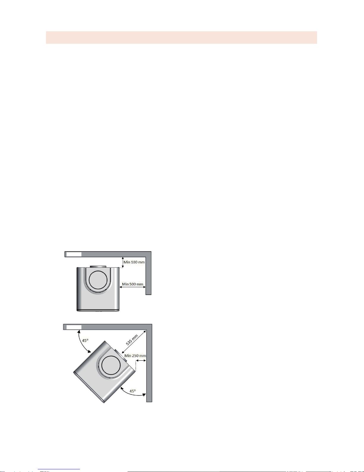
The K800 must be placed at a distance of 100 mm
from ammable walls.
The distance from the side of the stove to a per-
pendicular wall must be at least 500 mm ventilated
space. (See the illustration below).
For corner placement, the minimum distance to am-
mable walls is 250 mm. This is measured at an angle
of 45 degrees from the rear corners of the stove.
(See the illustration below).
The stove may be placed closer than the dimensions
given above, if the wall is not ammable, however,
not closer than 50 mm.
LOAD-BEARING SURFACE
Check that the oor joists have sucient load-bearing
capacity. The stove and the chimney can normally be
placed on an ordinary timber joist oor, if their total
weight does not exceed 400 kg.
FLOOR PLATE
A oor plate must be set in place to protect the oor
from ying embers. The oor plate must extend at
least 300 mm in front of the door. The width of the
oor plate must be at least the width of the stove plus
100 mm on each side. An example of an approved
oor plate is given on page 5.The oor plate can con-
sist of natural stone, concrete, clinker tiles or 0.7-mm
steel plate.
Naturally, you can use Keddy's own oor plate or
oor glass. These are installed after completing the
installation of the stove.
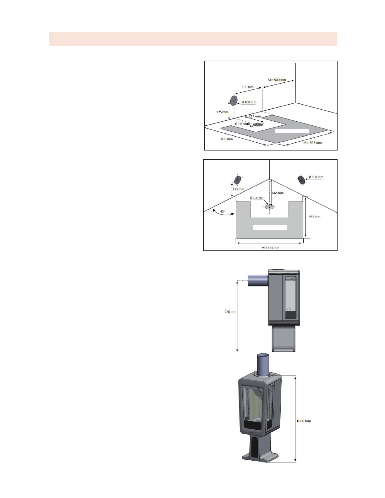
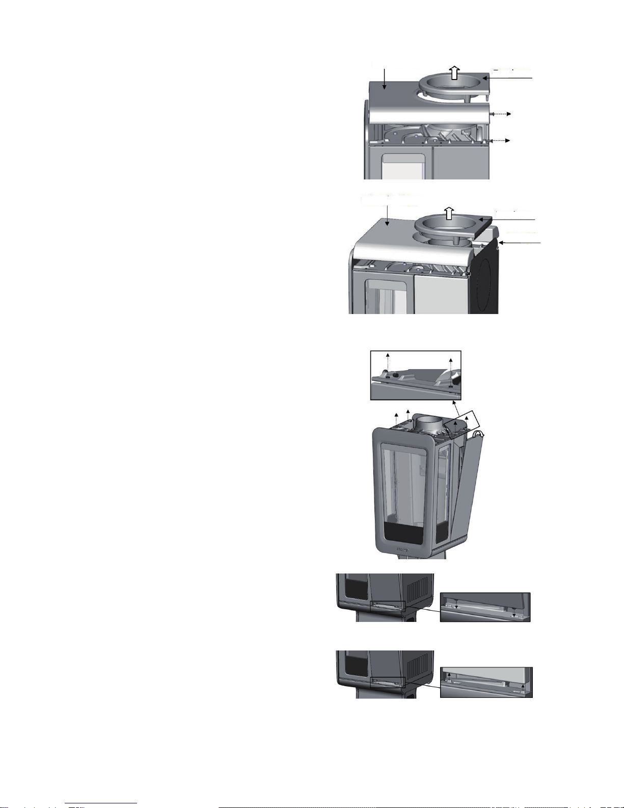
OUTDOOR AIR SUPPLY
The combustion of wood requires air/supply air. The
K800 can be provided with an external air supply,
which is recommended for properties with mechani-
cal ventilation, see also under the heading "Good to
know" on page 13.A sheet metal drum is used for
drawing an outdoor air duct. The connection diam-
eter of the supply air hose to the stove is 100 mm. If
the duct is more than 3 m long, the diameter of the
sheet metal drum must be increased to 125 mm. The
drum can be connected from below or from the rear,
see the illustration on page 5. (A stove's maximum
need for combustion air is approx. 20 m3/h).
The supply air must not be taken from crawl spaces.
If there is a crawl space, the sheet metal drum must
be extended to a valve in the foundation wall. If the
space is heated, the supply air channel must be insu-
lated against condensation.
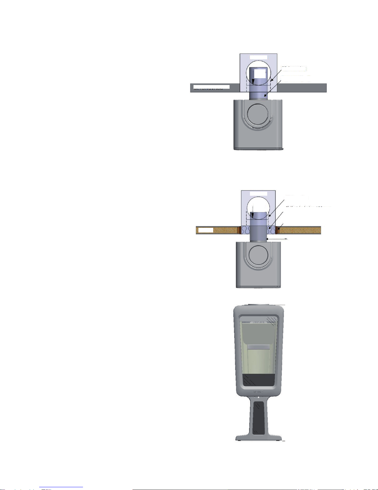
FLUE
The K800 must be connected to a ue approved
for at least 350ºC. As the area, length and material
of the ue are of great importance for the draught
formed in the ue, it is important the ue is not under-
dimensioned.The minimum recommended chimney
length is 3500 mm, measured from the top of the
stove, and the suitable area is 150 - 200 cm2 (approx.
150 mm in diameter.
Naturally, the K800 can also be connected to chim-
neys made of prefabricated elements, e.g. the Heda
Chimney.
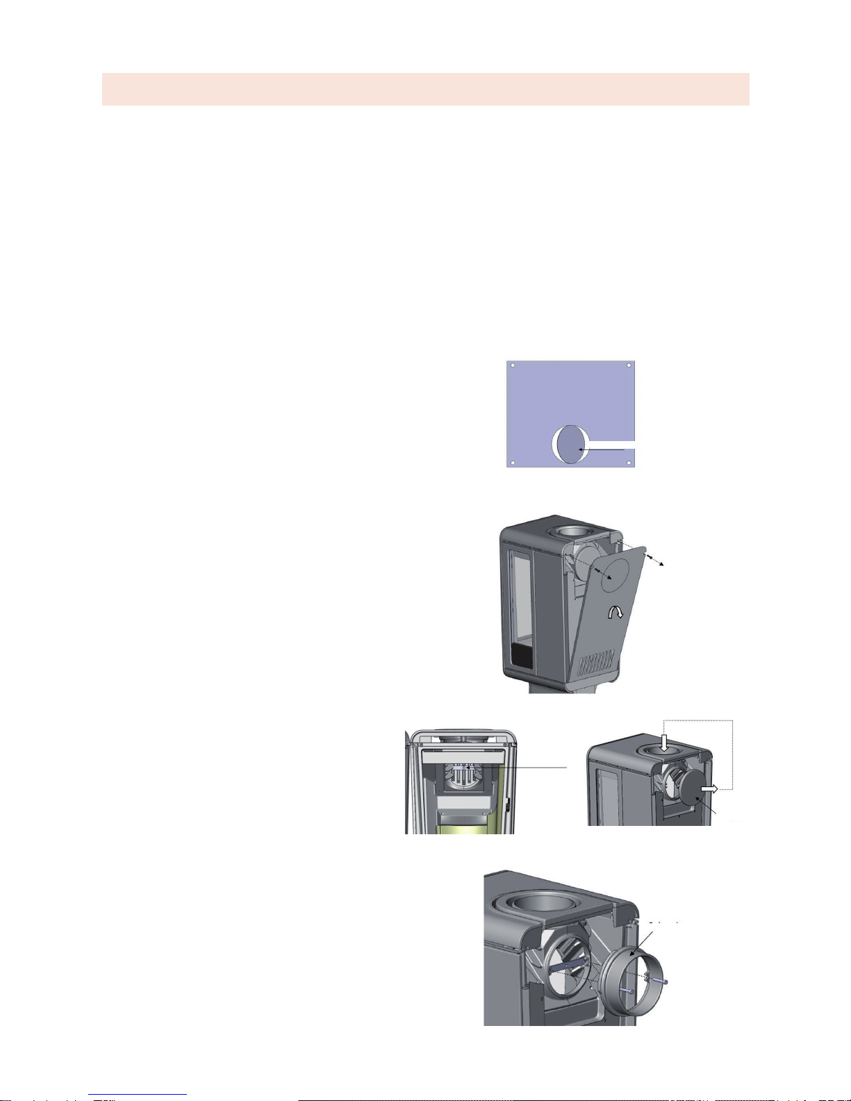
CHIMNEY CONNECTIONS
The illustration on page 5 shows the K800 from
above as well as where the ue ends up in relation
to the wall, depending on the choice of placement.
There is an illustration on page 6 for connection to an
existing ue.
Read the chimney's installation instructions before
starting on the preparations for the chimney and its
connection.
- 4 -
WALL
WALL