KEETEC RIDER MANUAL
EN
WARNING: PLEASE BE CAREFUL BEFORE
INSTALLATION AND READ THE INSTRUCTIONS
AND RECOMMENDATIONS GIVEN IN THIS
MANUAL. THE DEVICE MUST BE INSTALLED AND USED IN
ACCORDANCE WITH THIS GUIDE. THE DEVICE IS INTENDED
FOR INSTALLATION IN ALL MOTOR VEHICLES WITH 12/24V
ELECTRICAL NETWORK. THE DEVICE MUST BE CONNECTED TO
12/24V AND GROUNDED WITH NEGATIVE POLE. NEITHER
THE MANUFACTURER NOR THE SELLER ARE RESPONSIBLE FOR
ANY DAMAGES RESULTING FROM IMPROPER INSTALLATION,
USE OR OPERATION IN A DIFFERENT WAY THAN WRITTEN IN
THIS MANUAL. UNPROFESSIONAL INTERVENTION IN THE
DEVICE OR ITS MODIFICATION BRINGS THE RISK OF DAMAGE
TO THE DEVICE ITSELF, OR THE ELECTRICAL NETWORK OF THE
CAR AND LOSS OF WARRANTY. FOR CORRECT AND ERROR-
FREE OPERATION OF THE PRODUCT, WE RECOMMEND TO GET
THE INSTALLATION DONE BY A PROFESSIONAL INSTALLER.
I. SYSTEM DESCRIPTION
Keetec RIDER is an immobilizer intended for blocking the start/stop
button or other circuits in vehicles with 12/24V supply voltage. It serves
to prevent the use of the vehicle by an unauthorized person. User
authorization is made contactlessly using the RC SMART 2 controller,
which is automatically recognized in the system coverage zone. Part
of the system is the owner’s card with PIN code used for emergency
deactivation and entry into the service mode.
ATTENTION: The PIN code from the owner’s card cannot be
changed or issued a duplicate, so we recommend keeping
the card in a safe place.
II. SYSTEM INSTALLATION
Remove the plastic covers from the vehicle dashboard. Find the wires to
which the immobilizer shall be connected. Only use a digital multimeter
to verify the function of the wires in the vehicle, even if you are sure you
know the function of the wire. After determining the wires, disconnect the
battery and connect the immobilizer wiring harness to the wires neces-
sary for proper functionality, according to the attached wiring diagram.
Solder and insulate all connections. After completing the installation of
the immobilizer, connect the battery from the vehicle and insert the fuse
into the fuse box of the immobilizer. Test the correct functionality of the
system and the vehicle. Return the plastic dashboard covers to their place.
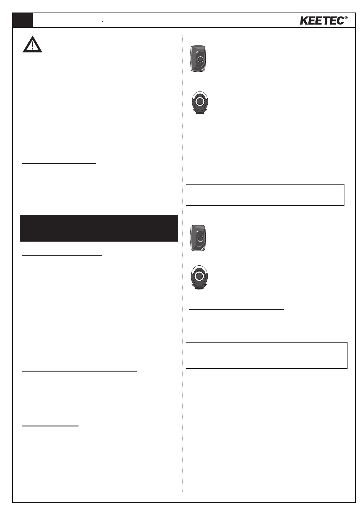
LOCATION OF THE CONTROL UNIT AND SERVICE BUTTON
The control unit should be placed in a hidden and hard-to-reach place,
for example in the original wiring of the vehicle. Place the service button
in an accessible place.
III. AUTHORIZATION OF THE OWNER
• Authorization by the RC SMART 2 remote control is automatic
based on the presence of the remote control in the vehicle.
• Emergency authorization using the service button in the
absence of the remote control. (See Chapter V. - EMERGENCY
DEACTIVATION).
IV. SERVICE MODE
The service mode can be activated with the service button or the remote
control.
CONDITION: To activate the service mode, at least one of the conditions
for a valid authorization must be met:
1. Remote control is present in the vehicle.
2. System was authorized in an emergency by entering the PIN code
from the owner’s card (see chapter V. - EMERGENCY DEACTIVATION).
Activation of service mode by remote control
Turn on the ignition or start the vehicle, press and hold the
button on the remote until the LED on the remote goes out. The
activation of the service mode is announced by the buzzer
beeping 5 times.
Activation of service mode with service button
PIN code entry procedure:
• Press and hold the service button until the LED indicator
lights up (approx. 2 seconds).
• Release the button.
• Press the service button as many times as the value of the first
digit of the PIN code, the LED indicator will flash 3 times.
• Press the service button as many times as the value of the second
digit of the PIN code, the LED indicator will flash 3 times
• Press the service button as many times as the value of the third digit of
the PIN code, the LED indicator will flash 3 times
• Press the service button as many times as the value of the fourth digit
of the PIN code, the LED indicator will flash 3 times
• The activation of the service mode is announced by the buzzer beeping
5 times. The PIN code is indicated on the owner’s card.
The active service mode is signaled by the permanently lit
service button LED while the ignition is on.
Deactivation of service mode by remote control
Turn on the ignition or start the vehicle, press and hold the
button on the remote until the LED on the remote goes out. The
deactivation of the service mode is announced by the buzzer
beeping 5 times.
Deactivation of service mode with service button
Enter the service PIN code using the service button in the same
way as for activation. Deactivation of the service mode is
announced by 5 beeps of the buzzer.
V. EMERGENCY DEACTIVATION
Emergency deactivation is used for one-time authorization of the driver
in the event the absence of the remote control (loss of the remote control,
discharge of the battery in the remote control).
NOTICE: Validity of the emergency deactivation is limited to 1 minute.
For this reason, it is necessary to start the vehicle within one minute from
the successful emergency deactivation.
Deactivation procedure:
• Press and hold the service button until the LED indicator lights up
(approx. 2 seconds).
• Release the button.
• Press the service button as many times as the value of the first digit of
the PIN code, the LED indicator will flash 3 times.
• Press the service button as many times as the value of the second digit
of the PIN code, the LED indicator will flash 3 times.
• Press the service button as many times as the value of the third digit of
the PIN code, the LED indicator will flash 3 times.
• Press the service button as many times as the value of the fourth
digit of the PIN code, the LED indicator flashes 3 times, the system is
deactivated once and the buzzer beeps 2 times briefly.


