PRE-ASSEMBLY INSTRUCTIONS
PRE-ASSEMBLY INSTRUCTIONS.......................................................1
ASSEMBLY INSTRUCTIONS...............................................................4
X-BAR INSTALLATION.........................................................................6
FLYWHEEL GUARD INSTALLATION.................................................10
CHECKING FOR PROPER OPERATION............................................11
SAFETY INFORMATION AND INSTRUCTIONS.................................12
COMPUTER OVERVIEW....................................................................13
CALIBRATION INFORMATION...........................................................14
PREVENTITIVE MAINTENANCE CHART............................................15
WARRANTY TERMS .........................................................................16
BEFORE ASSEMBLING
Always follow the steps in this manual as you assemble your M3X. Do not skip, substitute or
modify any steps or procedures of this assembly, as doing so could result in personal injury and
will void your warranty. We have put a number of precautions in this manual.
WARNING: This symbol appearing throughout this manual means PAY ATTENTION! BE
ALERT! When you see this warning symbol, your safety is involved. It is being used to call
attention to POTENTIAL hazards that could result in personal injury or loss of life.
!
NOTE: Informs you about things we recommend you do or are aware of, before performing the
assembly. These notes are placed in the manual to aid you during a certain procedure or to
make you aware of any general mandatory actions or information.
!
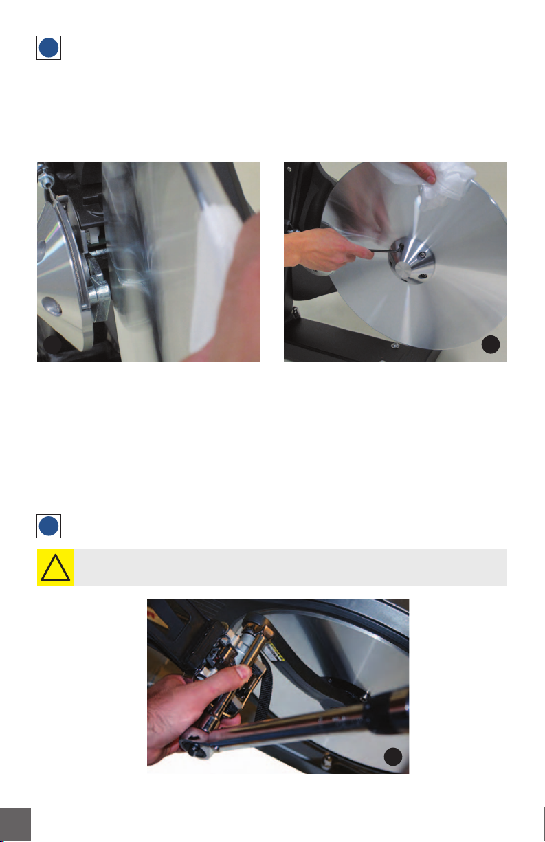
UNPACKING THE M3X
Carefully remove the M3X from the cardboard box. Lay-out all the components and check to
assure all parts are present and undamaged. If parts are missing or damaged, contact your local
dealer, distributor or Keiser Corporation Service Department. After unpacking and verifying parts,
you are ready to start your assembly. You need an area that is free of dirt, dust or other foreign
material that could impair the assembly of your M3X.
Torque wrench (Minimum 45 Nm / 35 ft-lb) 16mm, or 5/8” crowfoot
4” extension
13mm Combination Wrench
3mm Allen Wrench
15mm open-end wrench
4mm Allen Wrench
16mm, or 5/8” open-end wrench
#2 Phillips screwdriver
5mm Allen Wrench
6mm Allen Wrench
Paste or spray wax (used to clean after assembly)
Clean cloth
LPS #3 Heavy Duty Rust Inhibitor w/straw
Socket Wrench/Ratchet
15mm crowfoot
2 x 10mm Wrenches
10mm Socket
TOOLS YOU WILL NEED
NOTE: The substitution or modification of any part or component, other than what is approved
by Keiser, will void your warranty.
!
1


 Service manual")