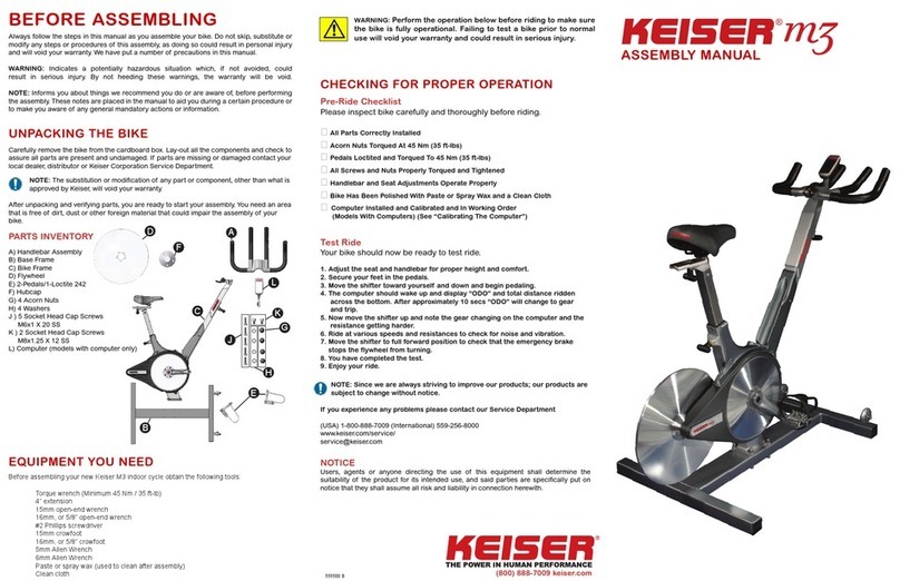
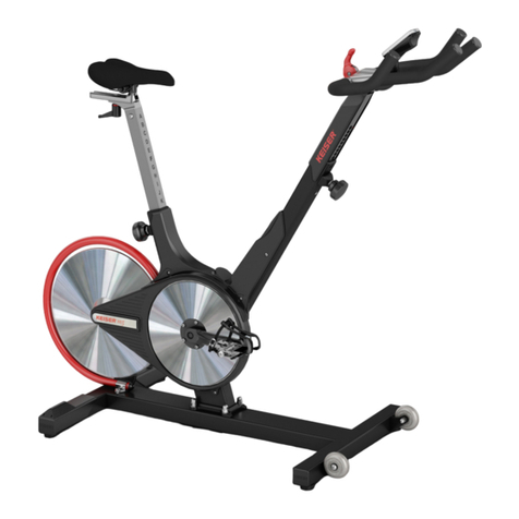
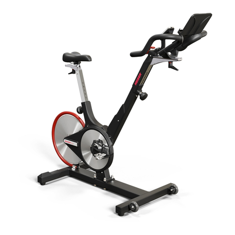
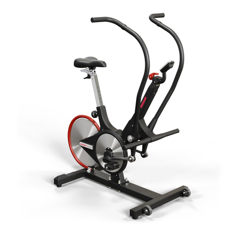
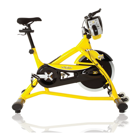
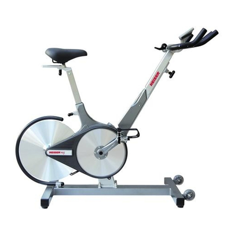
Keiser M3i lite User manual

M3i INDOOR GROUP CYCLE
M3i INDOOR CYCLE
INSTALLATION AND
OPERATION MANUAL

p02.
M3i INDOOR GROUP CYCLE
CONTENTS 03 — IMPORTANT SAFETY INSTRUCTIONS
04 — INTRODUCTION
04 — WEIGHT AND FOOTPRINT
04 — ASSEMBLY
04_TOOLS REQUIRED FOR ASSEMBLY
05_PARTS LIST
06_PRODUCT OVERVIEW
07_MOUNTING THE CYCLE TO THE BASE
07_INSTALLING THE FLYWHEEL AND HUBCAP
08_INSTALLING THE FLYWHEEL GUARD
09_INSTALLING THE PEDALS
10_INSTALLING THE COMPUTER
10_ASSEMBLING THE HANDLEBAR
12_ASSEMBLING THE DEVICE HOLDER
12_APPLY THE HOLE COVER DECALS
12_FINAL INSTALLATION AND CHECKING FOR PROPER
OPERATION
13_SETTING TRIP UNITS TO MILES OR KILOMETERS (KM) AND
BIKE ID NUMBER
14 — M3i SERIES COMPUTER
16 — SET UP AND OPERATION
16_EMERGENCY STOP
16_ADJUSTMENT KNOB INSTRUCTIONS FOR SEAT AND
HANDLEBAR HEIGHT
17_LEVELLER FOOT ADJUSTMENT
17_POSTURE AND BODY POSITION
18_SELECTING SEAT HEIGHT
18_PEDAL PLACEMENT
19_HANDLEBAR HEIGHT ADJUSTMENT
19_SETTING THE FORWARD AND BACKWARD SEAT POSITION
20_OPERATION OF THE CYCLE
21 — MAINTENANCE
21_PREVENTATIVE MAINTENANCE SCHEDULE
22 — COMPUTER BATTERY REPLACEMENT
22 — REGULATORY AND
COMPLIANCE NOTICES
23 — WARRANTY

p03.
M3i INDOOR GROUP CYCLE
1. Read these instructions.
2. Keep these instructions.
3. Heed all warnings.
4. Follow all instructions.
5. Only use replacement parts recommended by
Keiser Corporation.
6. Replace defective components immediately
and/or keep the equipment out of use until
repaired.
7. Routinely check and pay special attention to
components most susceptible to wear.
8. Maximum weight of the rider shall not exceed
300 lbs (136 kg).
9. The cycle is NOT designed with a freewheel,
but a fixed gear system. When the flywheel is in
motion, the pedals will also be in motion.
10. Never remove your feet from the pedals while
the flywheel is in motion as serious user injury
may occur.
11. Always secure the pedal clip strap by placing
your foot on the pedal and in the toe cage.
Locate the strap and pull up on it to tighten.
It should be snug but not too tight to cause
discomfort.
12. The emergency brake allows you to safely slow
or stop the motion of the flywheel. Move the
emergency brake away from you to increase
the gear and slow the motion of the flywheel.
Move the emergency brake all of the way
forward to engage the emergency stop.
13. This cycle is intended for use in training areas
of organizations such as sport associations,
educational establishments, hotels, clubs and
studios, where access and control is specifically
regulated by the owner (person who has the
legal responsibility).
14. Keep children and pets clear from the unit at
all times, especially while in use. Children shall
not play with the cycle. Cleaning and user
maintenance shall not be made by children
without supervision.
15. This cycle can be used by children aged from
14 years and above and persons with reduced
physical, sensory, or mental capabilities or lack
of experience and knowledge if they have been
given supervision or instruction concerning use
of the cycle in a safe way and understand the
hazards involved.
16. The cycle should be positioned on a stable,
level, horizontal surface.
17. There should be a clearance of no less than 24
inches (0.6 m) of free area on all sides of the
cycle. When cycles are positioned adjacent to
each other the free area may be shared.
18. Movements such as pedaling at high speeds
or pedaling while standing are considered
advanced techniques, and should only be
performed when the rider has reached an
advanced level.
19. Ensure that all adjustment handles that could
interfere with the user’s movement are not left
projecting as to come in contact with the rider
during operation.
20. Before dismounting, push the emergency
brake to the most forward position to engage
the emergency stop.
WARNING: This symbol appearing throughout this manual means PAY ATTENTION! BE ALERT! When
you see this warning symbol, your safety is involved. It is being used to call attention to POTENTIAL
hazards that could result in personal injury or loss of life.
IMPORTANT SAFETY INSTRUCTIONS
24 in
(0.6 m)
24 in
(0.6 m)
Training Area
Free Area
60.5 in
(1.54 m)
24 in
(0.6 m)
25.75 in
(0.65 m)
24 in
(0.6 m)

p04.
M3i INDOOR GROUP CYCLE
1. Carefully remove the cycle from the box.
2. Carefully unwrap the cycle.
3. Layout all the cycle components and compare them to the “Parts List” on page 5.
4. Check that all parts are present and undamaged.
NOTE: If parts are missing or damaged contact your local dealer, distributor or Keiser Corporation Service
Department.
Thank you for purchasing Keiser’s premier M3i indoor cycle. Your new resistance system is a revolutionary way to
exercise providing a smoother, quieter, and more predictable workout.
The following tools are required to assemble the cycle but not supplied:
WARNING: Use caution when using a box cutter or other tool with a sharp blade to unwrap the
cycle. A sharp tool can cause damage to the seat, handlebar, or scratch the frame of the cycle.
INTRODUCTION
WEIGHT AND FOOTPRINT
TOOLS REQUIRED FOR ASSEMBLY
Total Weight
Qty
1
1
1
1
1
1
2
Qty
1
1
1
1
1
1
Description
Torque wrench (Minimum 45 Nm/35 ft-lb)
4 inch extension
15 mm open-end wrench
16 mm, or 5/8 inch open-end wrench
#2 Phillips screwdriver
15 mm crow foot
10 mm wrenches
Description
16 mm, or 5/8 inch crowfoot
5 mm Allen wrench
6 mm Allen wrench
Paste or spray wax (used to clean after
assembly)
Clean cloth
LPS #3 heavy-duty rust inhibitor
with straw
91 lbs (41.27 kg)
Length 60.5 inches (1537 mm) x Width 25.75 in (654 mm)M3i Footprint
ASSEMBLY

p05.
M3i INDOOR GROUP CYCLE
PARTS LIST
QtyDescription Part Number
47/16-20 Acorn Nuts 555022
1Flywheel 555003
5M6 x 1 x 20, Socket Head Cap Screw 9502
1Sweat Guard Cover 555080
47/16 Washers 9384
1Handlebar 550844
2Flywheel Guard Bracket 555025
1M6 x 1, Hex Nut 9508
1Handlebar Slide 555026
1Hubcap 555005
1Loctite 242 - Thread Locking Compound 105550
1L-Handle Assembly 550828
1Computer 550853X
1Left and Right Pedals 540831
1M6 x 1 x 45, Hex Head Screw 9525
1Handlebar Spacer 555031
1Device Holder 555085
1Base 550814
1
9
5
13
17
2
10
6
14
18
3
11
7
15
19
4
12
8
16
1
9
5
13
17
2
10
6
14
18
3
11715 19
4
12
8
16
20
1Cycle - Main Frame 550867
1Flywheel Guard 550845
20
5Hole Cover Decal 555379
21
21

p06.
M3i INDOOR GROUP CYCLE
PRODUCT OVERVIEW
Seat
Resistance Lever/Emergency Brake
Flywheel
Shimano™ Combo Pedals
Forward/Backward Seat Adjustment Handle
Neutral Position Handlebar
Levelling Foot
Transport Wheels
Up/Down Seat Adjustment Knob
Forward/Backward Handlebar Adjustment Handle
Device Holder
Flywheel Guard
Up/Down Handlebar Adjustment KnobBelt Cover
Water Bottle Holder
110
514
211
615
312
716
413
9
Computer System with Bluetooth®smart
17
5
2
6
3
8
4
9
1
10
13
11
14
16
12
17
15
7
Base
8

p07.
M3i INDOOR GROUP CYCLE
NOTE: Due to the weight of the cycle, it is recommended that two
people perform this part of the assembly.
1. Align the holes of the cycle with the studs of the base,
refer to Figure 1. The front of the cycle should face the
wheels of the base.
2. Place the cycle onto the base.
3. Insert a washer (supplied) on each of the four studs.
4. Install an acorn nut (supplied) on each stud and then
hand tighten the acorn nuts.
5. Torque the acorn nuts to 45 Nm (35 ft-lbs) using a 16 mm
or 5/8” crowfoot attached to a torque wrench.
1. Place the shifter lever in the downward position, refer
to Figure 2.
2. Slide the ywheel between the two magnets and over
the hub, refer to Figure 3.
MOUNTING THE CYCLE TO THE BASE
INSTALLING THE FLYWHEEL AND HUBCAP
WARNING: Failure to follow these instructions may cause damage to the ywheel.
Figure 1. Cycle and Base Alignment
Figure 3. Location of MagnetsFigure 2. Shifter Lever Position

p08.
M3i INDOOR GROUP CYCLE
1. Remove the two Allen screws and washers from the base
frame, refer to Figure 5. Do not discard the screws. They
will be used to mount the ywheel guard.
2. Place the open end of the ywheel guard over the
mounting stud located on the frame of the cycle, refer to
Figure 6.
3. Swing the guard over the ywheel, refer to Figure 7.
INSTALLING THE FLYWHEEL GUARD
Figure 4. Flywheel and Hubcap Installation
Figure 5. Remove the Allen Screws
Figure 6. Flywheel Guard Placement Figure 7. Center Flywheel Guard Over Flywheel
NOTE: When installing and centering the guard, try to avoid touching the ywheel with the guard.
3. Align the holes of the ywheel with the holes of the hub.
NOTE: The ywheel should be ush against the hub.
4. Install the hubcap:
a) Align the holes of the hubcap with the holes of the
ywheel, refer to Figure 4.
b) Hold the ywheel in position.
c) Use the ve, M6x1x20 SS socket head cap screws
(supplied) and a 5 mm Allen wrench and tighten
the screws.
d) Be sure the ywheel is ush against the face of the
hub. Spin the ywheel to make sure the it runs true
and straight (no wobbling).

p09.
M3i INDOOR GROUP CYCLE
4. Attach the brackets on the end of the ywheel guard, refer
to Figure 8. Use the M6 x 1 x 45 hex head screw and nut
(supplied). Hand tighten the screw and nut.
5. Tighten the brackets to the base frame with the two Allen
screws and washers removed in step 1. Do not fully
tighten the bolts.
6. Check to ensure that there is enough clearance between
the ywheel and the ywheel guard.
7. Using 2, 10 mm wrenches and a 5 mm Allen wrench,
tighten the bolt and screws to secure the ywheel guard
centered with the ywheel.
1. Unwrap the pedals and the Loctite 242 - thread locking
compound.
2. Clean the threads of the pedals with a clean cloth.
3. Apply thread locking compound to the pedal threads.
4. Use a 15 mm open-end wrench and install the pedals:
Left Pedal - Thread the left pedal (marked L) into the
left side of the left crank arm by turning it counter-
clockwise, refer to Figure 9.
Right Pedal - Thread the right pedal (marked R) into the
right side of the right crank arm by turning it clockwise,
refer to Figure 10.
5. Tighten the pedals with a torque wrench, 4 inch
extension, and 15 mm crowfoot. Torque the pedals to
45 Nm (35 ft-lbs).
6. Apply LPS#3 to the left bottom bracket bearing.
7. Apply LPS #3 to the clip-in portion of the pedals.
INSTALLING THE PEDALS
Torque: 45 Nm
(35 ft-lbs)
Torque: 45 Nm
(35 ft-lbs)
WARNING: Failing to install the pedals with a thread locking compound, or crossing the threads will
damage them, and could result in serious injury to the user.
Figure 8. Align, Attach, and Tighten Flywheel
Guard Brackets
Figure 10. Installing the Right Pedal, Turn ClockwiseFigure 9. Installing the Left Pedal, Turn Counter-
Clockwise
NOTE: A torque wrench with 4 inch extension and 15 mm crowfoot are required to correctly torque the pedals.
Left Bottom
Bracket
Bearing

p10.
M3i INDOOR GROUP CYCLE
1. Use a #2 Phillips screwdriver and remove the computer
mounting screw from the handlebar tube, refer to
Figure 11.
2. Coil the computer cable into the computer mount
cavity, refer to Figure 12.
3. Slide the computer up into the two locking ears.
4. Insert and secure the computer with the screw
previously removed using a #2 Phillips screwdriver.
1. Remove screws from both sides of the sweat guard,
refer to Figure 13.
2. Slide on the guard cover over the sweat guard and
snap it in place, refer to Figure 14.
3. Secure the cover with the screws previously removed.
Do not over tighten screws.
4. Remove the four 8 mm Allen screws from the handlebar
tube, located below the computer mount, refer to
Figure 15.
INSTALLING THE COMPUTER
ASSEMBLING THE HANDLEBAR
Figure 11. Remove Mounting Screw From Handlebar
Tube
Figure 13. Remove Screws From Sweat Guard Figure 14. Align the Guard Cover Over the Mounting
Holes
Figure 12. Attach the Computer to the Handlebar Tube

p11.
M3i INDOOR GROUP CYCLE
5. Attach the handlebar slide to the handlebar tube with
the four 8 mm screws previously removed. Use a 6
mm Allen wrench to tighten screws. There should be
no gap between the handlebar slide and the handlebar
tube, refer to Figure 16.
6. Install the handlebar on the handlebar slide:
a) Disassemble the L-handle assembly. Use a 5 mm
Allen wrench and remove the screw and washer to
remove the handle stud.
b) Fit the L-handle stud in the handlebar spacer, and
then attach the handlebar to the handlebar slide, refer
to Figure 17. Hand tighten the assembly.
c) Place the L-handle onto the handle stud. The
L-handle should point away from the cycle when the
handlebar is tight. Install the screw and washer to
secure the assembly, refer to Figure 18.
7. Loosen the L-handle. Slide the handlebar back and
forth, making sure it can move freely on the handlebar
slide.
Figure 15. Remove the 8 mm Screws From the
Handlebar
Figure 17. Assemble Handlebar, Handle Stud, and
the Handlebar Spacer
Figure 16. Attach the Bottom Slide to the Handlebar
Tube
Figure 18. Install L-Handle and Secure with Screw
and Washer
Disassemble the L-Handle
Be sure to install the handlebar spacer with
the tall section towards the back of the cycle.

p12.
M3i INDOOR GROUP CYCLE
ASSEMBLING THE DEVICE HOLDER
Figure 19. Assemble the device holder to the
handlebar
Figure 20. The assembled handlebar and
device holder
To install the device holder, apply force in the direction shown in Figure 19. The device holder will t to the handlebars as
shown in Figure 20.
FINAL INSTALLATION AND CHECKING FOR PROPER OPERATION
• Are all parts correctly installed?
• Are the four Acorn nuts that secure the main cycle frame
to the base frame torqued at 45 Nm (35 ft-lbs)?
• Are pedals installed with thread locking compound and
torqued to 45 Nm (35 ft-lbs)?
• Are all screws and nuts properly torqued and tightened?
• Do the handlebar and seat adjustments operate
properly?
• Was LPS #3 applied to the left bottom bracket bearing?
• Was LPS #3 applied to the clip-in portion of the pedals?
• Is the computer installed and operational?
• Polish the cycle with paste or spray wax and a clean
cloth?
• If all assembly requirements have been met, test ride
the cycle.
NOTE: Perform the operations below before riding the cycle. Failing to test a cycle prior to normal use will void your
warranty and could result in serious injury.
APPLY THE HOLE COVER DECALS
Figure 21. Hole Cover Decal Placement
Install the hub cover decals as shown in gure 21.
The decals should completely cover each of the 5
holes on the ywheel hubcap.

p13.
M3i INDOOR GROUP CYCLE
1X
1X
NOTE: STEPS 1 THROUGH 7 MUST BE COMPLETED WITHIN 1 MINUTE
SETTING TRIP UNITS TO MILES OR KILOMETERS (KM) AND BIKE ID NUMBER
(Unless otherwise specied or requested at the time of purchase, the M3i trip distance is set to miles.)
1X
Begin with the bike off, push shift lever
all the way down
Pedal 1 full revolution. The bike id
(bid) in the screen above is 0, yours
may be different. Also, notice the 1
in the “TIME ROW”.
Pedal 1 full revolution. Notice the 2
in the “TIME ROW”.
Pedal 1 full revolution. Notice the 3
in the “TIME ROW”.
Move the shift lever from stop to
stop 6 times.
bike id number (bid)
USA = the trip units
were successfully set
to Miles
EURO = the trip units
were successfully set
to Kilometers
12 3
45 6
78 9
Conrm the correct units have been
set.
Gear 8 to 16
holds bid number
Gear 1 to 7
decreases bid
number
Gear 17 to 24
increases bid
number
TIME ROW
TIME ROW TIME ROW
Set shift lever to gear 21 for Miles, or
set shift lever to gear 19 for Kilometers.
Set shift lever to gear 19 for Miles, or
set shift lever to gear 21 for Kilometers.
Once the trip units have been set, you
have the opportunity to adjust the
bike id number. Adjust the shift lever
to attain the desired bike id number,
then set the shift lever to any number
between gear 8 and 16.
NOTE: The computer will only shut
down while the shift lever is be-
tween gears 8 and 16.

p14.
M3i INDOOR GROUP CYCLE
LINE 1 - BACKLIGHT SENSOR
While the M3i series computer is awake, the backlight sensor automatically detects ambient light levels in the room and
turns on the backlight display when needed.
LINE 2 - RPM (CADENCE)
The RPM displays the cyclists revolutions per minute of the crank arm. RPM is also known in the cycling world as cadence
and is roughly the speed at which the cyclist is pedaling.
LINE 3 - POWER AND ENERGY
The power output is displayed in Watts (currently generating) and Kilocalories (total value for the workout). The computer
toggles back and forth between Watts for 8 seconds and Kilocalories for 2 seconds. The rated accuracy for power be-
tween 30 and 160 rpm is ±5 Watts for Power below 50 Watts, and ±10% for power above 50 Watts.
LINE 4 - HEART RATE
If there is no Heart Rate signal, a steady heart symbol and a zero will be displayed. If a participant is wearing a Heart Rate
strap, once the computer locks onto the signal, the heart symbol will blink and display the heart rate. Please note that the
Heart Rate strap must be Polar compatible and coded.
LINE 5 - ELAPSED TIME
The number shown reports the total time spent cycling and will reset to zero after 60 seconds of inactivity or if the com-
puter is reset using the gear shifter.
LINE 6 - GEAR
Gears from 1 to 24 are displayed on the bottom left hand of the screen.
LINE 7 - ODOMETER/TRIP DISTANCE
For the rst 8 seconds when the computer is activated, the odometer will display the total distance the cycle has been
ridden. This feature is for service and maintenance purposes only. After 8 seconds, the odometer will disappear, the trip
units will display “USA” for trip distance set to Miles, or “EURO” for trip distance set to Kilometers. As soon as the units
disappear, trip will display for the remainder of the workout. Note, to change the trip units, see instructions for setting bike
id and trip units to miles/kilometers.
AVERAGE CALCULATIONS
To view averages: RPM (Cadence), Power, and Heart Rate at any point in the workout, stop pedaling for three seconds.
This will ash your averages until you start pedaling again or until the computer goes to sleep after 60 seconds.
INTERVAL TRAINING
To initiate an interval, starting from a high gear drop the shifter handle to gear 1 for 1/4 of a second and lift it up to a higher
gear immediately. “inL #” will display conrming the interval has started.
Repeat the above steps to end the interval. When the interval ends the computer will display “inL End” and the averages
for that interval will blink. Note, the averages that show at the end of your ride when pedaling has stopped are inclusive of
all pedaling time and intervals that have taken place during the ride.
Bluetooth®smart ENABLED
The Bluetooth Smart enabled computer allows Bluetooth Smart Ready devices such as cellphones, tablets, and comput-
ers to gather information about the ride. M3i compatible apps allow data to be stored to track progress over time and
make the data available to other tness applications. Classrooms are able to utilize real time performance tracking pro-
grams which give the entire class an opportunity to see their performance compared with others in the class.
Note: For the first revolution of the pedal during startup, lines 2 and 3 will display “bid” and any number 0 to 150. If set up
correctly in a group cycle enviornment, bid (bike identification) represents an identifiable numerical value specific to each
individual cycle.
M3i SERIES COMPUTER

p15.
M3i INDOOR GROUP CYCLE
1
5
2
6
3
7
4
WARNING: Heart rate monitoring systems may be inaccurate. Over exercising may result in
serious injury or death. If you feel faint stop exercising immediately.
Figure 22. M3i Computer Overview

p16.
M3i INDOOR GROUP CYCLE
The shift lever can be used as an emergency brake to stop the motion of the ywheel. To use the resistance shifter
as an emergency brake, move the lever all the way forward to stop all motion within one revolution, refer to
Figure 23. With any braking procedure, wait until the pedals and ywheel come to a complete stop before dismounting.
SET UP AND OPERATION
EMERGENCY STOP
Figure 23. Emergency Brake Position
The M3i cycle is intended for cardiovascular workout. Special programs have been designed for group exercise environ-
ments. The cycle must always be used in a supervised area under control of a trained and authorized instructor. The fol-
lowing pages are a brief overview of the features necessary for safe operation of the cycle.
EMERGENCY BRAKE
POSITION
ADJUSTMENT KNOB INSTRUCTIONS FOR SEAT AND HANDLEBAR HEIGHT
(The seat adjustment knob is shown, the handlebar vertical adjustment knob operates in the same manner)
Figure 24. Pull Pin Instructions
Refer to Figure 24, turn the adjustment knob counter clockwise until it loosens. Pull the knob out towards you. While hold-
ing the knob raise or lower the seat/handlebar post to reach the desired position. Re-engage the knob ensuring it locks
into the desired hole in the seat/handlebar post. Turn the knob clockwise until it is hand tight. Check the seat/handlebar
post to ensure it is secure; there should be no movement in any direction.

p17.
M3i INDOOR GROUP CYCLE
Figure 25. Leveler Foot Adjustment
LEVELLER FOOT ADJUSTMENT
The leveller foot is located on the left rear corner of the
base frame. The leveller foot is adjusted by slightly lifting
the appropriate corner of the cycle and screwing the foot
clockwise or counterclockwise.
If the cycle requires levelling, rotate the foot inwards (or
counterclockwise from a topside view) until the cycle is
resting on the 3 xed feet. Next, with the cycle resting on
the 3 xed feet, rotate the leveller foot out (or clockwise
from a top view) until it just comes in contact with the oor.
Test the cycle for stability, ne tune adjust the leveller foot
as needed.
POSTURE AND BODY POSITION
Figure 26. Basic Posture
Keiser recommends that the back is always in a neutral position. To avoid injury, maintain good posture and control of
both the upper and lower body, refer to Figure 26.

p18.
M3i INDOOR GROUP CYCLE
1. Stand beside the cycle, close to and beside the seat of the cycle.
2. Position the seat so that the top of the seat is level with the crest of
the hip.
3. Sit on the seat with the balls of the feet over the center of the pedals.
4. Begin to pedal very slowly.
NOTE: When the foot is in the six o’clock position there should be a slight
bend in the knee. See Figure 27.
WARNING:
• Maximum weight of the rider shall not exceed 300 lbs (136 kg).
• If the hips rock back and forth with each pedal stroke, the seat position may be too high. Uneven
rocking from side to side may result in hip or back injuries.
• If a participant’s knees are bowed outward (beyond their normal ergonomic position), the seat may
be too low. If the knees are too exed, unwanted stress is placed on the knee caps. The knee should
never be in an overextended position.
WARNING: Seat height adjustment shall not
exceed the mark “STOP” indicating minimum
insertion depth for safe operation.
SELECTING SEAT HEIGHT
Figure 27. Slight Bend in Knee at
Six O’Clock Position.
Always secure the pedal clip strap:
1. Place the widest part of foot over the pedal.
2. Locate the strap and pull up on it to tighten.
It should be snug but not too tight to cause
discomfort.
NOTE: Pedaling at high speeds or pedaling
while standing are considered advanced
techniques, and should only be performed
by advanced users.
WARNING: The indoor cycle is NOT designed with a freewheel, but a xed gear system. When the
ywheel is in motion, the pedals will also be in motion. Never remove your feet from the pedals
while in motion as serious user injury may occur.
PEDAL PLACEMENT
Figure 28. Foot Placement in Pedal

p19.
M3i INDOOR GROUP CYCLE
1. Adjust the seat to the correct height position.
2. Sit on the seat of the cycle.
3. Place hands on the handlebars and adjust the
handlebars forward or backward.
NOTE: Arms should be a comfortable distance from
the handlebars with the elbows slightly bent.
4. Place feet on the pedals in the three-o’clock and nine-
o’clock position.
NOTE: The front of the knee cap should be aligned with
the middle of the pedal at the point where the crank
arm meets the pedal.
5. Bend elbows slightly and place shoulders
at a 90˚ position.
6. Look down:
– If toes are visible move/shift the seat back.
– If the entire foot is visible move/shift the seat forward.
NOTE: Adjust and re-check the knee cap alignment.
The knees should not extend beyond the elbows
when pedaling.
SETTING THE FORWARD AND BACKWARD SEAT POSITION
1. The handlebar should be
adjusted after performing
the seat height
adjustment.
2. The handlebar should be
level or higher than the
top of the seat.
3. Bend elbows slightly and
place shoulders at a 90˚
position.
NOTE: New cyclists are
encouraged to keep
their handlebar in a high,
comfortable position to take
any strain off of their back.
WARNING: Placing the handlebars too low may over-stress the arms, mid back and neck. Maintain
a high, comfortable position until a higher skill level is reached.
HANDLEBAR HEIGHT ADJUSTMENT
Figure 29. Overhand Front Handlebar Grip
Figure 31. Extended Handlebar Grip
Figure 30. Hook or Middle Handlebar Grip
Figure 32. Time Trial Handlebar Grip

p20.
M3i INDOOR GROUP CYCLE
OPERATION OF THE CYCLE
Once the cycle has been properly assembled, levelled, and
adjusted test ride your cycle and make any ne tune adjust-
ments as needed. It is recommended that the cycle is ped-
aled in a forward rotation.
There are 2 primary cycling positions to be aware of:
1. The seated position, Figure 33, is best suited for warm
ups, training, and cool down. This is the best position
for beginners and all around workouts. All four grip con-
gurations as shown in gures 29 through 32 should be
achievable in the seated position.
2. For advanced users, the hill climb or standing position,
Figure 34, is best suited for advanced workouts. A rm
grip of the handlebars is required with great control to
prevent injury. In all situations, be sure to consult with
your instructor prior to attempting a maneuver that you
may not be comfortable with. A Keiser Foundations
trained instructor will be able to assist in all aspects of
cycle set up and riding technique.
Figure 33. Seated Riding Position
Figure 34. Hill Climb or Standing Riding Position
Please remember to:
• Thoroughly stretch and warm up prior to your ride.
• Ensure that handlebar, seat, and pedal adjustments are
secure before starting your ride.
• Enjoy your workout.
• Take the time to pedal during a cool down period.
• Download the ride averages to any Bluetooth®smart ca-
pable phone or tablet with an M3i capable application.
• Stretch after every workout.
Other manuals for M3i lite
1
Table of contents
Other Keiser Exercise Bike manuals

Keiser
Keiser M3 User manual

Keiser
Keiser REAR WHEEL DRIVE BIKE User manual

Keiser
Keiser M3X User manual

Keiser
Keiser M SERIES Installation and operating instructions

Keiser
Keiser M3i lite User manual

Keiser
Keiser M3 Troubleshooting guide

Keiser
Keiser M3 User manual

Keiser
Keiser M3 User manual

Keiser
Keiser m3 TBT User manual

Keiser
Keiser M SERIES Installation and operating instructions