Page 7
www.keit.co.uk DOC0837 (26 July 2022, 12:04)
Back to Table of Contents
2. USING THE DRYER
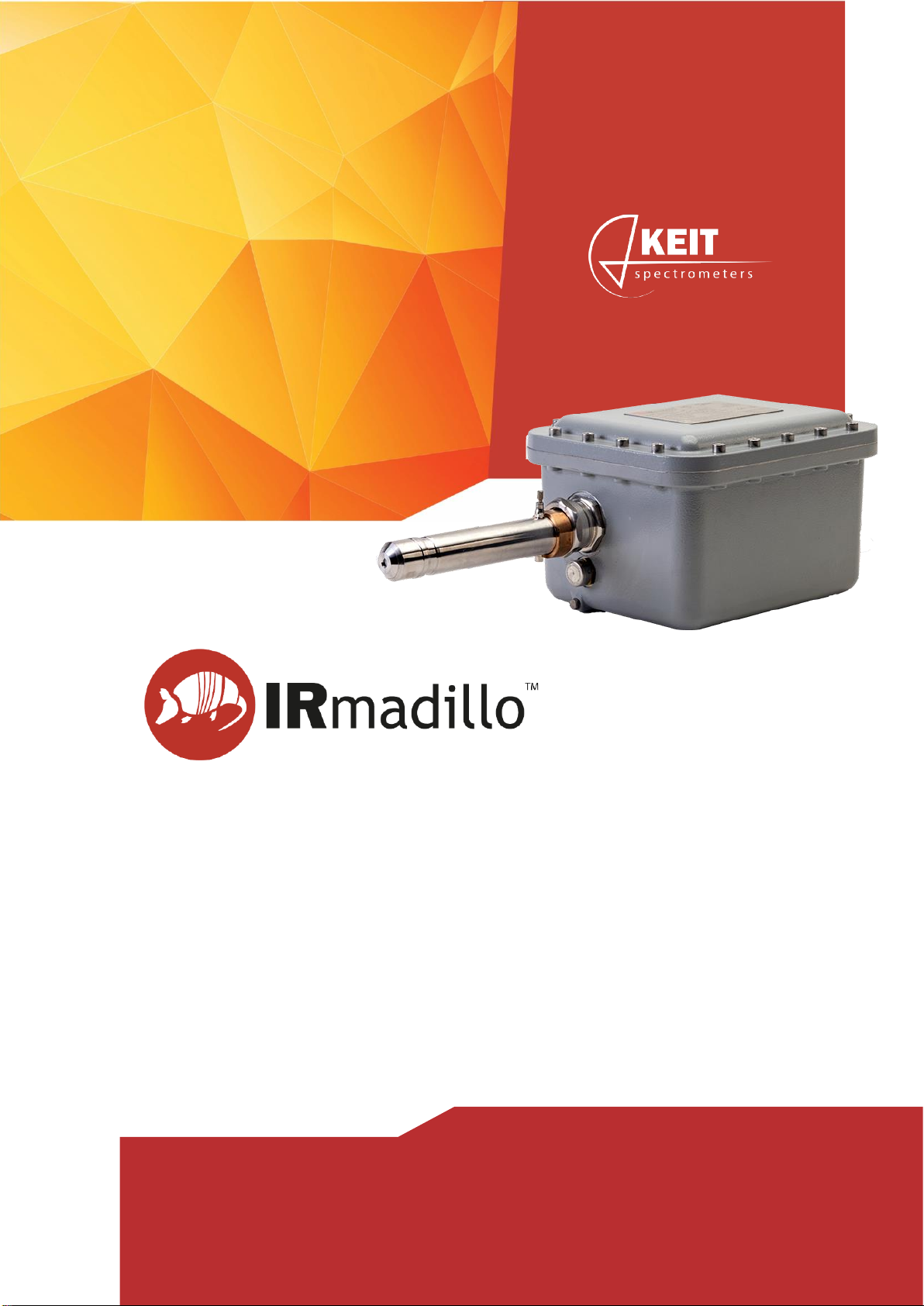
2.1. Starting the unit
1. Close the outlet flow control valve (10).
2. Connect the unit toa single-phase power supply (7) andto your compressed air supply
(1).
3. Check that air is not venting through the drain valve (8). If the initial pressure is too low
or if the pressure is increased too slowly, the spring valve on the mist separator will
not close, so air will be vented through the drain valve. If this is the case, block the
drain for a few seconds; this should allow the spring valve to close.
4. Turn the unit on using the front panel switch (3).
5. Ensure that the inlet pressure gauge (4) reads between 6 and 10 bar.
6. Leave the unit runningfor a minimum of three hours. This will ensure that the desiccant
has regenerated, and the air outlet is dry.
7. Open the outlet flow control valve (10). Do not connect your spectrometer to the outlet
valve at this point.
8. Set the outlet flow rate such that each spectrometer connected to the unit will receive
0.5 litres/min - 2 litres/minute, do this by opening the flow regulator (21). Take note of
the flow rate set.
9. Connect your spectrometer(s) to the outlet (10) using Ø4 mm tube.
10. Confirm that the outlet flow rate is consistent with the flow rate set in step 8. If not,
adjust the outlet flow control valve (21).
11. Close and lock the panel doors (6).
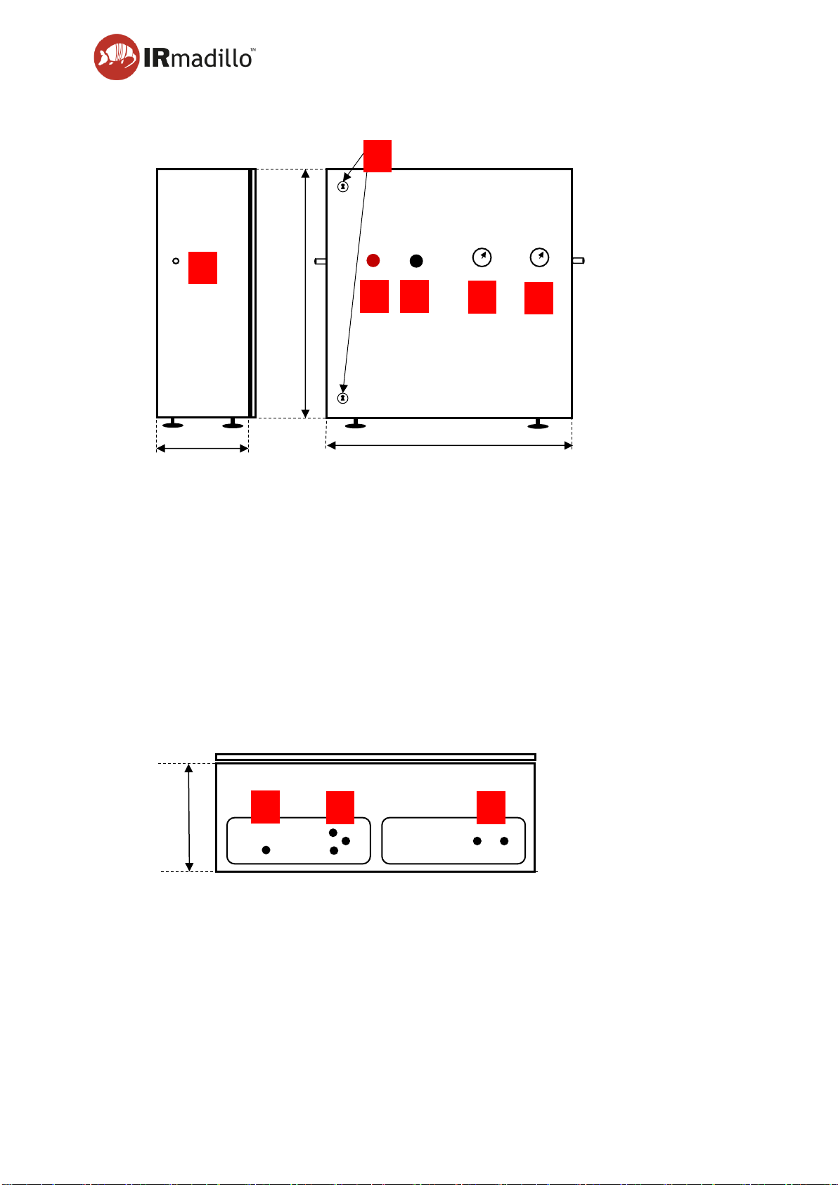
2.2. During regular use
The reservoirs on the mist separator (12) and 5m filter (14) will gradually fill up as water is
condensed out of the air. Periodically, check that the glass bulbs are not full. If the bulbs do
fill up, turn the unit off using the front panel switch(3) and disconnect or isolate your air supply
momentarily. This will open the spring valves on the mist separator and filter and allow the
water to drain through the drain valves (8).
The frequency with which the reservoirs need to be emptied will depend on the humidity of
your input air.
2.3. Stopping the unit
1. Turn off the unit using the front panel switch (3).
2. The compressed air in the unit will vent via the muffler valves on the base of the unit
(9).
2.4. Long-term storage
The unit may be stored for up to six months at a temperature of 0-30°C in a non-condensing
atmosphere. Keit recommends storing the unit in an indoor location. Maintenance should be
carried out as per the schedule (see section 3.1).